Note : Les descriptions sont présentées dans la langue officielle dans laquelle elles ont été soumises.
CA 02242042 1998-07-02
WO 98120628 PCT~S97/19885
APERTURE-TO-RECEIVER GAIN EQUALIZATION
IN MULTI-BEAM RECEIVING SYSTEMS
This invention relates to bearn channel gain equalization in multi-bearn
antenna systems and, more particularly, to methods for aperture-to-receiver gain5 equ~li7~tion between beam çhqnnPl~ in cellular radio systems to enhance bea n
channel selection based on received signal strength.
BACKGROUND OF THE INVENTION
Usage and inct~llation of cellular radio systems are rapidly e~p~n-iing. As a
result, system capabilities and ç~pacities for both volume of concurrent user messages
10 and system coverage area are increasingly important for operative and economic
reasons. Increased volume or increased coverage area, or both, can enable required
user capacity to be provided with fewer system in~t~ tions
Multi-beam antenna systems provide capabilities addressing these objectives.
For example, using available antenna technology, coverage for a 90 degree cell sector
15 can be provided by an antenna configuration fed by a beam forming network. Four
side-by-side antenna beams each about 22.5 degrees in azimuth width at their half-
power points can cover the 90 degree sector. With such an arrangement of four
beams, the r~ cçnt beams will cross over or overlap each other at their half-power
points. As a result~ a user signal incident to the antenna svstem at an angle at or in
20 the vicinity of a beam crossover angle will be received via both adjacent antenna
beams.
By use of such a multi-beam al,~nge,l,c,.~, increased coverage results from
greater usable range provided by the narrower, higher gain antenna beams, as
coll,pared to a single 90 degree beam pattern. For most effective operation,
2~ cornrnunication with a mobile user in the sector requires selection of the beam
enabling reception of the strongest signal, e.g., reception of a user signal with the
highest relative signal level. For a user signal incident at an angle near the center line
of a particular beam, beam selection for highest signal strength is relatively easv.
However, if a particular user signal-is incident to the antenna svstem at an azimuth
30 an~le at or close to a beam crossover angle. the user signal will appear in the beam
channel of each of the two adjacent beams with comparable si_nal strength. The
CA 02242042 1998-07-02
W 09~20628 PCTAUS97/19885
term "beam channel" is used to refer to the signal trancrnission path (e.g., cables~
amplifiers, switches, etc.) from the antenna aperture to a receiver lac~ed.s~rnedistance from the antenna as effective for coupling signals received via a specific
amenna bearn
Even in the case of co-l-?a-dble signal strength in two adjacent beam channels,
the beam channel providing the sl- onges~ signal can be selected for reception of the
user's signal. If signal amplitude in two çh~nnelc is equal an arbitrary choice can be
made. A problem can arise, however, if the received user signal is coupled from
amenna to receiver via two beam ch~nnelc having di~en~ aperture to receiver gains.
10 Simply put, a beam channel receiving a weaker user signal, but having higher overall
beam channel gain, may be selected over a second beam channel which is actually
receiving a stronger user signal, if the second channel has a lower overall beamchannel gain. If that result occurs, system performance will typically be de_raded
because the highest quality received signal has not been selected. At the limit,15 selection of the weaker version of the user signal may foreclose acceptable
intelligibility, while selection of the stronger version ~as received at the aperture)
might have enabled acceptable communication of the information content of the user
signal.
It has been found that in the worst case, for an incident angle near or at a
20 beam crossover angle, a chaMel gain differential can degrade performance on a dB
for dB basis. Thus, if beam A receives a user signal at a level 3 dB below the si_nal
strength at which the same user signal is received in beam B, but beam channel A has
a 3 dB higher gain from aperture to receiver, selection of channel A can cause the
system to operate with 3 dB poorer signal quality for the user signal. A typical25 antenna system may include beam çh~nn~lc from aperture to receiver having as much
as 40 dB nominal gain to ovclcol.,e 30 dB nominal loss. Channel gain may be
provided by preamplifier units, for example. Channel loss is typically caused byinclusion of successive lengths of intel co~ e~ui-g cable, as well as switches and other
electronic components and coupling devices. With such configurations, initial beam
30 channel gain may differ signific~ntly from channel to channel and. after inst~ tion,
component aging and drift may also result in further differences in relative channel
gains. Thus, for a variety of reasons ~there can be significant difference between gains
in adjacent beam ch~nn~lc and such .li~-ences in gain can mask differences in
-2 -
CA 02242042 1998-07-02
W O 98~0628 PCT~US9711988
received signal levels and affect system performance.
Objectives of the present invention are to provide new and i}nproved methods
for aperture-to-receiver gain equ~li7~tion for beam channels of a multi-beam
receiving system, particularly such a system employing beam channel selection based
5 on received signal strength. Methods in accordance with the invention typically
provide one or more of the following characteristics and capabilities:
- automated gain eq~li7~tion for a plurality of bearn ch~nnels;
- enhanced multi-beam system pc~ro~ ance through improved bearn selection
for ~l~onges~ received signal;
- beneficial utilization of low level noise signals (e.g., receiver front end noise
signals) inherenlly available between information signals;
- multi-channel relative gain calibration without use of a reference signal
generator;
- oplimized multi-beam cellular system operation by improved beam selection;
1 5 and
- economical derivation of gain correction factors for equalization of aperture-
to-receiver gains of parallel beam channels.
SUMMARY OF THE INVENTION
In accordance with the invention, a method of aperture-to-receiver gain
equalization, for use in a multi-beam receiving system employing beam channel
selection, eq~qli7~tion inc~udes the steps of:
(a) providing a plurality of antenna to receiver beam ch~nnçlc each
coupling a signal representative of a signal received via one of a plurality of partially
overlapping antenna beams;
(b) determining for a first beam channel a threshold level represçnting the
lowest signal level measure during an initial period;
(c) after the initial period, monitoring signal level in the first beam channel
during a monitoring period to determine a subsequent lowest signal level;
(d) col-lpa,i-lg such subsequent lowest signal level to the threshold level
to derive a first gain correction factor for the first beam channel;
(e) I epeal;l-g steps (b) through (d) for a second beam channel of the
plurality of beam ch~nnel~, to derive a second gain correction factor for the second
beam channel;
-3 -
CA 02242042 1998-07-02
W O 98/20628 PCTAUS97/19885
(f) utilizing the first and second gain correction factors to provide
respective ~djusted signal levels for info.-ndlion signals rëceived,in-;such ~ nnels~ an~.
(g) selecting for reception of the information signal the one of the first
and second beam ch~nn~l~ providing the highest ~djll~ted inforrnation signal level.
In application of the invention, it may typically be arranged that the thresholdlevel in step (b) ,~"eseills the lowest in~ neo~ls signal level measured during an
initial period which exceeds one hour in duration, with such signal level re~.~se~,l;ng
an inherent noise level (i.e., thermal noise) measured during periods between
reception of successive info- ~I-alion signals. The same approach can be followed in
determining a subsequent lowest signal level in step (c). Also, in order to improve
stability of operation, it has been found desirable to gradually increase the threshold
level to a higher level during the step (c) monitoring period, while determining a
subsequent lowest signal level, as will be further ~iccucced
For a better underst~n-ling of the invention, together with other and further
objects, reference is made to the accompanying drawings and the scope of the
invention will be pointed out in the accompanying claims.
BRIEF D~SCRIPTION OF THE DRAWINGS
Fig. 1 is a simplified block diagram of a multi-beam receiving system
including a parallel configuration of selectable aperture-to-receiver beam channels.
Fig. 2 is a flow chart useful in dese- il,ing a method of aperture-to-receiver
gain equalization in accordance with the invention.
Fig. 3 is a flow chart useful in describing a method of positive decay
~cijustm~nt of lowest noise threshold value in application of a gain equalization
method in accordance with the invention.
DETAILED DESCRIPTION OF THE ~NVENTION
Fig. 1 is a simplified block diagram of a multi-beam receiving system 10
suitable for receiving cellular radio signals from users located within a 120 degree
sector relative to an antenna inct~ tion While the 120 degree sector could, for
example, be covered by an antenna having a radiation pattern providing a single beam
~,vith a 120 degree beam width, higher gain coverage can be provided by use of four
beams 12, 13, l 4, 15, each nominally 30 degrees wide at half power points, as
-4 -
CA 02242042 1998-07-02
W O 98/20628 PCT~US97119885 --
illustrated. Thus by use of a suitable beam forming network 16 coupled to a suitable
form of antenna 18 comprising an array or other confi~lJr~tion of r~iating elements~ ~
received signals l~plesentative of the beams 12, 13, 14 15 can, in known manner, be
made available in beam channels 22, 23, 24, 25, respectively.
With this arrangement, signals received at aperture 26 of antenna 18 are
coupled from the antPnn~, which may be remotely positioned on the top of a tower or
building, to a receiver in~t~ tion for processing of signals and distribution tointended information signal recipients, via wire or other communication facility. On a
simplified basis, an incoming signal is received via one of beams 12- 15 and provided
at output port 30 for suitable trancJnission to the intended recipient. Receiverprocessor 32 is arranged to control switch 34 for this purpose, and may be responsive
to comparison of signal strength in ch~nn-olc 22-25 prior to switch 34 (or after switch
34, if the switch initially is operated on a samplin~ basis). In a currently preferred
embodiment, sampling is accomplished via points 22a, 23a, 24a and 25a prior to
switch 34, in which case the connection of receiver processor 32 to point 33 may be
ornitted.
In the most straightforward case, a user transmitting a cellular signal may be
positioned at an ~7imllth location relative to antenna 18, such that the user signal is
received primarily along centerline 12a of beam 12. In this simple case beam 12 and
beam channel 22, providing signals represenlative of beam 12, will provide the
strongest signal level for the received signal. However, if the user is positioned so
that the user signal is incident to the antenna 18 at an angle corresponding to one of
lines 12/13, 13/14 or 14/15, the signal will be received in two adjacent beams with
e~ual signal strength. This will also be true for incident angles relatively close to the
azimuths represented by lines 12/13, 13114 and 14/15, although the signal levels in
the two beams will differ, depending on the gain provided by the radiation pattern
effective for a particular angle.
As diccllssed above, best system perforrnance will be achieved by selecting
the beam channel cont~ining the strongest signal, or highest signal level, for an
incorning received signal. However, such signal selection must typically be made at a
receiver inctall~tion remote from the antçnn~, so that differences in aperture-to-
receiver gain may override or obscure actual signal level differences in a received
signal which has been coupled via di~l.,.-l beam channels. It will be appreciated that
CA 02242042 1998-07-02
W 0 98no628
PCTAUS97/19885
in a particular inct~nrç, att~inm~nt of such best system performance may be obviated
by some overriding factor (e.g., channel noise, component failure, etc.) however such
effects are beyond the scope of present considerations.
As shown in Fig. 1, output port 30, from which received signals are made
5 available for further processing and trancmission to an intended recipient, is remote
from ~nt~nn~ 18. Each of beam ch~nn~lc 22-25 may typically include succescive
lengths of interconnectin~ coaxial or other cable as well as switches and other
electronic components and coupling devices. In Fig. I the various cltclrol iG
components and connectors which may be included in a beam channel are I eprese.,led
10 collectively by switch 34, the intercoupling line sections, as shown, and units 36
generally representing other tran~miscion path components. In total, such line
sections and components may lel).eselll a level of signal loss or degradation of the
order of 30 dB, for example. To offset such loss in order to provide usable signal
levels, preamplifier and other amplifier devices providing on the order of 40 dB gain
15 may also be included in each of beam channels 22-25. For present purposes, the
amplifier device or devices included in each beam channel are collectively lepresei-led
by units 38.
During assembly of system 10 in accordance with the invention it will
norrnally be desirable to select the various components for inclusion in each of beam
20 channels 22-25 with the objective of providing closely similar, if not equal, aperture-
to-receiver gains for each beam channel. However, small incremental differences in
signal level can be significant in providing optimal system perforrnance and there is a
practical and economical limit to the level of effort which can be expended in
component selection for overall beam chaMel gain equalization. As a practical
25 matter, an approach to provide an acceptable level of ~ain eq~ 7~tion may be based
on a m~mlf~cturing standard requiring the gain or loss provided by each specific unit,
module and cable to be held within a tolerance of ~ 0. 5 dB, for example, of a
specified nominal value. Such a standard addresses beam channel gain equalization,
while also pe~ ing components to be employed on an interchangeable basis for
30 initial assembly as well as field replacement. It will be appreciated, however, that if a
channel-to-channel gain tolerance of ~ 0.5 dB or + 1.0 dB is desirable on an overall
basis, even close individual coll.pon~,n~ tolerances can not be relied upon to meet
such overall tolerance between complete channels. In addition, even if channel gain
-6-
CA 02242042 1998-07-02
W O 98i20628 PCTrUS97119885 -
could be closely equalized initially, component aging, field repl~c.~ments, etc. could
alter such gain equ~li7~tion.
Pursuant to the invention, beam channel selection for best received signal
strength in a system such as shown in Fig. I, utilizes continuing derivation of gain
5 correction factors. Such gain correction factors, lep~ese,llative of relative difference
in aperture-to-receiver gain between beam çh~nnçlc, are applied to calibrate the level
of an i.~.-,.dlion signal received via dif~.e.ll bearn çh~nnelc With such calibration,
in the nature of signal inte,yre~alion~ co"-pel s&lion or adju~ment, the beam chaMel
actually providing a signal reple3e.ltali~/e of the strongest version of the incoming
10 information signal can be selected.
In Fig. 1, receiver processor 32 includes a single common receiver arranged
to obtain signal level measurements for each of ch~nn~l~ 22-25 on a repetitive
scanned basis. As illustrated, receiver processor 32 is coupled to respective signal
sdlll~)ling points 22a, 23a, 24a and 25a of ch~nnelc 22-25, via sr~nnin~ switch 40.
5 Switch 40 is effective to sequentially couple samples of signals from particular ones
of channels 22-25 to receiver processor 32, under receiver processor control or on a
pre-programmed sequential basis. Gain correction factors reflecting channel-to-
channel di~erellces in threshold levels representing lowest signal levels measured in
the ch~nn~lc are developed by receiver processor 32. Then, when a user signal is20 received via two of the ch~nnl?lc the gain correction factors are utilized to compare
the signal levels to enable selection of the channel receiving the highest signal level.
Under the control of receiver processor 32, switch 34 is activated to couple theselected channet to output port 30 to enable further processing and use of a received
information signal by an intended recipient. By use of a single common receiver to
25 receive signal samples from all of the channelc~ distortion of results due to variations
in receiver pa~ ers are avoided (i.e., a "common yardstick" is used for relative
measurel,lt;llls) .
A key feature of methods in accordance with the invention is the constructive
use of noise signals (e.g., front end noise) appea~h~g in a beam channel when no30 information signal is present. Thus, the noise signal utilized typically represents a
combination of thermal noise (e.g., antenna looking at 300 degree Kelvin ambienttemperature of the atmosphere), plus a small contribution from a prearnplifier,
amounting to about a 1.2 to 1.5 dB noise figure. Pursuant to the invention,
-7-
CA 02242042 1998-07-02
wO 98/20628 PCT/US97/I988~ -
monitoring of the lowest signal level apl~ea""g in a bearn channel over an extended
period of time is utilized to represent the monitoring of how a standard signal is
affected by the aperture-to-receiver gain of a beam channel. Accordingly~ if twobeam çh~nnçlc actually had identic~l aperture-to-receiver gains, the measured
5 ~mrlitude of the lowest signal level at the beam channel outputs (typical}y
ese~ni~ front end noise) would also be identic~l Since the lowest noise signal
thus provides a standard signal level in each çh~nn~l, cham el to-channel differences
in aperture-to-receiver gain can be deterrnined as gain correction factors. Then,
when an il~o.",alion signal of unknown relative signal level is received in each oftwo
I 0 beam ch~nnelc, the gain correction factors can be used to select the channel actually
providing the strongest received signal level.
A measurement of the lowest signal level in a beam channel cannot reliably be
made at any p~eselt~led instant in time. An incoming h~....aLion signal, an
interference signal, a burst of noise, or some other effect may increase the signal level
at any selected instant in time. In view of this, the invention utilizes an extended
listening period, possibly of an hour or several hours, in order to determine the
lowest instantaneous signal level measured at any time within such extended period.
For a given system, a dete.l...nation can be made on the basis of repeatability,channel-to-channel consistency, etc., as to choice of an appropriate listening period
duration.
Typically, once a lowest signal level is determined for a given beam channel, itis considered as a threshold value for that channel. Then, lowest inst~nt~neous signal
level monitoring is continued during system operating periods and if a lower signal
level is experienced, it is used as the new basis for the threshold value. As will be
further described, on an extended time basis a teçhnique such as slowly increasing the
threshold value (subject to occurrence and recognition of lower lowest signal levels)
may be employed. Such technique enables system recognition of a channel gain
which degrades for some reason and can also be arranged to avoid unstable opc. ~ling
conditions, such as open looping upon a slow gain change in a particular direction.
For similar reasons of overall system accuracy and stability, it may also be desirable
to program operation for re-initi~1i7~tion to periodically carry out a new threshold
selection independently of the value of a threshold previously utilized for a given
c.h~nn~i
-8-
CA 02242042 1998-07-02
W O 981~0628 PCTrUS97/19885 -
A method of aperture-to-receiver gain equ~li7~tion in accordance with the
invention can be more particularly considered with reference to the flow chart of
Fig.2. The invention provides methods of aperture-to-receiver gain equalization
particularly applicable to use for beam channel selection to provide improved signal
S reception in a multi-beam receiving system.
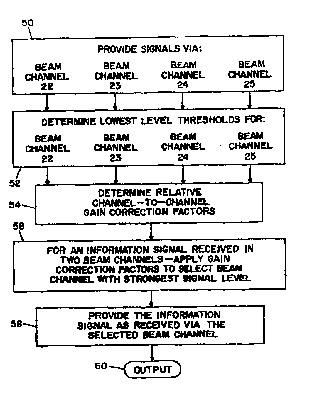
At step 50 of Fig. 2, signals are provided via beam ch~nnels 22, 23, 24, 25.
With reference to Fig. 1, this may be accomplished by providing a plurality of beam
çh~llnel~ 22-25. Each beam channel is arranged to couple a signal received via one of
a plurality of respective antenna beams 12-15 which, as dicc~lssed with reference to
Fig. 1, are arranged in partially overlapping beam patterl relationship to provide
coverage of a selected cell sector. It will be apprecidted that, under normal operating
conditions, at difrerent instants of time the signals provided via the individual beam
channels may comprise:
(i) information signals received via one or more beams, depending on the
imllth position of a mobile user,
(ii) local or other noise, spurious or interference signals received via one
or more beams at diLrel elll or the same signal levels; or
(iii) low level background or "front end" noise which can be expected to be
present cimult~neously in all beam ch~nnelc at identical or nearly identical
levels.
In Fig. 2, at step 52 there is determined for each beam channel 22-25 a
threshold level 1 e~" esenlative of the lowest signal level measured in a time period
(e.g., the lowest inct~nt~neous signal level measured at receiver processor 32 of Fig.
I over a one hour period). It will be appreciated that even though there may be
incorning information signals being processed, there will be quiet instants between
such signals. By monitoring signal level over a long enough period of time (e.g., for
a fraction or multiple of an hour, depending partially on the particular embodiment)
there can be a high degree of certainty that the lowest inst~n~neous signal level
measured represents a background type of noise level which will commonly and
equally affect each beam channel.
At step 54, channel-to-channel differences in the threshold level for each of
ch~nn~.lc 22-25 are utilized to derive gain correction factors. Such gain correction
factors will be repl esen~atb~e of relative difference in aperture-to-receiver gain
CA 02242042 1998-07-02
wo ss/io62s
PCT/US97119885
between the beam ch~nn~lc The gain correction factors may be provided in any
suitable form and may, for e~nl~le, each include a suitable base con~lanl or pedestal
value, so that the smallest factor is fepre~e"led by such pedestal value and others are
respectively larger, to reflect channel-to-channel gain differences.
At step 56, the gain correction factors are applied for channel selection
purposes. Based on the previous discussion, it will be recalled that if an incoming
user signal appears in two beam cl-Anncls operating pe- rOl ~l~ance is çnhqnced (or
pe.ro.l..ance degradation is avoided) by use ofthe signal from the beam channel
receiving the strongest version ofthe inroI-l-alion signal. Merely cGI~)alillg signal
levels of the same signal at the outputs of two beam channels may be misleading,because a stronger signal in one channel may be overshadowed by a higher gain in the
other channel (making its version of the signal appear stronger). With the availability
of the gain correction factor, it will be apparel.~ to skilled persons that such factors
can be applied in a variety of ways in order to compare the signal level of a user
signal incorning via two adjacent beam ch~nnçl~. Thus depending upon the particular
implem~nt~tion, the gain correction factors may be applied via a circuit arranged: to
interpret relative signal levels in view of the relevant factor or factors, to compensate
one signal level for comparison with the other signal level; to adjust the signal levels
to enable direct comparison; etc. A microprocessor or other suitable arrangementmay thus be provided to rapidly apply a gain correction factor to one or both ~ cçnt
~h~nnels, in order to offset the inherent relative gain difference in aperture-to-receiver
gain. By reducing the effect of the relative gain difference between the c.h~nnel~
beam channel selection for reception and processing of the stronger version of the
received signal is enabled.
With selection of the beam channel providing the higher level of the incorning
user signal, at step 58 in Fig. 2 information signals as received from that user are
provided for further processing and at 60 can be provided as an output for
comrnunication to the user's intçncled lecii)ient.
It will be appreciated, with ~ ~rerence to Fig. 1, that a particular user signalmay have been incoming via beams 12 and 13 and beam channels 22 and 23. A
second user signal may then be received via beams ] 4 and 15 and beam channels 23
and 247 for example. The same method of channel selection is repeated to select
beam channel 23 or 24 as providing the strongest version of the second user signal.
-10-
CA 02242042 1998-07-02
W 098/io628 PCT~US97/19885
Such additional channel selections may be implçmented in series or additional system
capabilities may be added to the Fig. I arr~n~çment to enable more than one channel
selection process to be implP~mpnted at the same time, in parallel operations. Also,
the first user may be in a moving vehicle so that whereas the strongest signal for this
user was initially received via beam 12, the strongest signal for this user may later be
received via beam 13 . With an und~ g of the invention, skilled persons will be
enabled to provide repetitive channel selection proceccing~ and other variations and
co.,.l,inzlions of processing steps, as suitable to a variety of system implementations,
Opt~l aling volume of incoming calls and other parameters. In this context, it will be
appreciated that the invention may be applied to antenna systems providing two or
more beams, and is not limited to a four beam system as described by way of
example.
Pursuant to the foregoing, in order to enable selection of one beam channel
for reception of an inforrnation signal incorning via two beam channels, a method of
aperture-to-receiver gain equalization may include the steps of:
(a) providing a plurality of antenna-to-receiver beam channels each
coupling a signal representative of a signal received via one of a plurality of partially
overlapping antenna beams;
(b) dete- lll.ning for a first beam channel a threshold level representing the
lowest signal level measured during an initial time period,
(c) after the initial period, monitoring signal level in the first beam channel
during a monitoring period to determine a subsequent lowest signal level;
(d) comparing the subsequPnt lowest signal level to the threshold level to
derive a gain correction factor for the first beam channel; and
2~ (e) utilizing the gain correction factor as a signal strength adjustment for
the first channel during beam channel selection for reception of an i.~l.l.a~ion signal.
Referring now to Fig. 3, there is illustrated a flow chart for a threshold levelm~n~g~ment method, in accordance with the invention. F.csP.nti~lly, as describedabove, the current lowest signal level, measured on an in~t~nt~neous basis for aparticular beam channel is the threshold level for that channel. However, in particular
applications it will be necesS~ry to avoid the possibility of an "open looping" effect
whereby a threshold level is set at a specific level, but the aperture-to-receiver gain
for that channel thereafter decreases to a lower level (e.g., due to a relatively small
-1 1-
CA 02242042 1998-07-02
wO 98/20628 PcT/uss7/198ss
degradation in component or amplifier characteristics). As a result, the threshold
level should be set higher for that beam channel relative to the other beam channels,
but the lower existing threshold would preclude recognition of a new higher
threshold level. In accordance with a currently preferred embodiment, this result of
potentially retaining an el,uneously low threshold value for a particular chaMel is
avoided by a pro~ "ed increase in the threshold level. Thus, by introducing an
artificial very gradual increase in the threshold level, the opportunity for accurate
reset of the threshold level is enh~nce~l As the threshold is gradually increased to
higher and higher levels (by a ramping constant applied for all ch~nnelc) a point will
be reached at which a measured lowest noise level will cause the threshold level to be
reset to a new threshold level based on an actual present measurement of the lowest
h~sL~~ eous noise signal.
With reference to Fig. 3, at step 70 a current lowest noise measurement is
provided for a beam channel (e.g., channel 22 of Fig. 1). At step 72 that current
lowest noise level is compared to the previously selected threshold level for that
channel. The previous threshold level may represent a previously measured lowestnoise level for channel 22, for example, or, in a start-up mode~ a predeterminedthreshold level assigned as an initial or default value.
If the current noise level is lower than the previous threshold level, at step 74
the current lowest noise level is substituted as the new threshold level. At step 76, a
positive decay adjustment is determined. For example, such decay adjustment may be
represenled as a parameter "a" having a value equal to I over 2n, which for a value of
n=21 can be arranged to provide a gradual voltage rise from zero to 0.5 volts over a
period of about 4.4 hours. In a particular application, the decay adjustment could be
initi~ted with a starting value of 0.25 volts and be arranged to increase from 0.25
volts to 0.75 volts over a period such as 4.4 hours. A very gradual increase useful as
a positive decay adjustment is thus provided as a control against open looping effects.
In Fig. 3, at step 78 an adjusted threshold level is deterrnined as the total of(a) the lower of the new threshold level from step 74 or the threshold level as
previously existing, plus (b) the current value of the positive decay adjustment from
step 76.
At step 80, steps 70, 72, 74, 76 and 78 are repeated for the next beam
channel (e.g., repetitiously for beam ch~nnel~ 23, 24, 25, 22, 23, 24, 25, 22~ etc.). It
-l2-
CA 02242042 1998-07-02
W 098/20628 PCTAUS97/19885
will be appreciated that if the positive decay adjllstm~nt (growing at a slow rate over
a period of hours) is applied in relatively close succescion in determining adjusted
threshold levels for each beam çhAnn~l the decay adjustm~nt will effectively increase
or distort the actual lowest noise levels of each channel by subst~nti~lly the same
S amount. At step 82, gain correction factors are determined for each channel, based
on channel-to-channel di~nces between the current adjusted threshold levels fromstep 78 for the various beam çh~nnel~. With the positive decay ~dj~lstment affecting
each beam channel by substantially the same amount, as discussed, the results of step
82 will effectively be independent of the value of the decay adjustment.
At step 84, the respective correction factor from step 82 is added to incoming
signals in each of the beam çh~nnPlc to equalize signal levels for signal processing.
Thus, assume that one the basis of comparison of the adjusted threshold levels it is
determined at step 82 that the aperture-to-receiver gain of channel 22 is 2 dB higher
than that of channel 23 . Accordingly, at step 84 in this example a correction factor
would be added to the signals in channel 23 relative to the signals in channel 22.
With the aperture-to-receiver gains of the two c.h~nn~lc thus equalized, the signal
levels of a specific incoming user signal appearing in both channels can be directly
compared in order to select the channel providing the strongest user signal for further
processing and ~1 ~nc,..ll l~l to the intended recipient. With an underst~n(ling of this
example, persons skilled in cellular communications will be enabled to employ lowest
level noise measurements in various chaMel selection applications, in accordancewith the invention.
While there have been described the currently preferred embodiments of the
invention, those skilled in the art will recognize that other and further modifications
2~ may be made without departing from the invention and it is intended to claim all
modifications and variations as fall within the scope of the invention.