Note : Les descriptions sont présentées dans la langue officielle dans laquelle elles ont été soumises.
- CA 02242806 1998-08-27
PATENT
97-AE4-401/TSC
DISPT~Y SYSTEM
P~ckgrol~n~ of ~h~ Tnvent; ~n
The present invention relates to a display system
which is capable of being illuminated with different
colors.
Display systems are commonly utilized in association
with push-button actuated switches, annunciators, and
signaling devices. A known display system is disclosed in
U.S. Patent No. 5,295,050. This known display system is
constructed so as to be readable in bright sunlight. The
display system includes a prism having a pair of light
receiving faces.
When a light source is energized in the display system
of U.S. Patent 5,295,050, light is transmitted to the light
receiving faces of the prism. Light is transmitted through
the prism to a light emitting face of the prism. A display
panel is disposed in front of the prism.
Summary of the Invent;on
The present invention provides a new and improved
display system having a display panel connected with a
CA 02242806 1998-08-27
--2--
housing. A plurality of light sources are disposed in the
housing. A plurality of color filters are disposed between
the light sources and the display panel.
A first light source of a plurality of light sources
is energizeable to transmit light through a first color
filter of the plurality of color filters to illuminate the
display panel with a first color, for example, red. A
second light source of the plurality of light sources is
energizeable to transmit light through a second color
filter of the plurality of color filters to illuminate the
display panel with a second color, for example, green. The
first and second light sources are both energizeable to
illuminate the display panel with a third color, for
example, yellow.
The display panel includes inner and outer layers
containing light absorbing pigment and light scattering
particulates. The outer layer of the display panel
contains'a relatively large amount of pigment in addition
to light scattering particulates. The inner layer of the
display panel includes a relatively large amount of light
scattering particulates and a smaller amount of light
absorbing pigment.
Brief Descri~t;on of the Draw; n~s
The foregoing and other features of the invention will
become more apparent upon a consideration of the following
description taken in connection with the accompanying
drawings wherein:
CA 02242806 l998-08-27
-3--
Fig. 1 is a pictorial illustration of a display system
constructed in accordance with the present invention;
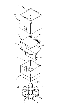
Fig. 2 is an exploded pictorial illustration depicting
components of the display system of Fig. 1;
Fig. 3 iS a schematic sectional view, taken generally
along the line 3-3 of Fig. 1, further illustrating the
construction of the display system; and
Fig. 4 iS a fragmentary sectional view of a portion of
a display panel used in the display system of Figs. 1-3.
Description of One Specific
Preferred ~m~o~;m~nt of the Tnvent-;on
GenerA1 Description
A display system 10 (Figs. 1, 2 and 3) constructed in
accordance with the present invention includes a
rectangular housing 12 which includes a base section 14 and
a shroud section 16. A rectangular display panel 20 iS
connected with an upper (as viewed in Figs. 1-3) end
portion of the shroud section 16. A plurality of light
sources 24 and 26 (Figs. 2 and 3) are disposed within the
housing 12 on the base section 14.
In the illustrated embodiment of the invention, each
of the light sources 24 and 26 (Figs. 2 and 3) includes a
pair of lamps, that is, devices for producing light. Thus,
the light source 24 includes lamps 30 and 32. The light
source 26 includes lamps 34 and 36. The lamps 30-36 are
disposed in a rectangular array on the base section 14.
The lamps 30-36 may be solid state devices, such as light
emitting diodes, or may be incandescent sources of
CA 02242806 1998-08-27
--4--
illumination. Although each of the light sources 24 and 26
includes a pair of lamps, it is contemplated that each of
the light sources could contain either a greater or lesser
number of lamps if desired.
In accordance with a feature of the present invention,
color filters 42 and 44 are disposed between the light
sources 24 and 26 and the display panel 20. The color
filters 42 and 44 are homogeneous optical mediums that
absorb certain regions of the visible spectrum. Thus, the
color filters 42 and 44 are used to isolate different
regions of the visible spectrum and to pass light of a
chosen region quite freely while absorbing all other
visible light. In the illustrated embodiment of the
invention, the color filter 42 iS red color filter which
transmits visible light having a wavelength corresponding
to the color red. The color filter 44 iS a green color
filter which transmits light of a wavelength corresponding
to the color green. Of course, different color filters
could be utilized if desired.
When the light source 24 iS energized, that is, when
the lamps 30 and 32 are illuminated, red light is
transmitted through the color filter 42 to the display
panel 20. This results in the display panel being
illuminated in red light. When the light source 26 iS
energized, that is, when the lamps 34 and 36 are
illuminated, green light is transmitted through the color
filter 44 to the display panel 20. This results in the
display panel being illuminated in green light.
CA 02242806 1998-08-27
--5--
If both light sources 24 and 26 are simultaneously
energized, light is transmitted through both color filters
42 and 44. This results in light of primary red and green
colors being mixed to illuminate the display panel 20 in
yellow light. It is contemplated that colors other than
red, green and yellow could be utilized to illuminate the
display panel 20 if desired.
It should be understood that the amount of color
saturation and purity of the yellow light is dependent upon
the spectral transmission characteristics of the red light
transmitted by the color filter 42 and the green light
transmitted by the color filter 44. The production of the
yellow light in this manner requires pairing the spectral
transmission properties of the red color filter 42 and the
green color filter 44 so as to lessen the propensity of
color dominance in the final output color (yellow) and to
enhance color purity.
When the display panel 20 is to be illuminated in
yellow light, it is preferred to energize only one of the
lamps 30 or 32 beneath the red color filter 42 and only one
of the lamps 34 or 36 beneath the green color filter 44.
By energizing only one of the lamps in each of the light
sources 24 and 26, the brilliance of the yellow light in
which the display panel 20 is illuminated is the same as
the brilliance of the red or green light in which the
display panel is illuminated when both of the lamps in one
of the light sources 24 or 26 are energized. When the
display panel 20 is to be illuminated in yellow light,
CA 02242806 l998-08-27
--6--
uniformity of illumination is promoted by energizing
diagonally opposite lamps 30 and 34 or 32 and 36 (Fig. 2)
in the rectangular array of lamps.
The base section 14 of the housing 12 includes an
opaque divider panel 50 (Figs. 2 and 3) which is disposed
between the two light sources 24 and 26. Therefore, when
the light source 24 iS energized and the light source 26 iS
de-energized, light is transmitted through only the red
color filter 42 to the display panel 20. At this time,
there is no light transmitted through the green color
filter 44 to the display panel 20.
Similarly, when the light source 26 iS energized and
the light source 24 iS de-energized, light is transmitted
through the green color filter 44 to the display panel 20.
At this time, there is no light transmitted through the red
color filter 42 to the display panel 20. Of course, when
both light sources 24 and 26 are illuminated, a mixture of
red and green light, that is, yellow light, is transmitted
from the color filters 42 and 44 to the display panel 20.
In accordance with another feature of the present
invention, the display panel 20 includes an outer layer 54
and an inner layer 56 (Figs. 3 and 4). The outer and inner
layers 54 and 56 of the display panel 20 each contain light
absorbing pigment and light scattering particulate. The
outer layer 54 contains a greater quantity of light
absorbing pigment than the inner layer 56. The inner layer
56 contains a greater quantity of light scattering
particulate than the outer layer 54.
CA 02242806 1998-08-27
-7--
The relatively large quantity of light absorbing
pigment in the outer layer 54 promotes attenuation of
direct sunlight to maintain obscurity of the display panel
10 when high ambient incident light is directed at
relatively small angles relative to the normal of the
display panel. This virtually eliminates any of the
reflected light which could cause an observer to perceive
false energization of either or both light sources 24
and/or 26.
The inner layer 56 contains a greater quantity of
light scattering particulate and a lesser quantity of light
absorbing pigment than the outer layer 54. The greater
quantity of light scattering particulate in the inner layer
56 enables the inner layer to disperse light from the light
source 24 and/or light source 26 to enhance the viewing
angle of the display panel 28. The lesser quantity of
light absorbing pigment in the inner layer 56 reduces
attenuation of light from the light source 24 and/or 26 and
thereby enhances the brilliance of the display panel 28
when either or both of the light sources are energized.
The outer layer 54 and inner layer 56 of the display
panel 20 have the same optical density. This enables the
two layers 54 and 56 of the display panel 20 to be
optically continuous. By forming the display 20 with the
outer layer 54 and the inner layer 56 of material having
the same optical density, the eye of an observer can not
detect a discontinuity between the two layers. Although it
is preferred to use a display panel 20 having the foregoing
CA 02242806 l998-08-27
foregoing construction, a display panel having a different
construction could be utilized if desired.
Color F;lterR
The color filters 24 and 26 are oriented relative to
the display panel 20 SO as to promote dispersion of light
from the light sources 24 and/or 26 across the inner layer
56 of the display panel 20. The red color filter 42 has a
flat rectangular upper major side surface 62. The color
filter 42 also has a flat rectangular lower major side
surface 64. The parallel upper and lower surfaces 62 and
64 of the red color filter 42 slope downward, that is in a
direction away from the display panel 20, toward the green
color filter 44. This results in the upper and lower
surfaces 62 and 64 of the red color filter 42 being skewed
at an acute angle to parallel central axes of the lamps 30
and 32.
When the lamps 30 and 32 are energized, the light from
the lamps 30 and 32 iS refracted by the color filter 42.
Due to the sloping orientation of the upper and lower side
surfaces 62 and 64 of the color filter, the refraction of
the white light from the light source 24 results in the
light of a red wavelength, which is transmitted through the
red color filter 42, being disposed over a relatively large
area on the inner layer 56 of the display panel 20.
Similarly, the green color filter 44 has a flat
rectangular major upper side surface 68 and a flat
rectangular major lower side surface 70 which extends
parallel to the upper side surface 68. The upper side
CA 02242806 l998-08-27
surface 68 of the green color filter 44 slopes downward,
that is in a direction away from the display panel 20,
toward the red color filter 42. The parallel upper and
lower surfaces 68 and 70 of the green color filter 44 are
skewed at an acute angle to central axes of the lamps 34
and 36. Therefore, upon energization of the lamps 34 and
36, the green color filter 44 refracts the light from the
lamps in such a manner as to promote an even distribution
of green light on the inner layer 56. If lamps in both
light sources 24 and 26 are illuminated, the angular
orientation of the color filters 42 and 44 relative to the
central axes of the lamps 30-36 would promote an even
distribution of yellow light on the inner layer 56 of the
display panel 20.
It is contemplated that the color filters 42 and 44
could be oriented so as to slope at many different angles
relative to a flat inner side surface 74 on the inner layer
56 of the display panel. However, in the illustrated
embodiment of the invention, the upper and lower surfaces
62 and 64 of the red color filter 42 are skewed at an acute
angle of approximately 15~ relative to the inner side
surface 74 of the display panel 20. Similarly, the upper
and lower surfaces 68 and 70 on the green color filter 44
are skewed at an acute angle of approximately 15~ to a
plane containing the inner side surface 74 of the display
panel 20. Since the red color filter slopes downwardly
toward the right as viewed in Fig. 3 and the green color
filter slopes downwardly toward the left as viewed in Fig.
~ CA 02242806 l998-08-27
-10--
3, there is an included angle of approximately 150~ between
the upper surface 62 of the red color filter 42 and the
upper surface 68 of the green color filter 44.
The transparent red and green pigmented color filters
42 and 44 were constructed by pouring solutions of
pigmented methylmethacrylate in sheet form and allowing the
solutions to polymerize. The color transmission properties
of the polymerized methylmethacrylate was made to
correspond precisely to the desired spectral transmission
distribution characteristics for the red color filter 42
and for the green color filter 44. Thus, the spectral
transmission characteristics of red pigmented polymerized
methylmethacrylate were made to correspond precisely to the
spectral transmission distribution characteristics
necessary to provide the desired red light when the lamps
30 and 32 are energized. Similarly, the color transmission
properties of green pigmented polymerized
methylmethacrylate were made to correspond precisely to the
spectral transmission distribution characteristics
necessary to provide the desired green light when the lamps
34 and 36 are energized. The spectral distribution
characteristics of the green and red color filters 42 and
44 are selected to provide optimization of the third color
(yellow) when the color filters 42 and 44 are paired during
energization of the diagonal pair of lamps 30 and 34 or 32
and 36.
CA 02242806 l998-08-27
D;splay Panel
Both the outer layer 54 and the inner layer 56 of the
display panel 20 contain light absorbing pigment and light
scattering particulate. As the optical density of the
suspended non-color (gray) light absorbing pigment
increases, in either the outer layer 54 or the inner layer
56, the layer tends to increase in light energy absorption.
As the optical density of the suspended light scattering
particulate increases in either the outer layer 54 or the
inner layer 56, the layer tends to increase in light
diffusion. Regardless of the total optical density of the
outer layer 54 or inner layer 56, it is preferred to have
the optical density of the two layers equal within plus or
minus six percent (6%) of the total optical density of the
inner layer 56.
In one specific embodiment of the invention, the outer
layer 54 was formed of polymerized methyl methacrylate.
The light scattering particulates were formed of styrene.
The light absorbing pigment was a neutral, non-color
pigment. The inner layer 56 was also formed of polymerized
methyl methacrylate. The light scattering particulates in
the inner layer were formed of styrene. The light
absorbing pigment in the inner layer 56 was a neutral gray.
In the specific embodiment of the invention
illustrated in Fig. 3, the outer layer 54 contains a non-
color (gray) light absorbing pigment having a transmittance
of twenty-five percent (2 5%) to thirty percent (30%). This
corresponds to a loss in intensity of 75% to 70%. The
- CA 02242806 l998-08-27
-12-
outer layer 54 contained light dispersion particulate
(styrene) having a transmittance of seventy percent (70%)
to eighty-five percent (85%). This corresponds to a loss
in intensity of 30% to 15%. The uncorrected product
transmittance of the pigment and light dispersion
particulate was 17. 5% to 25.5%.
The inner layer 56 contained a non-color (gray) light
absorbing pigment having a transmittance of fifty percent
(50%) to sixty percent (60%). The inner layer contained
light dispersion particulates (styrene) having a
transmittance of forty percent (40%) to forty-five percent
(45%). The uncorrected product transmittance of the inner
layer 56 was twenty percent (20%) to twenty-five percent
(25%).
After the outer layer 54 and inner layer 56 have been
interconnected by diffusion bonding, the uncorrected
product transmittance values for the inner and outer layers
increased by 10 to 11 percentage points. This is due to
the reduction of incidence reflection and polarization
effects on the light.
The optical density of the light absorbing pigment in
the inner layer 56 is less than the optical density of the
light absorbing pigment in the outer layer 54. Thus, the
optical density of the light absorbing pigment in the inner
layer 56 varies in the range of 2 to 1. 66. The optical
density of the light scattering particulate in the inner
layer 56 iS greater than the optical density of the light
scattering particulate in the outer layer 54. The optical
CA 02242806 l998-08-27
-13-
density of the light scattering particulate in the inner
layer 56 varies in a range of 2.5 to 2.22. The uncorrected
product optical density of the inner layer 56 varies within
a range of 5 to 3.7.
In regard to the outer layer 54, the light absorbing
pigment optical density is 4 to 3.3 while the light
scattering particulate optical density is 1. 43 to 1.18.
The uncorrected product optical density for the outer layer
54 iS 5. 7 to 3.9.
By constructing the outer and inner layers 54 and 56
of the display panel 20 in this manner, a uniform
illumination of the display panel 20 iS achieved when the
light source 24 and/or light source 26 iS illuminated.
Thus, when the light source 24 iS illuminated, a uniform
red illumination of the display panel 20 is achieved. When
the light source 26 iS illuminated, a uniform green
illumination of the display panel 20 iS achieved. When
both light sources 24 and 26 are illuminated, a uniform
yellow illumination of the display panel 20 iS achieved.
Tn-l; cia
In the illustrated embodiment of the invention,
indicia 82 iS provided in association with the display
panel 20. The indicia 82 iS non-self luminous indicia
which is provided as a labeling element for the function of
the display panel 20. The non-self luminous indicia 82 iS
readable only when sufficient ambient light conditions
exist. The readability of the indicia 82 remains unchanged
CA 02242806 l998-08-27
-14-
throughout the energized and non-energized states of the
light source 24 and/or the light source 26. However, it is
contemplated that the display system 10 could be
constructed to provide illumination for viewing of the
indicia 82 when ambient light is such that it does not
provide adequate illumination for an observer to reach the
indicia by reflective means alone, for example, during
nighttime viewing. If this was done, light could be
conducted from the light sources 24 and/or 26 to the
indicia through the use of fiberoptics and/or other known
devices.
The indicia 82 iS provided by deposition of pre-mixed
methylmethacrylate solution into gut sections or recesses
86 (Fig. 4). The optical density of the solution deposited
in the recesses 86 can be determined either by formulation
of the solution prior to deposition or by mechanical means
to reduce material thickness after polymerization. A
completely opaque material formulation is deposited in the
recesses 86 to create white indicia that provides high
reflectivity and adequate contrast for excellent day time
readability. Of course, if desired, the transmittance
properties of the indicia 82 could be adjusted to provide
some light transmission during lamp energization.
If desired additional indicia could be provided at the
display panel 20. For example, a translucent indicia layer
could be provided between the outer and inner layers 54 and
56 of the display panel 20. The indicia layer would
include a portion having a relatively high optical density
- . CA 02242806 1998-08-27
and a portion having a relatively low optical density. The
areas of high and low optical density would define the
indicia. The relatively large quantity of light absorbing
pigment in the outer layer 54 would promote attenuation of
direct sunlight to maintain obscurity of the indicia when
the light sources 24 and 26 are de-energized.
C~n~lusion
In view of the foregoing description, it is clear that
the present invention provides a new and improved display
system 10 having a display panel 20 connected with a
housing 12. A plurality of light sources 24 and 26 are
disposed in the housing 12. A plurality of color filters
42 and 44 are disposed between the light sources 24 and 26
and the display panel 20.
A first light source 24 of a plurality of light
sources is energizeable to transmit light through a first
color filter 42 of the plurality of color filters to
illuminate the display panel 20 with a first color, for
example, red. A second light source 26 of the plurality of
light sources is energizeable to transmit light through a
second color filter 44 of the plurality of color filters to
illuminate the display panel 20 with a second color, for
example, green. The first and second light sources 24 and
26 are both energizeable to illuminate the display panel 20
with a third color, for example, yellow.
The display panel 20 includes inner and outer layers
54 and 56 containing light absorbing pigment and light
CA 02242806 1998-08-27
.
-16-
scattering particulates. The outer layer 54 of the display
panel 20 contains a relatively large amount of pigment in
addition to light scattering particulates. The inner layer
56 of the display panel 20 includes a relatively large
amount of light scattering particulates and a smaller
amount of light absorbing pigment.