Sélection de la langue

Search

Sommaire du brevet 2244813 

Énoncé de désistement de responsabilité concernant l'information provenant de tiers

Une partie des informations de ce site Web a été fournie par des sources externes. Le gouvernement du Canada n'assume aucune responsabilité concernant la précision, l'actualité ou la fiabilité des informations fournies par les sources externes. Les utilisateurs qui désirent employer cette information devraient consulter directement la source des informations. Le contenu fourni par les sources externes n'est pas assujetti aux exigences sur les langues officielles, la protection des renseignements personnels et l'accessibilité.

Disponibilité de l'Abrégé et des Revendications

L'apparition de différences dans le texte et l'image des Revendications et de l'Abrégé dépend du moment auquel le document est publié. Les textes des Revendications et de l'Abrégé sont affichés :

  • lorsque la demande peut être examinée par le public;
  • lorsque le brevet est émis (délivrance).
(12) Demande de brevet: (11) CA 2244813
(54) Titre français: CHAISE PIVOTANTE ET BASCULANTE
(54) Titre anglais: SWIVELLING AND TILTING CHAIR
Statut: Réputée abandonnée et au-delà du délai pour le rétablissement - en attente de la réponse à l’avis de communication rejetée
Données bibliographiques
(51) Classification internationale des brevets (CIB):
  • A47C 03/026 (2006.01)
  • A47C 03/025 (2006.01)
  • A47C 03/18 (2006.01)
  • A47C 09/02 (2006.01)
(72) Inventeurs :
  • HIBBERD, RONALD CHARLES (Australie)
(73) Titulaires :
  • CLAITEAL PTY LTD
(71) Demandeurs :
  • CLAITEAL PTY LTD (Australie)
(74) Agent: NORTON ROSE FULBRIGHT CANADA LLP/S.E.N.C.R.L., S.R.L.
(74) Co-agent:
(45) Délivré:
(86) Date de dépôt PCT: 1997-01-21
(87) Mise à la disponibilité du public: 1997-08-07
Requête d'examen: 2001-04-10
Licence disponible: S.O.
Cédé au domaine public: S.O.
(25) Langue des documents déposés: Anglais

Traité de coopération en matière de brevets (PCT): Oui
(86) Numéro de la demande PCT: PCT/AU1997/000034
(87) Numéro de publication internationale PCT: AU1997000034
(85) Entrée nationale: 1998-07-27

(30) Données de priorité de la demande:
Numéro de la demande Pays / territoire Date
PN 7799 (Australie) 1996-01-30

Abrégés

Abrégé français

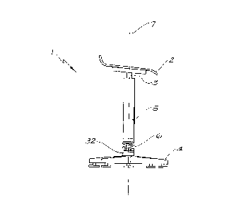
Un chaise (1) comprend un siège (2) couplé à un tube de montage (3) présentant un axe de rotation (7), une base (4) et un raccord de tube permettant le pivotement dudit tube (3) par rapport à la base (4) autour de l'axe de rotation (7), et permettant l'inclinaison du tube (3) par rapport à une orientation verticale de la chaise (1) à divers degrés dans la direction du siège (4), et dans des directions latérales, empêchant le tube (3) de basculer dans une trop grande mesure dans la direction arrière du siège (2). Le raccord du tube comprend un support à ressort permettant la rotation et le basculement, il comprend une came montée sur le tube (3) limitant le degré de basculement selon la forme de la came.


Abrégé anglais


A chair (1) including a seat (2) coupled to a mounting shaft (3) having an
axis of rotation (7), a base (4) and a shaft coupling which allows the shaft
(3) to swivel relative to the base (4) about the axis of rotation (7) and
allows the shaft (3) to tilt relative to a vertical orientation of the chair
(1) to various degrees in the seat (4) direction and sideward directions and
prevents the shaft (3) tilting to any substantial extent in the seats (2)
rearward direction. The shaft coupling includes a spring bearing allowing the
rotation and tilting and includes a cam fitted on the shaft (3) which limits
the degree of tilting in accordance with the shape of the cam.

Revendications

Note : Les revendications sont présentées dans la langue officielle dans laquelle elles ont été soumises.


-5-
CLAIMS:
1. A chair including a seat coupled to a mounting
shaft having a longitudinal axis of rotation, a base,
and a shaft coupling which allows the shaft to swivel
relative to the base about the axis of rotation, and
allows the shaft to tilt relative to a vertical
orientation of the chair to various degrees in the
seat's forward direction and sideward directions and
prevents the shaft tilting to any substantial extent
in the seat's rearward direction.
2. A chair in accordance with claim 1 wherein the
shaft coupling includes a slewing bearing fitted
between the shaft and the base allowing the swivel
action and tilting action, and the degree of tilting
is limited by stop means on the shaft abutting the
base.
3. A chair in accordance with any preceding claim
wherein the stop means on the shaft includes a cam
fitted to the shaft which defines the allowable
pattern of tilting in accordance with the shape of
the cam.
4. A chair in accordance with any preceding claim
wherein the chair includes a resilient means biasing
the shaft in a substantially vertical orientation.
5. A chair in accordance with claims 3 wherein the
resilient means is a coil spring enveloping at least
a portion of the shaft.

Description

Note : Les descriptions sont présentées dans la langue officielle dans laquelle elles ont été soumises.


CA 02244813 1998-07-27
W O 97/:'7785 ~CT/AU97/00034
SWIVELLnNG AND TILTDNG C~kAIR
~K~.ROUND OF T~E l~V~:N'l'lON
5 In some environments the m~)v.- ~nt of a seated occupant
includes a reaching movement while re~ining seated,
such as a seated worker on a production line.
Some chairs are provided with a swivel action which
10 may on]y partly assist the seated occupant in the
re~--hi ng ~v~~ ~nt while other chz~irs may }:e provided
with castors which allow movement of the whole chair
which may be cumbersome in some situations.
15 If the reaching movement is repetitive or frequent,
these t:wo degrees of freedom of IllovG...cnt may not be
appropxiate for some seated occupants leading to
uncomfortable resching movements, accompanied by a bad
sitting posture during the mov.- ~nt, which may lead to
20 problems with the back.
SUMMARY OF THE lNV~NllON
The invention provides a chair including a seat, a
25 mounting shaft, a shaft coupling, and a base, wherein
the mounting shaft is coupled to the base so the
mounting shaft may swivel and may ti~t to various
degrees in a forward and sideward direction and is
prevented from tilting in a rearward direction to any
30 substantial extent.
A preferred embodiment of the invention provides a
chair that includes a seat fixed to a mounting shaft
that is coupled to a base by means of a slewing
35 coupling. The coupling is configured to allow tilting
of the seat and mounting shaft relative to the base
from a substantially vertical axis. Preferably the

CA 02244813 1998-07-27
W O 97/2778S PCT/~U97/0~034
--2--
coupling is configured to prevent the seated occupant
tilting the seat in a rearward direction in relation
to the seated occupant, and the coupling includes a
cam which defines the range and pattern of tilt.
Additionally the coupling may be configured to al~ow
swivelling of the seat and mounting shaft.
The mounting shaft also may be biased to a
substantially vertical position by a resilient means
such as a spring, to assist the seated occupant to
maintain an upright seated position, and to assist in
the return of the seat to an upright position at the
end of a reaching movement by the seated occupant.
BRIEF DESCRIPTION OF THE DRAWINGS
The invention will now be descri~ed ~y way of example
with reference to an embodiment illustrated in the
accompanying drawings, in which:
Fig. 1 is an illustration of a chair embodying the
invention biased in an upright position;
Fig. 2 is an illustration of a chair embodying the
invention in a tilted position;
Fig. 3A is a part cross sectional view of a coupling
suitable for coupling the mounting shaft and
base of the chair depicted in Fig. 1; and
Fig. 3B is a plan view of a cam suitable for use
in the coupling depicted in Fig. 3A.
DESCRIPTION OF THE PREFERRED EMBODIMENTS
3~
The chair 1 in Figs. 1 and 2 includes a seat 2 fixed
to a mounting shaft 3 which is enveloped by a shaft

CA 02244813 1998-07-27
W O 97/:'7785 PCT/AU97/00034
. --3--
column 5 and coupled to a base fitting 32 on a base 4
by means of a coupling 34 illustrated in Figs. 3A and
3B. The shaft column 5 is fixed to the mounting shaft
3 to prevent the shaft column 5 rotating relative to
J 5 the mounting shaft 3.
The chair 1 is provided with a coil spring 6 which
biases the seat 2 and mounting shaft 3 to an upright
position as illustrated in Fig. 1 and depicted by a
vertical axis 7. The seat 2 and mounting shaft 3 may
be tilted relative to the vertical axis 7 as
illustrated by a tilted axis 20 in Fig. 2, against
the bias exerted by the coil spring 6. If the tilting
force exerted by a seated occupant (not shown) is
removed, then ~he seat 2 and the mounting shaft 3 will
return to an upright position depicted by the vertical
axis 7 in Fig. 1 and 2.
~he coupling 34 in Fig. 3A couples the mounting shaft
3 to the base fitting 32 by means of a rod end bearing
31 allowing rotation and slewing of the mounting shaft
3 relative to the base fitting 32. The degree and
pattern of slewing of the mounting shaft 3 relative to
the base fitting 32 is predetermined by a cam 33 fixed
to the mounting shaft 3.
The coil spring 6 is engaged with the base fitting 32
and a thrust race 30 fitted to the shaft column 5.
The thrust race 30 provides bearing assisted rotation
of the shaft 3 relative to the base fitting 32.
~ The illustrated cam 33 will prevent a seated occupant
(not shown) on the chair 1 tilting the seat 2 to a
substantial extent in a rearward direction. For this
3~ purpose the lobe portion of the cam surface 35 is
orientated towards the front of the seat 2, so that
upon rearward tilting of the chair it will contact an

CA 02244813 1998-07-27
W O 97/27785 PCT/AU97/00034 --4--
inner surface of the base fitting 32 thereby
restricting or prohibiting rearward titling of the
seat 2 and the mounting shaft 3. On the other hand,
the r~ining surface of the cam 33 will allow more
extensive forward and sideways tilting or combined
forward and sideways tilting.
Therefore in use a chair in accordance with the
invention may tilt within predetermined limits and
pattern, while being free to swivel thereby assisting
a seated occupant during a reaching ~ve...ent.
In a further contribution to the ergonomics of the
chair in its preferred form, the seat 2 is tilted
forwardly to throw more of the seated occupant's
weight onto the seated occupant's feet than would
occur if the seat was substantially horizontal. The
seated occupant's feet will thus form a tripod with
the chair, providing a stable base for the seated
occupant~s sitting position and reaching -,v. ?nts.
It is to be understood that the invention has been
described with reference to an embodiment only for
the purpose of illustration and is not intended to be
confined to that embodiment.

Dessin représentatif
Une figure unique qui représente un dessin illustrant l'invention.
États administratifs

2024-08-01 : Dans le cadre de la transition vers les Brevets de nouvelle génération (BNG), la base de données sur les brevets canadiens (BDBC) contient désormais un Historique d'événement plus détaillé, qui reproduit le Journal des événements de notre nouvelle solution interne.

Veuillez noter que les événements débutant par « Inactive : » se réfèrent à des événements qui ne sont plus utilisés dans notre nouvelle solution interne.

Pour une meilleure compréhension de l'état de la demande ou brevet qui figure sur cette page, la rubrique Mise en garde , et les descriptions de Brevet , Historique d'événement , Taxes périodiques et Historique des paiements devraient être consultées.

Historique d'événement

Description Date
Inactive : CIB de MCD 2006-03-12
Demande non rétablie avant l'échéance 2005-09-16
Inactive : Morte - Aucune rép. dem. par.30(2) Règles 2005-09-16
Réputée abandonnée - omission de répondre à un avis sur les taxes pour le maintien en état 2005-01-21
Inactive : Abandon. - Aucune rép dem par.30(2) Règles 2004-09-16
Inactive : Dem. de l'examinateur par.30(2) Règles 2004-03-16
Inactive : Grandeur de l'entité changée 2004-01-28
Modification reçue - modification volontaire 2002-12-16
Inactive : Correspondance - Poursuite 2002-06-21
Lettre envoyée 2001-10-15
Inactive : Grandeur de l'entité changée 2001-07-05
Lettre envoyée 2001-05-14
Inactive : Transfert individuel 2001-04-10
Exigences pour une requête d'examen - jugée conforme 2001-04-10
Toutes les exigences pour l'examen - jugée conforme 2001-04-10
Requête d'examen reçue 2001-04-10
Inactive : CIB attribuée 1998-10-23
Symbole de classement modifié 1998-10-23
Inactive : CIB attribuée 1998-10-23
Inactive : CIB en 1re position 1998-10-23
Inactive : Notice - Entrée phase nat. - Pas de RE 1998-10-08
Demande reçue - PCT 1998-10-05
Demande publiée (accessible au public) 1997-08-07

Historique d'abandonnement

Date d'abandonnement Raison Date de rétablissement
2005-01-21

Taxes périodiques

Le dernier paiement a été reçu le 2003-12-30

Avis : Si le paiement en totalité n'a pas été reçu au plus tard à la date indiquée, une taxe supplémentaire peut être imposée, soit une des taxes suivantes :

  • taxe de rétablissement ;
  • taxe pour paiement en souffrance ; ou
  • taxe additionnelle pour le renversement d'une péremption réputée.

Les taxes sur les brevets sont ajustées au 1er janvier de chaque année. Les montants ci-dessus sont les montants actuels s'ils sont reçus au plus tard le 31 décembre de l'année en cours.
Veuillez vous référer à la page web des taxes sur les brevets de l'OPIC pour voir tous les montants actuels des taxes.

Historique des taxes

Type de taxes Anniversaire Échéance Date payée
Taxe nationale de base - générale 1998-07-27
Enregistrement d'un document 1998-07-27
TM (demande, 2e anniv.) - générale 02 1999-01-21 1998-07-27
TM (demande, 3e anniv.) - générale 03 2000-01-21 1999-12-08
TM (demande, 4e anniv.) - générale 04 2001-01-22 2001-01-12
Enregistrement d'un document 2001-04-10
Requête d'examen - petite 2001-04-10
TM (demande, 5e anniv.) - petite 05 2002-01-21 2001-10-05
TM (demande, 6e anniv.) - petite 06 2003-01-21 2002-09-24
TM (demande, 7e anniv.) - générale 07 2004-01-21 2003-12-30
Titulaires au dossier

Les titulaires actuels et antérieures au dossier sont affichés en ordre alphabétique.

Titulaires actuels au dossier
CLAITEAL PTY LTD
Titulaires antérieures au dossier
RONALD CHARLES HIBBERD
Les propriétaires antérieurs qui ne figurent pas dans la liste des « Propriétaires au dossier » apparaîtront dans d'autres documents au dossier.
Documents

Pour visionner les fichiers sélectionnés, entrer le code reCAPTCHA :


Pour visualiser une image, cliquer sur un lien dans la colonne description du document. Pour télécharger l'image (les images), cliquer l'une ou plusieurs cases à cocher dans la première colonne et ensuite cliquer sur le bouton "Télécharger sélection en format PDF (archive Zip)" ou le bouton "Télécharger sélection (en un fichier PDF fusionné)".

Liste des documents de brevet publiés et non publiés sur la BDBC .

Si vous avez des difficultés à accéder au contenu, veuillez communiquer avec le Centre de services à la clientèle au 1-866-997-1936, ou envoyer un courriel au Centre de service à la clientèle de l'OPIC.


Description du
Document 
Date
(aaaa-mm-jj) 
Nombre de pages   Taille de l'image (Ko) 
Dessin représentatif 1998-10-26 1 3
Description 1998-07-26 4 153
Abrégé 1998-07-26 1 48
Revendications 1998-07-26 1 36
Dessins 1998-07-26 3 33
Avis d'entree dans la phase nationale 1998-10-07 1 192
Courtoisie - Certificat d'enregistrement (document(s) connexe(s)) 1998-10-07 1 114
Courtoisie - Certificat d'enregistrement (document(s) connexe(s)) 2001-05-13 1 113
Rappel - requête d'examen 2001-09-23 1 129
Accusé de réception de la requête d'examen 2001-10-14 1 194
Courtoisie - Lettre d'abandon (R30(2)) 2004-11-24 1 167
Courtoisie - Lettre d'abandon (taxe de maintien en état) 2005-03-20 1 174
PCT 1998-07-26 11 352
Correspondance 2001-06-12 2 88
Correspondance 2002-09-23 1 68