Note : Les descriptions sont présentées dans la langue officielle dans laquelle elles ont été soumises.
CA 02245640 1998-08-21
NETWORK MANAGEMENT SYSTEM WITH NETWORK DESIGNING FUNCTION
BACKGROUND OF THE INVENTION
1. Field of the invention
The present invention generally relates to a network
management system, and in particular to system and method which
manage the network based on the capabilities and operation states
of network components.
2. Description of the Related Art
There has been disclosed an example of a conventional
network management system in Japanese Patent Unexamined
Publication No. 8-328984. According to the conventional system,
the network information regarding the capabilities and operation
states of network components is collected from the existing
network using a management protocol such as SNMP ( Simple Network
Management Protocol). The collected network information is
stored onto a network database. In the case where the network
is modified on demand, a simulation of the modified network is
performed using the network database prior to actually making a
modification to the existing network. In this manner, it can be
determined in advance whether the simulation of the modified
network provides the expected performance. If the modified
network is good in the simulation, the modification is made to
CA 02245640 1998-08-21
FQ5-322
the existing network.
However, if the simulation of the modified network does not
provide acceptable performance, it is necessary for a network
manager to redesign the modification of the network and then to
perform the simulation of the redesigned network again. This is
a time-consuming and inefficient procedure.
SUN~lARY OF THE INVENTION
An object of the present invention is to provide network
management system and method which can automatically perform the
redesign of a network in response to user's demands.
Another object of the present invention is to provide
management system and method which can automatically produce an
optimal plan for updating the settings of network components.
According to the present invention, network information of
the network is stored for retrieval and, when inputting a plurality
of demands each for a change of performance of the network, a
modified design of the network is provided based on the network
information to satisfy the demands.
An initially-modified design of the network may be produced
by determining a minimum-cost route for each of the demands , and
then the initially-modified design may be optimized to produce
the modified design by changing the minimum-cost route for each
of the demands so that cost of modification of the network is
CA 02245640 2005-02-14
75372-18
3
minimized as a whole.
Since the modified design of the network is
provided based on the network information to satisfy the
demands, optimal performance and configuration management to
satisfy the demands can be automatically obtained.
According to a first broad aspect, the invention
provides a method for providing management of a network,
comprising the steps of: a) storing network information of
the network for retrieval; b) inputting a plurality of
demands each for a change of performance of the network; and
c) providing a modified design of the network based on the
network information to satisfy the demands by c-1) producing
an initially-modified design of the network by determining a
minimum-cost route for each of the demands, the minimum cost
routes for each of the demands being summed to produce a
total cost of the initially-modified design of the network;
and c-1-i) selecting one of the demands in decreasing order
of increase in performance bandwidth; and c-1-ii) producing
the initially-modified design of the network by determining
a minimum-cost route for a first selected demand, and by
c-2) optimizing the initially-modified design to produce the
modified design by changing the minimum-cost route for each
of the demands so as to minimize the total cost of the
modified design of the network by c-2-i) selecting one of
the demands in decreasing order of amount of cost decrease
which would be caused by removing a demand from the
initially-modified design; and c-2-ii) removing a second
selected demand from the initially-modified design to
produce a temporary design; and producing the modified
design by determining a minimum-cost route for the second
selected demand based on the temporary design.
CA 02245640 2005-02-14
75372-18
3a
According to a second broad aspect, the invention
provides a method for providing management of a network
comprising the steps of: a) storing network information of
the network for retrieval; b) inputting a plurality of
demands each for a change of performance of the network
wherein each of the demands specifies two network elements
and a required amount of traffic between the two network
elements; and c) providing a modified design of the network
based on the network information to satisfy the demands by
c-1) determining a first route between the two network
elements for each of the demands to produce a set of first
routes in the network, wherein the first route provides
minimum cost of changing settings of network elements
between the two network elements included; and c-2) changing
the first route to a second route between the two network
elements for each of the demands based on the set of first
routes so that the second route provides minimum network
cost of changing settings of network elements between the
two network elements included.
According to a third broad aspect, the invention
provides a system for providing management of a network,
comprising: a storage for storing network information of the
network for retrieval; an input device for inputting a
plurality of demands each for a change of performance of the
network; and a network designer for providing a modified
design of the network based on the network information to
satisfy the demands, wherein each of the demands specifies
two network elements and a required amount of traffic
between the two network elements, the network designer
determines a first route between the two network elements
CA 02245640 2005-02-14
75372-18
3b
for each of the demands to produce a set of first routes in
the network, and wherein the first route provides minimum
cost of changing settings of network elements between the
two network elements included, and then changes the first
route to a second route between the two network elements for
each of the demands based on the set of first routes so that
the second route provides minimum network cost of changing
settings of network elements between the two network
elements included.
According to a fourth broad aspect, the invention
provides a method for providing management of a network,
comprising the steps of: a) storing network information of
the network for retrieval; b) inputting a plurality of
demands each for a change of performance of the network; and
c) producing an initially-modified design of the network by
determining a minimum-cast route for each of the demands; d)
selecting one of the demands in decreasing order of amount
of cost decrease which would be caused by removing a demand
from the initially-modified design; e) removing a second
selected demand from the initially-modified design to
produce a variable network design; f) producing a modified
design by determining a minimum-cost route for the second
selected demand based on the variable network design; and g)
repeating the steps d) to f) to minimize total cost of the
modified design of the network based on the variable network
design.
BRIEF DESCRIPTION OF THE DRAWINGS
Fig. 1 is a block diagram showing a network
management system according to a first embodiment of the
present invention;
CA 02245640 2005-02-14
75372-18
3c
Fig. 2 is a diagram showing a schematic
configuration of a network for explanation an operation of
the embodiment;
Fig. 3A is a diagram showing a cost function with
respect of required bandwidth for each link connecting two
adjacent nodes;
Fig. 3B is a diagram showing a cost function with
respect of increase in bandwidth in the case where a 7-Gbps
switch or a 20-Gbps switch is introduced to a node in place
of a 5-Gbps switch;
Fig. 4 is a flow chart showing a schematic
operation of the network designing section;
Fig. 5 is a flow chart showing an initial
determination
CA 02245640 1998-08-21
FQ5-322
routine performed by the network designing section;
Fig. 6 is a flow chart showing a route optimization routine
performed by the network designing section;
Fig. 7 is a block diagram showing a network management system
according to a second embodiment of the present invention;
Fig. 8 is a block diagram showing a network management system
according to a third embodiment of the present invention; and
Fig . 9 is a block diagram showing a network management system
according to a fourth embodiment of the present invention.
DETAILED DESCRIPTION OF THE PREFERRED EMBODIMENTS
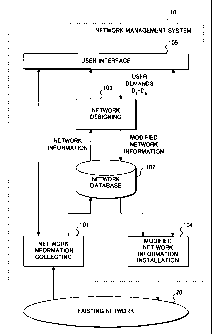
Referring to Fig. 1, a network management system 10
according to an embodiment of the present invention collects
performance and other information about the existing network 20
or about particular nodes on the network 20. Further, the network
management system 10 performs network redesigning on user demands
and network information installation as will be described
hereinafter.
The network management system 10 is provided with a network
information collecting section 101 which collects at least
CA 02245640 1998-08-21
FQ5-322
information required for network redesigning from the existing
network 20 or particular nodes on the network 20. The network
information includes configuration information, that is, states,
settings, capabilities about nodes and links and topology
information and may further include traffic information
indicating the level of network activity in the network 20 or in
each link. The collected network information is stored onto a
network database 102 for later retrieval.
The network management system 10 is further provided with
a network designing section 103 which inputs the collected network
information from the network database 102 and redesigns the
network so as to satisfy the user demands received from the user
interface 105 . The network designing section 103 may be comprised
of a program-controlled processor, a read-only memory storing a
network designing program, and a memory for storing input user
demands, network information and other information. These
circuit blocks are not shown in Fig. 1.
The modified network information including modified
settings, capabilities and other data about nodes and links is
stored onto the network database 102 and a modified network
information installation section 104 writes or installs the
modified network information into nodes of the network 20.
Since the network information collecting section 101 and
the modified network information installation section 104 have
been known, the details are omitted. The user interface 105 may
be comprised of an input device, a monitor for displaying necessary
CA 02245640 1998-08-21
FQ5-322
information, and other devices. The input device is used to input
various instructions such as network information collecting
instruction, network information installation instructions,
network designing instruction and further to input user demands .
As shown in Fig. 2, consider for simplicity that a network
consisting of four nodes NODE1-NODE4 is operating with initial
settings of the nodes. For example, in the case of occurrence
of a demand D(1,4) specifying two nodes NODE1 and NODE4 and a
requested bandwidth, it is necessary to modify the settings and
capabilities of nodes and links of a selected route between NODE1
and NODE4 to allow communications of the requested bandwidth.
Such modification causes an increase in cost for each node and
link . As shown in Fig . 2 , a cost increase of a NODE ( i ) is indicated
by O C ( i ) and a cost increase of a LINK ( i , j ) between NODE ( i ) and
NODE(j) is indicated by O C(i,j). The details of cost increase
will be described hereinafter.
Referring to Fig . 3A, consider that NODE ( i ) and NODE ( j ) are
provided with a switch having a capacity of bandwidth Wo and then
a bandwidth WD wider than Wo is demanded of that node . To satisfy
the requirement of the bandwidth Wp, the NODE ( i ) and NODE ( j ) must
be upgraded to at least the capacity of bandwidth Wp. Introducing
the higher-capacity switch causes a node cost increase indicated
by O C = D C ( i ) + O C ( j ) according to a cost curve 301 .
In general , since it is the same with a LINK ( i , j ) between
them, a cost increase is indicated by O C = O C(i) + O C(j) + 0
C ( i , j ) . In the case where one of the nodes has already satisfied
CA 02245640 1998-08-21
FQ5-322
the demand, the corresponding cost increase 0 C(i) or O C(j) is
zero. Similarly, when the link has already satisfied the demand,
the corresponding cost increase D C(i,j) is zero.
To describe more specifically, assuming that the node is
equipped with a 5-Gbps switch and the capacity of the node can
be upgraded to 7-Gbps or 20-Gbps by replacing the 5-Gbps switch
with the 7-Gbps or 20-Gbps switch or by adding an extended module
to the 5-Gbps switch. And further assuming that a bandwidth of
3 Gbps has been occupied, resulting in an available bandwidth of
2 Gbps left in that node.
In this case , as shown in Fig . 3B , the node can accommodate
an increase in bandwidth up to 2 Gbps without the need of additional
cost. When a bandwidth increase due to the demand is more than
2 Gbps and not more than 4 Gbps, the 7-Gbps switch is introduced
to the node, so that the cost increases to the introduction cost
C,~. When a bandwidth increase due to the demand is more than 4
Gbps and not more than 17 Gbps, the 20-Gbps switch is introduced
to the node, so that the cost further increases to the introduction
cost CZO~~ Therefore, the cost function for each node is a
step-like function 302 depending on the existing capacity and
activity of the node.
As described before, in the case of the demand D(1,4) as
shown in Fig. 2, there are four possible route candidates as
follows:
1) first route candidate: NODE1-NODE2-NODE3-NODE4,
2) second route candidate: NODE1-NODE2-NODE4,
CA 02245640 1998-08-21
FQ5-322
3) third route candidate: NODE1-NODE3-NODE4, and
4) fourth route candidate: NODE1-NODE3-NODE2-NODE4.
Among the four possible route candidates, an optimal route is
selected with respect to cost increase. Assuming that a cost
increase in two adjacent nodes NODE(i) and NODE(j) and the
LINK(i,j) is represented by 0 C = 0 C(i) + 0 C(j) + 0 C (i,j) and
a network cost increase in all nodes included in a selected route
for each demand DI is represented by O CNT and, the first route
candidate costs a network cost increase 0 CNTl = 0 C ( 1 ) + O C ( 2 ) +
OC(3) + OC(4) + OC(1,2) + OC(2,3) + OC(3,4), the second route
candidate costs a network cost increase 0 Cr,,l,z = O C ( 1 ) + 0 C ( 2 ) +
O C(4) + O C(1,2) + O C(2,4), the third route candidate costs a
network cost increase OC~,z,3 = ~C(1) + OC(3) + OC(4) + OC(1,3)
+ O C(3,4), and the fourth route candidate costs a network cost
increase ~C~,,~,4 = OC(1) + ~C(3) + ~C(2) + OC(4) + OC(1,3) + 0
C(2,3) + OC(2,4).
There is selected an optimal route having the minimum
network cost increase. For example, when the second route
candidate is the optimal route, the respective settings and
capabilities of NODE1, NODE 2 and NODE4 and LINK( 1, 2 ) and LINK( 2 , 4 )
are modified to allow communications of the requested bandwidth.
Such an optimal route can be searched for using well-known Dijkstra
algorithm (see "Algorithms" written by Robert Sedgewick, second
edition, Addison Wesley, pp.461-465).
NETWORK DESIGNING
The network designing section 103 inputs the collected
CA 02245640 1998-08-21
FQ5-322
network information from the network database 102 and redesigns
the network so as to satisfy the user demands . The minimum cost
route is obtained by solving a kind of minimum cost flow problem
in a network. Therefore, even though the respective optimal
routes satisfying a plurality of demands are obtained, a
combination of the optimal routes is not always the optimal
solution for the whole network. Then, according to the present
invention, the network designing section 103 first performs a
local minimum cost route determination procedure and then a
whole-network minimum cost route determination procedure.
Referring to Fig. 4, upon receipt of N user demands D1-
DN from the user interface 105 , the network designing section 103
performs an initial determination procedure which determines the
minimum-cost route for each demand which is selected in decreasing
order of requested bandwidth (step S401).
Subsequently, the network designing section 103 performs
a route optimization procedure which optimizes the initially-
determined routes so that the total network cost increase is
reduced to the minimum value ( step 5402 ) . As will be describer,
a network cost increase is minimized by removing each demand from
the network and determining a minimum-cost route for the removed
demand in the state of the network from which the demand has been
removed. Thereafter, it is determined whether the total network
cost increase is minimized and, if it is not minimized, the route
optimization steps are repeatedly performed until the total
network cost increase is minimized. In this manner, the optimal
CA 02245640 1998-08-21
FQ5-322 1 0
modification of the network information can be obtained. The
details will be described hereinafter.
INITIAL DETERMINATION
Referring to Fig. 5, when receiving N user demands D1-DN
from the user interface 105, the network designing section 103
stores the N user demands D1-DN onto a memory and sorts them in
decreasing order of requested bandwidth to produce the sorted
demands D~°'1-D~°'N ( step 5501 ) . After a variable I is
initialized
( step 5502 ) , a demand D~°'I is read from the memory ( step 5503 )
and
then cost increases ~C~°'I of possible route candidates which would
be caused by the selected demand D~°'I are calculated as described
before referring to Fig. 2 and Figs . 3A and 3B ( step S504 ) . Among
the possible route candidates, the minimum-cost increase route
R~°'I is searched for as an optimal route using the Dijkstra
algorithm (step 5505).
Thereafter, the settings of the nodes and links forming the
minimum-cost increase route R~°'I are modified to satisfy the demand
D~°'I ( step S506 ) . The initially-modified network information
is
temporarily stored onto the memory. It is determined whether the
variable I reaches N (step 5507) and, if not, the variable I is
incremented by one ( step 5508 ) , then control goes back to the step
5503. The steps S503-5508 are repeatedly performed until the
variable I reaches N (YES in step S507). In this manner, the
initially-modified network information including the respective
minimum-cost increase routes R~°'1-R~°'N for all the sorted
demands
D~°'1-D~°'N are obtained and stored in the memory.
CA 02245640 1998-08-21
FQ5-322 1 1
ROUTE OPTIMIZATION
Subsequently, the network designing section 103 performs
the route optimization procedure which optimizes the
initially-determined routes R~°'1-R~°'N so that the total
network
cost increase is minimized.
First , the network designing section 103 sorts the N user
demands in a different way from the step 5501 of the initial
determination procedure. After a variable I is initialized (step
5601 ) , a demand DI is read from the memory ( step 5602 ) . Then the
network designing section 103 removes the demand DI from the
initially-modified network information stored in the memory and
calculates a network cost decrease 0 Cr,,l, ( I ) which would be caused
by removing the selected demand DI ( step 5603 ) . It is determined
whether the variable I reaches N (step 5604) and, if not, the
variable I is incremented by one (step 5605), then control goes
back to the step 5602. The steps S602-5605 are repeatedly
performed until the variable I reaches N (YES in step S604).
In this manner, the respective network cost decreases D
CN,i, ( 1 ) - O CNT ( N ) for all the demands D1-DN are obtained . Thereafter
,
the network designing section 103 sorts the N user demands D1-DN
in decreasing order of network cost decrease to produce the sorted
demands D~1~1-D~1~N ( step 5606 ) .
Subsequently, after a variable I is initialized ( step 5607 ) ,
a demand D~l~i is read from the memory. Then the bandwidths and
other settings of the nodes and links associated with the demand
D~1~I are removed from the initially-modified network information
CA 02245640 1998-08-21
FQ5-322 1 2
to produce a changed network information ( step 5608 ) . Under this
condition, the demand D~l~i is input again. As described before,
cost increases OC~l~i of possible route candidates which would be
caused by the demand D~l~i are calculated (step 5609) . Among the
possible route candidates, the minimum-cost increase route R~l~i
is searched for as an optimal route using the Dijkstra algorithm
(step S610).
Thereafter, the settings of the nodes and links forming the
minimum-cost increase route R~1'I are modified to satisfy the demand
D~1~I and the modified network information is stored onto the memory
(step S611). It is determined whether the variable I reaches N
( step S612 ) and, if not , the variable I is incremented by one ( step
5613), then control goes back to the step S608. The steps
S608-5613 are repeatedly performed until the variable I reaches
N (YES in step 5612). In this manner, the modified network
information including the respective minimum-cost increase
routes R~1~1-R~1~N for all the sorted demands D~1~1-D~1~N are obtained
and stored in the memory.
Thereafter, if the variable I reaches N (YES in step S612) ,
then it is determined whether the total network cost increase is
minimized ( step S614 ) and the route optimization steps 5601-5613
are repeatedly performed until the total network cost increase
is minimized. In this manner, the optimal modification of the
network information can be obtained and the modified network
information is output to the network database 102.
Variations of the network management system 10 are shown
CA 02245640 1998-08-21
FQ5-322 1 3
in Figs. 7-9. In Fig. 7, the system 10 is provided with a
controller 701 which controls the network information collecting
section 101, the network database 102, the network designing
section 103 , and the network information installation section 104 .
Further the controller 701 is provided with a communication means
for communicating the existing network 20. Since the functions
and operations of these sections are the same as in Fig. 1, the
descriptions are omitted.
In Fig. 8, the system 10 has the same configuration as in
Fig. 1 but the network information installation section 104. In
this embodiment, the network information installation is
performed offline. Contrarily, the system 10 as shown in Fig.
9, the system 10 has the same configuration as in Fig. 1 but the
network information collecting section 101. In this embodiment ,
the network information of the existing network 20 is collected
offline.