Note : Les descriptions sont présentées dans la langue officielle dans laquelle elles ont été soumises.
CA 02247763 1998-09-15
COMBINE HARVESTER ROTOR LOAD CONTROL
Technical Field:
This invention relates to combine harvesters and more
particularly to a control system that controls ground speed to maintain a
constant load on the threshing rotor.
Background Of The Invention
The grain threshing, separating and cleaning assemblies of a
combine harvester operate at maximum efficiency only if there is a
substantially constant crop material feed rate. A change in the feed rate of
grain, or the feed rate of crop material other than grain affects the
operation
of the threshing, separating and cleaning assemblies. The standard
adjustments found on harvesting machines make it possible to accommodate
and harvest a variety of crops under a variety of crop and weather conditions.
However, it takes time and skill to make these adjustments. A change in the
quantity of material passing through a combine harvester can substantially
change the efficiency of the harvesting operation even if the weather and
crop conditions remain unchanged.
A decrease in the quantity of crop material passing through
the threshing cylinder or rotor and concave can result in a substantial
increase
in the quantity of cracked grain. Cracked grain is blown out of the harvester
and on to the ground by the cleaning system fan.
An increase in the quantity of crop material passing through a
harvester can overload the cleaning system, form a mat of crop material on
the sieve of the chaffer and a large portion of the threshed grain will end up
on the ground rather than in the grain tank. An increase in the quantity of
CA 02247763 1998-09-15
P-304 WCC 2
crop material passing through a harvester can also overload the separating
assemblies and cause grain loss.
Combine harvesters are designed to handle close to the
maximum capacity of the threshing assembly, separating assembly and
cleaning assembly, and the power source at any given time. To do this, the
capacity of each of the assemblies and the power source must be balanced
with each other. Due to variations in crop conditions and weather conditions,
it is not possible to attain a perfect balance between the threshing,
separating
and cleaning assemblies and the power source. In practice operators
generally adjust the threshing, separating and cleaning assemblies for a crop
material feed rate which leaves sufficient power available to propel the
combine with the current field conditions and to unload the grain tank. The
operator then varies the grounds speed of the harvester as best he can to
maintain a constant crop material feed rate. Experienced combine operators
can maintain crop material feed rates within a range that attains satisfactory
threshing, separating and cleaning. However, due to operator fatigue, even
experienced operators fail to maintain crop material feed rates within an
acceptable range after several hours of operation without a rest period.
Systems that maintain a constant load on a harvester internal
combustion engine by controlling harvester ground speed have been tried.
Some of these systems sense engine load through the engine governor and
adjust harvester ground speed to maintain engine load within a narrow range.
CA 02247763 1998-09-15
P-304 WCC 3
When a field to be harvested is dry and flat, the engine load control can
maintain a fairly constant crop material feed rate. Hills or slopes in a field
can vary the power required to propel a combine harvester through the field
to such an extent that an engine load based control system is rendered
unacceptable for controlling crop material feed rate.
A field with hard, compact soil in some areas and soft soils in
other areas will have variable power requirements for propelling a combine
harvester through the field. This variation in the total engine load can
result
in an engine load based control system making large changes in ground speed
and unacceptable changes in crop material feed rates.
Attempts have been made to measure the load on combine
harvester threshing cylinders and employ the measured load to control crop
material feed rates. Measurement of the load on the threshing cylinder has
been difficult. A system based on the creep of a cylinder drive belt in the
driven and driving pulleys or sheaves worked well. However, if the cylinder
drive belt becomes over loaded and actually slips, the system fails to control
crop material feed rate. For a belt drive based system to measure threshing
cylinder load to control crop material feed rate, the belt drive must be
capable
of transmitting more torque than will be required, to avoid belt slip. Such
belt drives are expensive and are generally not available on high-capacity
combine threshing cylinder drives.
CA 02247763 1998-09-15
P-304 WCC 4
SUMMARY OF THE INVENTION
An object of the invention is to control crop material feed rate
in a combine harvester by controlling harvester ground speed. Another
5 object of the invention is to control combine harvester ground speed based
on
threshing and separating rotor drive power requirements. A further object of
the invention is to control combine harvester ground speed by sensing the
pressure of hydraulic fluid entering a hydraulic motor driving the threshing
cylinder and sending signals to the traction drive to adjust ground speed and
10 thereby maintaining the crop material feed rate within a selected range.
The combine harvester has an axial flow threshing and
separating rotor. A rotor hydraulic pump is driven by an internal combustion
engine that powers the harvester. A rotor hydraulic motor is driven by
hydraulic fluid from the rotor pump and drives the threshing and separating
15 rotor. A traction drive hydraulic pump is also driven by the internal
combustion engine. A traction drive hydraulic motor is driven by a hydraulic
fluid from the traction drive pump and drives the driven ground engaging
wheels through a gear transmission.
An Electronic controller monitors the pressure of hydraulic
20 fluid entering the hydraulic motor. This pressure is proportional to the
power
required to drive the rotor. The controller has an adjustable rotor pressure
selector that is manually set. The controller compares the set pressure of the
pressure selector with the sensed pressure of hydraulic fluid entering the
rotor
CA 02247763 1998-09-15
P-304 WCC 5
hydraulic motor. If the two pressures differ more than a predetermined
amount, the controller sends a signal to the traction drive pump to adjust the
swash plate position and thereby change the harvester ground speed. If the
measured pressure of hydraulic fluid entering the rotor hydraulic motor is
less than the selected set pressure, more than a predetermined amount, the
controller will send a signal to the solenoid control valve on the traction
drive
hydraulic pump to move the swash plate to a position that will increase the
stroke of the pump pistons, increase hydraulic fluid flow and increase
harvester ground speed. The increased ground speed will increase the crop
material feed rate which will increase the power required to rotate the rotor
and increase the pressure of hydraulic fluid entering the hydraulic motor.
The controller will send a signal to the solenoid control valve on the
traction
drive hydraulic pump to move the swash plate to a position which will
decrease the stroke of the pump pistons when the measured pressure of
hydraulic fluid entering the rotor hydraulic motor is more than the selected
set pressure by more than a predetermined amount. The decrease in the
stroke of the pump pistons decreases hydraulic fluid flow and decreases
harvester ground speed. The decreased ground speed will decrease the crop
material feed rate which will decrease the power required to rotate the rotor
and decrease the pressure of hydraulic fluid entering the rotor hydraulic
motor.
The maximum ground speed of the combine harvester is set
manually by the operator. The controller can decrease the harvester ground
CA 02247763 1998-09-15
P-304 WCC 6
speed from the manually set ground speed. The controller can also increase
the ground speed up to the maximum speed set manually by the operator.
The controller described above is an electronic controller. A
hydro mechanical controller can also be employed. The hydro mechanical
5 controller control system includes a pressure override control valve that
controls the pressure of hydraulic fluid supplied to the traction drive pump
control valve. The traction drive pump control valve supplies hydraulic
pressure to servo pistons that control the position of the traction pump swash
plate. The pressure override control valve is a spool valve with an end biased
10 by a spring and the other end biased by hydraulic fluid under pressure from
the rotor motor hydraulic fluid inlet. The spring is manually loaded to set
the
pressure of hydraulic fluid supplied to the rotor drive motor. When the
pressure of hydraulic fluid at the rotor motor hydraulic fluid inlet changes,
the spool valve changes the position of the traction pump swash plate and
15 thereby returns the crop material feed rate to the selected feed rate.
BRIEF DESCRIPTION OF THE DRAWINGS
The foregoing and other objects, features and advantages of
20 the present invention will become apparent in the light of the following
detailed description of exemplary embodiments thereof, as illustrated in the
accompanying drawing.
CA 02247763 1998-09-15
P-304 WCC 7
Figure 1 is a side elevational view of combine harvester
separator with parts broken away;
Figure 2 is a schematic plan view of a combine harvester and
harvester drive components;
5 Figure 3 is a schematic view of a combine harvester threshing
rotor load control system;
Figure 4 is a schematic view of the rotor drive;
Figure 5 is a schematic view of the traction drive;
Figure 6 is a schematic view of the traction drive pump; and
10 Figure 7 is an enlarged view of the pressure override control
valve in a combination with the traction drive manual control valve.
DESCRIPTION OF THE PREFERRED EMBODIMENT
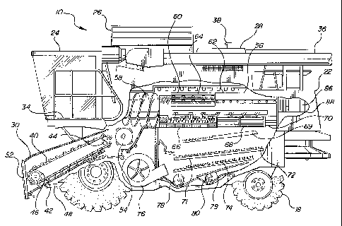
The combine harvester, generally designated by reference no.
15 10, is self propelled. The combine frame 12 is supported by two front
driven
wheels 14 and 16 and rear steered wheels 18 and 20. The wheels 18 and 20
could be also driven if desired. The frame 12 could also be supported by a
full track system or by half tracks. Half tracks would replace the driven
wheels 14 and 16 only.
20 The combine 10 has a separator housing 22 mounted on the
frame 12, an operator's work station and cab 24 mounted on the front portion
of the frame, a grain tank 26, an engine compartment 28 and an elevator
assembly 30. A ladder 32 and cab access platform 34 provide operator
CA 02247763 1998-09-15
P-304 WCC 8
access and egress to and from the cab 24. A swingable unloading auger
assembly 36 pivots to a position extending laterally outward to one side of
the combine 10 to unload the grain tank 26. The unloading auger assembly
36 swings inward to a storage position shown in Figures 1 and 2 when the
5 grain tank 26 is not being unloaded. The engine compartment 28 houses an
internal combustion engine 38 mounted on the frame 12 above the separator
housing 22 and to the rear of the grain tank 26.
The elevator assembly 30 has a conveyor 40 mounted in an
elevator housing 42. The conveyor 40 as shown in Figure 1 is trained around
10 rear drive sprockets 44 and a front drum 46. Pivot assemblies (not shown)
pivotally attach the elevator housing 42 to the frame 12 for pivotal movement
about the axis of the drive sprockets 44. Hydraulic linear actuators 48 pivot
the elevator housing 42 to raise and lower the forward end of the housing.
Headers 50 attach to the forward end surface 52 of the elevator housing 42.
15 These headers 50 can be grain headers which sever crop material from the
ground, pick-up headers which lift crop material from the ground, corn heads
and other various headers designed for specific crops. All of these headers
50 gather crop material and feed the crop material to the conveyor 40. The
conveyor 40 conveys crop material into the separator housing 22.
20 Crop material is fed to the feed beater 54 by the conveyor 40
in the elevator housing 42. The beater 54 feeds crop material to an axial flow
threshing and separating rotor 56. The rotor 56 as shown in Figure 1 has a
feed section 58, a threshing section 60, and a separation section 62. The feed
CA 02247763 1998-09-15
P-304 WCC 9
section 58 moves crop material in a spiral path about the generally horizontal
fore and aft axis of rotation to the rotor 56, toward the threshing cylinder
section 60 and generally parallel to the axis of rotation of the rotor. In the
threshing cylinder 60, crop material passes between the cylinder bar 64 and a
concave 66 where the grain is threshed. Threshed grain, that is not separated
by the concave 66, is separated in the separation section 62 and passes
through the separation grate 68. The grain pan 69 conveys grain and chaff
forward and deposit it on the chaffer 72. Crop material other than grain is
discharged from the rotor 56 through the rotor discharge 70.
Grain and crop material other than the grain that passes
through the concave 66 and the separation grate 68 falls to an upper grain pan
69. The grain pan 69 conveys grain and chaff forward and deposit it on the
chaffer 72. The grain is cleaned by a chaffer 72 and a sieve 74 and air from a
fan 76. Chaff is discharged from the rear of sieve 74 and chaffer 72. Clean
grain falls into the clean grain auger 78 and is conveyed to the clean grain
auger by a lower grain pan 73. The clean grain is conveyed to the grain tank
26 by the auger 78 and an elevator (not shown). Tailings fall into the returns
auger 80 and are conveyed to the rotor 56 by the returns auger and a returns
elevator (not shown). where they are threshed a second time.
The threshing and separating rotor 56 as described above, is
referred to as an axial flow threshing rotor because crop material is moved in
a direction generally parallel to the axis of rotation of the rotor. Combine
threshing cylinders that receive crop material tangentially and discharge crop
CA 02247763 1998-09-15
P-304 WCC 10
material tangentially are also used. In these harvesters, the cylinder
generally
rotates about an axis that is perpendicular to the path of movement of the
material.
The internal combustion engine 38 mounted in the engine
compartment 28 drives a rotor pump 82 and a traction drive pump 84. The
rotor pump 82 drives a rotor hydraulic motor 86. The rotor hydraulic motor
86 drives the threshing and separating rotor 56 through a planetary reduction
gear train in a gear box 88. A supply line 90 and return line 92 connect the
rotor pump 82 and the rotor motor 86 to each other in a closed circuit.
Leakage of hydraulic fluid in the pump 82 and the motor 86 is returned to the
sump. Make up of hydraulic fluid is supplied to the return side of the rotor
pump 82 from the sump S by a make-up fluid pump 94. The pump 94
maintains a pressure of 350 pounds per square inch on the return side of the
rotor pump 82.
The traction drive pump 84 is connected to a traction drive
motor 96 by a supply line 98 and a return line 100. The motor 96 drives a
transmission 102. Gear trains and a differential in the transmission 102 drive
a right side drive shaft 104 and a left side drive shaft 106. A speed
reduction
gear box 108 transmits torque from the drive shaft 104 to the driven wheel
16. The driven wheel 14 is driven by the drive shaft 106 through a speed
reduction gear box 110.
The supply line 98 and the return line 100 connect the traction
drive pump 84 and the traction drive motor 96 together in a closed loop
CA 02247763 1998-09-15
P-304 WCC 11
hydraulic system. Leakage of hydraulic fluid in the pump 84 and the motor
96 is returned to a sump S. The make-up fluid pump 95 supplies made up
hydraulic fluid to the return side of the traction drive pump 84 and maintains
a pressure of 350 pounds per square inch on the return side of the pump 84.
5 The torque required to drive the rotor 56 of a combine
harvester 10 is proportional to the pressure of hydraulic fluid entering the
rotor motor 86. The torque required to drive the rotor 56 is also proportional
to the quantity of crop material passing through the rotor. By maintaining a
substantially constant fluid pressure at the entry of hydraulic fluid into the
10 rotor motor 86, a substantially constant crop material flow rate through
the
threshing and separating rotor 56 is attained. The crop material flow rate
into
a harvester 10 is also proportional to the width of the header, the forward
speed of the harvester and the density of crop material to be harvested by the
harvester . The density of crop material varies across a field to be harvested
15 due to differences in soil conditions, rainfall, fertilization, drainage,
slope
relative to the sun, and other factors. By changing the forward speed of the
harvester 10 it is possible to accommodate variations in crop material density
in a field and obtain a substantially uniform crop material feed rate through
a
crop threshing mechanism 56. A skilled operator can manually adjust
20 forward speed and reduce the variations in crop material feed rate.
However,
manual control of harvester ground speed to control crop material feed rate is
inaccurate, takes the attention of the harvester operator away from other
critical duties, and leads to operator fatigue.
CA 02247763 1998-09-15
P-304 WCC 12
An electronic rotor load control generally designated 120 is
provided to simultaneously reduce the work load of the harvester operator,
reduce grain loss and increase the quantity of grain harvested per hour. The
rotor load control 120 includes an electronic controller 122, a manually
5 adjustable control potentiometer 124 for selecting the desired thresher
rotor
set point and an on and off switch 126. A pressure transducer 127, that
measures the pressure of hydraulic fluid entering the rotor motor 86 is
mounted on the rotor motor and connected to the electronic controller 122. A
solenoid control valve 128 is mounted on the traction pump 84, to control the
10 position of the traction pump swash plate 210, and is connected to the
electronic controller 122. An engine speed sensor 130 is mounted on the
harvester 10 in a position to sense the rotational speed of the engine 38 and
is
connected to the electronic controller 122.
During operation of the harvester 10, the operator moves the
15 on and off switch 126 to an on position to engage the rotor load control
120.
The electronic controller 122 receives sensed pressures from the pressure
transducer 127 and compares the actual pressure sensed by the pressure
transducer to the pressure set point provided by the adjustable control
potentiometer 124. When the actual pressure of hydraulic fluid entering the
20 rotor motor 86 varies more that a predetermined amount from the set point
of
the potentiometer 124, the electronic controller 122 sends a signal to a
solenoid control valve 128 to move the swash plate 129 of the traction pump
84 and change the speed of the traction motor 96. If the actual pressure
CA 02247763 1998-09-15
P-304 WCC 13
sensed by the transducer 127 is less than the set point of the potentiometer
124 by more than a predetermined amount, the electronic controller 122 will
increase ground speed to increase crop material feed rate. If the actual
pressure sensed by the pressure transducer 127 is more than the set point of
5 the potentiometer 124 by more than a predetermined amount, the electronic
controller 122 will decrease ground speed to decrease crop material feed rate.
Preferably the ground speed of the harvester 10 is changed in incremental
steps. There is a time lag between the time there is a change in ground speed
and a change in the rotor load resulting from the ground speed change.
10 Incremental steps reduce the tendency to make larger speed changes than
necessary. Pressure comparisons are made several times per minute by the
controller 122 to keep up with changes in crop material feed rate.
The rotor load control system 120 makes it possible in good
crop and field conditions to operate the harvester at a crop material feed
rate
1 ~ that uses almost all of the power available from the internal combustion
engine 38 of the harvester 10. If the operator attempts to unload the grain
tank 26 into a truck moving alongside the harvester 10, or if the surface of
the field which the harvester is travelling upon becomes softer for example,
there can be a dramatic increase in the power required. This increase in the
20 power required will frequently overload the engine 38. When more power is
required then the engine 38 can provide, the engine will start to slow down.
The decrease in the engine speed, detected by the engine speed sensor 130, is
transmitted to the electronic controller 122. Upon detection of an overloaded
CA 02247763 1998-09-15
P-304 WCC 14
engine 38, the electronic controller 122 will override the rotor load control
portion of the controller 120 and decrease forward speed of the harvester 10
to prevent the engine from stalling. As soon as the speed of the engine 38
returns to the normal operating range, the rotor load controller 122 will
5 resume control of the speed of the harvester. If the engine overload
condition
continues, the operator will have to reduce the set point pressure with the
adjustable control potentiometer 124 to a pressure which permits the
electronic controller 122 to control the forward speed of the harvester 10
based on rotor motor inlet hydraulic fluid pressure measured by the pressure
10 transducer 127.
The crop material feed rate control system described above is
described in combination with a threshing and separating rotor 56 that moves
crop material in a spiral path around the axis of the rotor. The system is for
use on a harvester 10 that employs a hydraulic motor 86 to drive the rotor 56.
1 S Combine harvesters with threshing cylinders that rotate around an axis
transverse to the direction of crop material movement through the cylinder
and concave could also employ the crop material feed rate control if the
cylinder is driven by a hydraulic motor 86.
The speed of rotation of a threshing cylinder driven by a
20 hydraulic motor 86 tends to change with temperature. As the temperature of
the hydraulic oil increases, the speed tends to decrease. A constant cylinder
or rotor speed control system that maintains a substantially constant cylinder
CA 02247763 1998-09-15
P-304 WCC 15
or rotor speed can be used in combination with the load control system
described above.
The crop material feed rate control described above is an
electronic control system. A mechanical and hydraulic control system can
5 also be employed. The crop material feed rate system shown in Figures 6
and 7 is a mechanical and hydraulic control system. The pumps 82 and 84
and the motors 86 and 96, shown in Figures 4 and 5 are the same in the
mechanical and hydraulic control system as they are in the electronic control
system described above.
10 The pumps 82 and 84 are preferably axial piston pumps with
swash plates as shown in Figure 6. The swash plates are adjustable, as
described below, to adjust the output speed of the motors 86 and 96 driven by
the pumps 82 and 84. The motors 86 and 96 are also preferably axial piston
motors with swash plates. The swash plates for the motors 86 and 96 can be
15 either fixed or adjustable. If the swash plates are adjustable, the
adjustment
can be one that shifts the swash plates between a high speed range and a low
speed range. The adjustment of swash plates in the motors 86 and 96 can
also be coordinated with adjustment of the swash plates in the pumps 82 and
84 to obtain improved efficiency of each pump and motor combination.
20 Although the pumps and motors are preferably axial piston units with swash
plates, as set forth above, other types of motors could be used. It would also
be possible to use other types of pumps.
CA 02247763 1998-09-15
P-304 WCC 16
The traction drive pump 84 has had an input shaft 202
journaled in a pump casing 204 and driven by the internal combustion engine
38. As rotor 206 on the shaft 202 rotates with the shaft and carries a
plurality
of axial pistons 208, the pistons 208 contact a swash plate 210. The swash
5 plate 210 forces the pistons 208 into their bores in the rotor 206 and
forces
hydraulic fluid out. The swash plate 210 is pivotally mounted in the casing
204 for pivotal movement about a transverse horizontal axis that passes
through the input shaft 202. Servo pistons 212 and 214 pivot the swash
plate 210 to control the stroke of the pistons 208 and the direction of fluid
10 flow.
Leakage of hydraulic fluid in the traction drive motor 96 is
returned to the casing 204 of the pump 84 through a line 216. Hydraulic
fluid leakage in the casing 204 is drained through a discharge line 218 that
delivers the hydraulic fluid to a sump S. A fluid make-up pump 94 draws
15 hydraulic fluid from the sump S through a suction line 220 and delivers the
fluid to the return line 100 or the supply line 98 through check valve 222 or
check valve 224 shown in Figure 6. The fluid make-up pump 94 supplies
hydraulic fluid at 350 psi. The check valve 222 opens and lets fluid from the
make-up pump 94 enter the piston bores in the rotor 206 when the pressure
20 in the return line 100 is less than 350 psi. The pressure of fluid in the
return
line 100 forces the piston 208 toward the swash plate 210 and fills the piston
bores. The~check valve 224 remains closed when the pressure of fluid in
supply line 98 is above 350 psi. Pivotal movement of the swash plate 210,
CA 02247763 1998-09-15
P-304 WCC 17
from the position in which the servo piston 212 is retracted and the servo
piston 214 is extended, will change the supply line 98 to a return line and
will
change the return line 100 to a supply line. These changes reverse the flow
of fluid to the motor 96 and reverse the motor output shaft. The fluid make-
5 up pump 94 also supplies fluid to the control valve 226 through a control
fluid line 228.
The control valve 226, which is mounted on the pump casing
204, is a spool valve with a spool 230. When the spool 230 is centered, the
swash plate 210 remains in a substantially fixed position and no hydraulic
10 fluid is passed from the valve 226.. When the spool 230 moves to the right
as shown in Figure 6, hydraulic fluid, from the pump 94 and line 228, passes
to the servo piston 214 through the line 232 and fluid is free to move from
the servo piston 212 through to line 234 and to the sump S. When the spool
230 moves to the left as shown in Figure 6, hydraulic fluid, from the pump 94
15 and line 228, passes to the servo piston 212 through the line 234 and fluid
is
free to move from the servo piston 214 through the line 232 to the sump S.
Hydraulic fluid which enters the valve 226 through the line 2 32 passes
through a passage 231 (shown in Figure 7) in a spool 230 to reach the sump.
The spool 230, as shown in Figure 6, is pivotally connected to the center of a
20 bell crank 236 by a pivot pin 238. The upper end of the bell crank 236 is
connected to an arm 240 on a manually controlled shaft 242 by connecting
rod 244. The shaft 242 is manually pivoted by a boden wire 246 with one
end attached to an arm 241 on the shaft 242. The other end of the boden wire
CA 02247763 1998-09-15
P-304 WCC 18
246 is connected to a manual control lever 250. The control lever 250 has a
full speed forward position F, a neutral position N, and a full speed reverse
position R as shown in Figure 6. The lower end of the bell crank 236 is
attached to the swash plate 210 by the followup linkage indicated by the
5 phantom line 252. When the lever 250 is moved, the spool 230 supplies
hydraulic fluid to one of the servo pistons 212 or 214 until the swash plate
210 moves to its new position corresponding to the position of the lever 250.
The spool 230 is returned to a position, in which the flow of hydraulic fluid
to both servo pistons 212 and 214 is blocked, by the followup linkage 252
10 and the bell crank 236 as a swash plate 210 moves to a position that
corresponds to a position of the lever 250. A manually set position of the
lever 250 controls the direction of rotation of the traction drive motor 96 as
well as the speed of rotation.
A crop material feed rate control valve 254 is positioned
15 between the control valve 226 and the pump casing 204 when the harvester
10 is equipped with a mechanical and hydraulic control system. The crop
material feed rate control valve 254 has a spool 256 that is biased to the
right
as shown in Figure 7 by a compression spring 258. The compression spring
is tensioned by a piston 260 that contacts a rotatable cam 262. The cam 262
20 is manually rotated by a lever arm 264, and linkage 266 and a rotor load
control adjustment lever 268 located near the operator's work station. The
other end of the spool 256 is biased to the left by a piston 270 in a bore
272.
The bore 272 is connected to hydraulic fluid at the pressure of hydraulic
fluid
CA 02247763 1998-09-15
P-304 WCC 19
in the supply line 90 at the inlet port of the rotor motor 86 by pipe fitting
271
and a line.
The pump 94 and the control fluid line 228 supply hydraulic
fluid to the port 273 in the feed rate control valve 254. When the spring 258
5 is biasing the spool 256 to the right as shown in Figure 7, fluid entering
port
273 is supplied to the spool 230. A spool 230 will hold the pressure of
hydraulic fluid supplied to one of the servo pistons 212 or 214 to maintain
harvester ground speed and crop material feed rate if the force exerted by the
spring 258 is equal to or greater than the force exerted by the piston 270.
10 When the force exerted on the spool 256 by the piston 270,
due to the pressure of hydraulic fluid in the bore 272 connected to the supply
line 90 for the rotor motor 86, exceeds the force exerted by the spring 258,
the spool 256 moves to the left as shown in Figure 7 and passage 273 is
connected to the port 278 and the casing 204. Leakage from the port 276
15 past the spool 230 allows hydraulic fluid to flow out of the servo piston
212
thereby destroking the pump 84. Destroking the pump 84 decreases forward
speed of the harvester 10. The decrease in forward speed generally decreases
crop material feed rate. The lever 250 controls maximum forward speed and
will override the system when the selected feed rate can not be obtained at
20 the maximum forward speed selected by the operator.
An increase in the crop material feed rate will increase the
pressure of hydraulic fluid entering the rotor motor 86. The increase in
pressure entering the rotor motor 86 increases the pressure of hydraulic fluid
CA 02247763 1998-09-15
P-304 WCC 20
in the bore 272. Excess pressure in the bore 272 causes the piston 270 to
move the spool 256 to the left and compress the spring 258. The spool 256
then closes the port 273 and opens the port 278, which is connected to the
inside of the casing 204 and the sump S by the line 218. Reducing the
pressure of hydraulic fluid supplied to the spool 230 allows hydraulic fluid
to
pass from the port 276 and the servo piston 212 to the port 278 and to the
sump S. The ground speed will decrease until the force exerted on the spool
256 by hydraulic fluid and the piston 270 equals the force exerted by the
spring 258. When these forces are balanced, the spool 256 will move to the
10 right thereby opening the port 273 and closing the port 278. The pressure
of
hydraulic fluid supplied to the spool 230, through the port 273, will maintain
pressure in the port 276 and hold the swash plate 210 in place, thereby
maintaining harvester ground speed and crop material feed rate.
The lever 268 located in the cab 24 is used by the operator to
15 set the maximum crop material feed rate through the rotor 56 by limiting
the
pressure to the motor 86. The lever 250, located in the cab 24 is used by the
operator to set the maximum forward speed of the harvester 10. The operator
can stop forward movement of the harvester 10 with the lever 250 and can
also move the machine in reverse. The operator cannot however, increase
20 forward speed and crop material feed rate above the crop material feed rate
setting of the lever 268. The lever 268 can prevent the threshing rotor 56
from being overloaded. The lever 250 can prevent the grounds speed of the
harvester 10 from exceeding the maximum speed desired by the operator.
CA 02247763 1998-09-15
P-304 WCC 21
Applicant's co-pending U.S. Patent Application, the disclosure
of which is incorporated herein by reference, is directed to a threshing rotor
speed control system. This rotor speed control system can be used together
with the crop material feed rate controls described above. The disclosed
5 embodiments are representative of presently preferred forms of the
invention,
but are intended to be illustrative rather than definitive thereof. The
invention is defined in the claims.