Sélection de la langue

Search

Sommaire du brevet 2253966 

Énoncé de désistement de responsabilité concernant l'information provenant de tiers

Une partie des informations de ce site Web a été fournie par des sources externes. Le gouvernement du Canada n'assume aucune responsabilité concernant la précision, l'actualité ou la fiabilité des informations fournies par les sources externes. Les utilisateurs qui désirent employer cette information devraient consulter directement la source des informations. Le contenu fourni par les sources externes n'est pas assujetti aux exigences sur les langues officielles, la protection des renseignements personnels et l'accessibilité.

Disponibilité de l'Abrégé et des Revendications

L'apparition de différences dans le texte et l'image des Revendications et de l'Abrégé dépend du moment auquel le document est publié. Les textes des Revendications et de l'Abrégé sont affichés :

  • lorsque la demande peut être examinée par le public;
  • lorsque le brevet est émis (délivrance).
(12) Brevet: (11) CA 2253966
(54) Titre français: INTERRUPTEUR DE CIRCUIT A BLINDAGE TERMINAL ET CONDUIT DE FILERIE
(54) Titre anglais: CIRCUIT INTERRUPTER WITH TERMINAL SHIELD AND WIRE TROUGH
Statut: Durée expirée - au-delà du délai suivant l'octroi
Données bibliographiques
(51) Classification internationale des brevets (CIB):
  • H01H 09/02 (2006.01)
  • H01H 71/08 (2006.01)
(72) Inventeurs :
  • CHONTAS, TRENT A. (Etats-Unis d'Amérique)
  • MAYHOOD, KEITH L. (Etats-Unis d'Amérique)
  • LATHROP, TODD M. (Etats-Unis d'Amérique)
(73) Titulaires :
  • EATON INTELLIGENT POWER LIMITED
(71) Demandeurs :
  • EATON INTELLIGENT POWER LIMITED (Irlande)
(74) Agent: BERESKIN & PARR LLP/S.E.N.C.R.L.,S.R.L.
(74) Co-agent:
(45) Délivré: 2007-03-27
(22) Date de dépôt: 1998-11-12
(41) Mise à la disponibilité du public: 1999-05-13
Requête d'examen: 2003-11-03
Licence disponible: S.O.
Cédé au domaine public: S.O.
(25) Langue des documents déposés: Anglais

Traité de coopération en matière de brevets (PCT): Non

(30) Données de priorité de la demande:
Numéro de la demande Pays / territoire Date
08/969,557 (Etats-Unis d'Amérique) 1997-11-13

Abrégés

Abrégé français

Un disjoncteur ou interrupteur sous boîtier moulé dont les bornes CHARGE ou LIGNE sont protégées par un dispositif de blindage des bornes multifonctionnel qui offre également les cloisons interphases pour les bornes susmentionnées et le câblage connexe. La cloison offre également des goulottes pour les fils supplémentaires à basse tension.


Abrégé anglais

A molded case circuit breaker or switch having the LOAD and/or LINE terminals thereof protected by a multifunctional terminal shield arrangement which also provides interphase barriers for the aforementioned terminals and associated wiring. The barrier also provides wire channels for lower voltage supplemental wiring.

Revendications

Note : Les revendications sont présentées dans la langue officielle dans laquelle elles ont été soumises.


6
We claim:
1. Switching apparatus for an electric power circuit comprising:
a switch housing;
a switching device mounted in said switch housing;
power terminals for connecting said switching device to said
electric power circuit mounted in spaced relation at an end face of said
switch
housing;
an attachment device connected in said housing to said
switching device and having external leads exiting said switch housing
adjacent said power terminals;
a terminal shield means interconnected with said housing
adjacent said power terminals for shielding said power terminals;
said terminal shield means having interphase barriers
separating said power terminals one from the other; and
said interphase barriers having a longitudinally extending
passage through which said electrical leads are routed.
2. Switching apparatus as claimed in claim 1, wherein said shield
means has a wire trough therein disposed between said longitudinally
extending passage and said end face.
3. Switching apparatus as claimed in claim 2, wherein said trough
is oriented ninety degrees offset relative to said longitudinal passage.
4. Switching apparatus for an electric power circuit comprising:
a switch housing;
a switching device mounted in said switch housing;
power terminals for connecting said switching device to said
electric circuit mounted in spaced relation at an end face of said switch
housing;

7
leads exiting said switch housing adjacent to but not connected
to said power terminals;
a terminal shield means interconnected with said housing
adjacent said power terminals for shielding said power terminals;
said terminal shield means having interphase barriers
separating said lower terminals one from the other; and
said interphase barriers having a longitudinally extending
passage through which said electrical leads are routed.

Description

Note : Les descriptions sont présentées dans la langue officielle dans laquelle elles ont été soumises.

CA 02253966 2006-05-03
1
CIRCUIT INTERRUPTER WITH TERMINAL SHIELD AND WIRE TROUGH
BACKGROUND OF THE INVENTION
Field of the Invention
The subject matter of this invention is related generally to molded case
circuit breakers and more particularly to terminal shield arrangements for
molded case circuit breakers.
Description of the Prior Art
Molded case circuit breakers are known generally in the art. As an
example, U.S. Patent 4,644,120 entitled "Molded Case Circuit Breaker with a
Movable Lower Electrical Contact Positioned by a Torsion Spring" issued
February 17, 1987 and now transferred to the present assignee, teaches a
molded case circuit breaker of the kind having terminals at each end thereof
for
interconnection with load and line conductors of a given voltage which may be,
for example, voltages such as 120 or 240 volts ac. In addition there are
provided on many molded case circuit breakers openings or ports through
which relatively low voltage control or accessory wiring is provided. The
relatively low voltage accessory wiring, which may be 10, 12 or 40 volts for
example, is routed out of the molded case circuit breaker to other positions
for
providing electrical conductivity to and from the molded case circuit breaker.
One of the disadvantages of having the relatively low voltage control or
auxiliary wiring is the fact that it may be routed in or near the load or line
wiring

CA 02253966 1998-11-12
97-PDC-340
which is at a relatwely higher voltage. As can be appreciated, even though
the wires are insulated, having voltages of different values conducted by
conductors in close proximity to each may introduce an opportunity for short
circuit, flash over and other inadvertent electrical contact, etc. Thls would
be detrimental to either the load, line or the low voltage auxiliary elements
depending upon the circumstances. .
It would be advantageous therefore if a means could be provided,
which both shields the relatively high voltage terminals from outside contact
and which acts as a separate wire way or wire routing device for low voltage
or auxiliary voltage wiring, so that lower voltage and higher voltage can be
appropriately spaced.from each other by the insulation of the terminal shield
and wire way arrangement.
SUMMARY OF THE INVENTION
In accordance with the invention.a switching apparatus for an
electrical power circuit is taught. The switching apparatus includes a switch
housing and a switching device mounded within the switch housing. Power
terminals are provided for connecting the switching device to an electrical
circuit. The power terminals are at the face of the switch housing and
dispose in space relationship therein. An attachment device is connecting in
the housing to the switching device and has external leads exiting the switch
housing adjacent to power terminals. A terminals shield is provided which
is interconnected with the housing adjacent to the power temlinals for
shielding the power terminals and furthermore for having interphase barrier
therein for separating the power terminals, one from the other and finally for
having longitudinally extending passages therein through which the
aforementioned low voltage electrical leads are routed.
BRIEF DESCRIPTION OF THE DRAWNGS
Reference may be had to the preferred embodiment of the invention
shown in the accompanying drawings in which:
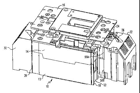
Fig. 1 shows a molded case circuit breaker and terminal shields in
orthogonal projection partially broken away with openings and terminals for
power leads and auxiliary leads and including slots for accepting the
terminal shield;

CA 02253966 2006-05-03
3
Fig. 2 shows the terminal shield of the present invention in orthogonal
view from the non-circuit breaker side thereof;
Fig. 3 shows an orthogonal view of the terminal shield of Fig. 2 from
the side which is normally interconnected with the circuit breaker;
Fig. 4 shows an orthogonal view of the molded case circuit breaker
with terminal shields fully in place on both ends thereof; and
Fig. 5 shows the circuit breaker and terminal shield arrangement of Fig.
4 in side elevation.
DESCRIPTION OF THE PREFERRED EMBODIMENTS
Referring now to Figure 1, molded case circuit breaker 10 with two
partially broken away end shields 32 is depicted. Molded case circuit breaker
10 is of the type shown and described in U.S. Patent 4,644,120 originally
assigned to the Westinghouse Electric Corporation and now assigned by
Agreement to the assignee of the present invention. In particular, molded
case circuit breaker 10 may include a lower housing 12 and an upper housing
14 which together join to form an enclosure for enclosing standard molded
case circuit breaker parts, such as trip mechanisms, operating mechanisms,
and separable main contacts all of which are described in the previously
mentioned incorporated-by-reference patent. There may also be provided a
top cover or auxiliary cover 16 which fits on top of the top portion 14.
Circuit
breaker 10 may include openings 18 on one end thereof and 20 on the other
end thereof which provide access to LOAD and LINE terminals 22 (not
shown). There may be also provided at least one opening 24 extended into
the internal region of the circuit breaker from which secondary, accessory or
low voltage control wiring 26 may extend. There are provided in the circuit
breaker case on the front and back (not shown) two longitudinal, stepped
openings 28 which may be utilized for mounting the terminal shield apparatus
32 in a manner which will be described herein after.
There is provided on the top of the case protruding through an opening
therein a handle 30 (see Figures 4 and 5). The handle 30 may be in the ON,
OFF or RESET state, depending upon the status of mechanisms within the
circuit breaker 10.

CA 02253966 1998-11-12
4 97-PDC-340
Referring now to Figures 2 and 3, there is shown a combination
terminal shield-interphase barrier and wire control channel or trough 32.
Shield arrangement 32 includes a set of parallel spaced apart side walls 34
and 42 which generally align with the sides of the circuit breaker 10 at the
ends thereof. There is provided a transverse barrier on back wall 36 joining
the side walls 34 and 32. Back wall 36 is generally parallel to the ends of
the circuit breaker 10. A canted wall portion 38 traverses the region
between the side walls 34 and 42 and joins the end region 36 with a
transverse top wall 40. Canted wall region 38 has slots or openings 39
therein which may be utilized to conduct heat away from the main terminals
22 (not shown) protected by the shield 32. There are provided in the
transverse panel or wall 36 openings 44 which extend from the bottom
thereof tv semicircular arc regions on the top. It is through these openings
44 that the main electrical conductors for the LOAD or the LINE terminals 22
may protrude after connection has been made. There is also shown two
interphase ban-iers 46 that separate the regions of the three conductors
which protrude through the openings 44, as would normally be he case in a
three phase electrical system. There are provided on the opposite side of
the shield from the end wall 36 two stepped longitudinal tabs 50 having a
first extending tab region 50A, a stepped down tab region 508, and a further
stepped down tab region 50C. Tabs 50A and B align with the corresponding
portions of openings 28 on the top 14 and bottom 12 of the molded case
circuit breaker, such that tab 50A extends into the top portion of the circuit
breaker 14 and tab 50B extends 'into the boftvm portion of the circuit breaker
12 as shown in Fig. 1. There also provided two wire control channels 52
which align with the openings 24,~ in the circuit breaker 10 for having
control
wires 26 feed therethrough to transverse openings 60 in the interphase
barriers 46, so that the wires may be routed through the transverse
openings 60 via channels 52 to the bottom of the shield 32 and outwardly to
control apparatus, power supplies, meters etc., for the low voltage wiring 26.
The presence of the control wiring 26 in the channel 52 and the wire troughs
60 isolates the low voltage control wiring from the high voltage line or load

" . ..
CA 02253966 2006-05-03
wiring which protrudes transversally through the openings 44 on the shield 32
for jointure to the LOAD or LINE terminals in the region 22 as the case may
be.
Referring now to Figures 4 and 5 the molded case circuit breaker 10 of
5 figure one is shown with two complimentary shield members 32 at each end
thereof to form the fully constructed, double shielded, molded case circuit
breaker arrangement depicted in Figures 4 and 5. With regard to Figures 4
and 5 the reference characters depicted therein are defined in Figures 1
through 3.
It is to be understood with respect to the embodiments of this invention,
that the shield arrangement is not limited to a 3-phase, ac shield
arrangements. Nor is it required that there be a shield arrangement at both
ends of the circuit interrupter as shown in Figures 4 and 5. It is also to be
understood that the shield arrangement may be utilized even if there is no
control wiring 26 present or if the control wiring 26 is utilized in a
different part
of the circuit breaker to follow a different exit route. It is also to be
understood
that the shield arrangement though described with respect to a molded case
circuit breaker may be utilized with any electrical apparatus in which it is
desired to shield the terminals thereof and/or provide interphase barriers
and/or provide alternate safe routing for wiring of a different voltage level
from
the main load wiring.
The apparatus taught herein has many advantages. One of the
advantages lies in the fact that a single shield arrangement may be utilized
to
provide the three fold function of: Main terminal protection, interphase
barrier
protection and alternate wiring channels for lower voltage wiring.

Dessin représentatif
Une figure unique qui représente un dessin illustrant l'invention.
États administratifs

2024-08-01 : Dans le cadre de la transition vers les Brevets de nouvelle génération (BNG), la base de données sur les brevets canadiens (BDBC) contient désormais un Historique d'événement plus détaillé, qui reproduit le Journal des événements de notre nouvelle solution interne.

Veuillez noter que les événements débutant par « Inactive : » se réfèrent à des événements qui ne sont plus utilisés dans notre nouvelle solution interne.

Pour une meilleure compréhension de l'état de la demande ou brevet qui figure sur cette page, la rubrique Mise en garde , et les descriptions de Brevet , Historique d'événement , Taxes périodiques et Historique des paiements devraient être consultées.

Historique d'événement

Description Date
Lettre envoyée 2019-02-06
Inactive : Périmé (brevet - nouvelle loi) 2018-11-12
Inactive : TME en retard traitée 2014-04-07
Lettre envoyée 2013-11-12
Accordé par délivrance 2007-03-27
Inactive : Page couverture publiée 2007-03-26
Préoctroi 2007-01-12
Inactive : Taxe finale reçue 2007-01-12
Un avis d'acceptation est envoyé 2006-10-31
Lettre envoyée 2006-10-31
Un avis d'acceptation est envoyé 2006-10-31
Inactive : Approuvée aux fins d'acceptation (AFA) 2006-09-01
Modification reçue - modification volontaire 2006-05-03
Inactive : CIB de MCD 2006-03-12
Inactive : Dem. de l'examinateur art.29 Règles 2005-11-25
Inactive : Dem. de l'examinateur par.30(2) Règles 2005-11-25
Modification reçue - modification volontaire 2004-01-23
Lettre envoyée 2003-11-18
Requête d'examen reçue 2003-11-03
Exigences pour une requête d'examen - jugée conforme 2003-11-03
Toutes les exigences pour l'examen - jugée conforme 2003-11-03
Inactive : Page couverture publiée 1999-05-26
Demande publiée (accessible au public) 1999-05-13
Inactive : CIB attribuée 1999-01-18
Inactive : CIB en 1re position 1999-01-18
Symbole de classement modifié 1999-01-14
Inactive : Certificat de dépôt - Sans RE (Anglais) 1998-12-30
Demande reçue - nationale ordinaire 1998-12-29

Historique d'abandonnement

Il n'y a pas d'historique d'abandonnement

Taxes périodiques

Le dernier paiement a été reçu le 2006-09-28

Avis : Si le paiement en totalité n'a pas été reçu au plus tard à la date indiquée, une taxe supplémentaire peut être imposée, soit une des taxes suivantes :

  • taxe de rétablissement ;
  • taxe pour paiement en souffrance ; ou
  • taxe additionnelle pour le renversement d'une péremption réputée.

Les taxes sur les brevets sont ajustées au 1er janvier de chaque année. Les montants ci-dessus sont les montants actuels s'ils sont reçus au plus tard le 31 décembre de l'année en cours.
Veuillez vous référer à la page web des taxes sur les brevets de l'OPIC pour voir tous les montants actuels des taxes.

Titulaires au dossier

Les titulaires actuels et antérieures au dossier sont affichés en ordre alphabétique.

Titulaires actuels au dossier
EATON INTELLIGENT POWER LIMITED
Titulaires antérieures au dossier
KEITH L. MAYHOOD
TODD M. LATHROP
TRENT A. CHONTAS
Les propriétaires antérieurs qui ne figurent pas dans la liste des « Propriétaires au dossier » apparaîtront dans d'autres documents au dossier.
Documents

Pour visionner les fichiers sélectionnés, entrer le code reCAPTCHA :


Pour visualiser une image, cliquer sur un lien dans la colonne description du document (Temporairement non-disponible). Pour télécharger l'image (les images), cliquer l'une ou plusieurs cases à cocher dans la première colonne et ensuite cliquer sur le bouton "Télécharger sélection en format PDF (archive Zip)" ou le bouton "Télécharger sélection (en un fichier PDF fusionné)".

Liste des documents de brevet publiés et non publiés sur la BDBC .

Si vous avez des difficultés à accéder au contenu, veuillez communiquer avec le Centre de services à la clientèle au 1-866-997-1936, ou envoyer un courriel au Centre de service à la clientèle de l'OPIC.

({010=Tous les documents, 020=Au moment du dépôt, 030=Au moment de la mise à la disponibilité du public, 040=À la délivrance, 050=Examen, 060=Correspondance reçue, 070=Divers, 080=Correspondance envoyée, 090=Paiement})


Description du
Document 
Date
(aaaa-mm-jj) 
Nombre de pages   Taille de l'image (Ko) 
Dessin représentatif 1999-05-25 1 17
Description 1998-11-11 5 224
Abrégé 1998-11-11 1 10
Revendications 1998-11-11 1 42
Dessins 1998-11-11 4 97
Description 2006-05-02 5 225
Revendications 2006-05-02 2 46
Dessins 2006-05-02 4 94
Dessin représentatif 2007-02-28 1 24
Courtoisie - Certificat d'enregistrement (document(s) connexe(s)) 1998-12-29 1 115
Certificat de dépôt (anglais) 1998-12-29 1 163
Rappel de taxe de maintien due 2000-07-12 1 109
Rappel - requête d'examen 2003-07-14 1 112
Accusé de réception de la requête d'examen 2003-11-17 1 173
Avis du commissaire - Demande jugée acceptable 2006-10-30 1 161
Avis concernant la taxe de maintien 2013-12-23 1 170
Quittance d'un paiement en retard 2014-04-06 1 163
Correspondance 2007-01-11 1 39