Note : Les descriptions sont présentées dans la langue officielle dans laquelle elles ont été soumises.
CA 022~7~73 1998-12-03
Herberts Gesellschaft mit beschrankter Haftung
Device for closing containers
The invention relates to a device for closing containers or
vessels such as cans or tins, for example for lacquers,
S which allows these containers to be sealed tightly.
A wide variety of closures is known for closing containers.
In particular, screw caps are normally used. Screw caps
equipped with a press-in seal are increasingly being used,
for example, for lacquer tins.
Furthermore, child-proof closures are used for vessels in
which solid or liquid products, for example cleaning agents
or hazardous liquids, are stored. These can be of various
designs. Closures are known, for example, in which the
vessel to be sealed has a thread at the orifice, beneath
which there are two recesses. The lid which can be screwed
onto this thread contains two extensions which engage in the
recess on closure. The closure lid can only be opened by
lateral pressure in the lid region.
In addition to child-proofing, it may also be necessary to
allow the vessels to be completely emptied and protected
from leakage. Vessels of this type are equipped, for
example, with an outlet nozzle or nozzle-shaped neck which
can be designed with varying degrees of flexibility
(G 92 06 318.7, DE 43 29 036). To guarantee that these
closures are child-proof, the neck and lid can have
detachably engaging teeth. To open the lid, the teeth first
have to be released by pressing specific flexible zones of
the neck or specific pressure points. The container can only
be opened after release of the teeth.
The above-mentioned closures can have the drawback that,
despite the relatively tight fastening of the closure on the
container, diffusion of filling components from the
container through the closure cannot be completely avoided.
CA 022~7~73 1998-12-03
This occurs, in particular, in the case of closures which
have relatively thin flexible walls. Filling components can
diffuse through them into the environment and, under certain
circumstances, can change the composition of the material in
the container and damage health with diffused solvent
vapour.
The object of the present invention is to provide a device
for closing a container, in particular a container
containing a liquid such as a coating medium, for example
lacquer, which prevents undesirable diffusion of filling
components from the container into the environment. This
device should also allow easy, complete emptying of the
container.
It has been found that this object is achieved by the device
forming a subject of the invention for closing a container
with a nozzle-shaped neck which is or can be fastened on the
container and is provided with a screw thread at its upper
end and with a lid which can be screwed thereon, which is
characterised in that the lid with a diameter range which is
greater than the diameter of the nozzle-shaped neck is
provided with a peripheral sealing tab.
According to a preferred development, the device according
to the invention can be designed so that, when the lid is
screwed home, the sealing tab rests on the upper face of the
container, on a projection formed on the upper face of the
container and/or on the part of the neck in contact with the
upper face of the container or the projection formed
thereon.
The device according to the invention therefore consists of
a lower part in the form of a nozzle-shaped neck for
fastening on a container orifice and a lid (screw lid, screw
cap) which can be screwed thereon, the rim of the lid being
equipped, for example, with a peripheral sealing tab. The
sealing tab, in its length, can contact the upper face of
CA 022~7~73 1998-12-03
the container or can rest thereon; it can also be applied
without contacting the upper face of the container. The
diameter of the screw lid equipped with the peripheral
sealing tab projects beyond the diameter of the neck located
on the container orifice.
It is advantageous if the peripheral sealing tab according
to the invention, for example, at the outer region of the
lid, in its length, is guided downwards in the direction of
the upper face of the container such that it rests
peripherally on the outer rim of the container orifice
without contacting the upper face of the container. For this
purpose, the normally horizontally or conically extending
upper face of the container can be provided, in the region
lS of the container orifice, with a projection, for example a
step, which forms, for example, the outer rim of the
container orifice.
The lower part of the peripheral sealing tab can be designed
in various ways, for example it can have narrowing in its
shape, for example furrows or bevels.
The peripheral sealing tab on the screw lid according to the
invention can also be so designed that it peripherally
contacts the upper face of the container and is supported
thereon. In the case of a small supporting face, the sealing
tab, with its outer edge, is guided down to the upper face
of the container such that it just contacts it. If the
sealing tab has a greater supporting face, it can be guided
so far down to the upper face of the container, for example,
that it is bent inward or outward and is supported on the
upper face when the lid is screwed on, as viewed from the
rim of the lid. The sealing tab can be flexible in design
for this purpose. The sealing tab can also be shaped, in its
lower portion, as a double tab, one edge of which contacts
the upper face of the container inwardly when the lid is
screwed on or rests on the upper face of the container while
the second edge is directed outwards.
CA 022~7~73 1998-12-03
The peripheral sealing tab can be arranged on the outer rim
of the lid if the diameter of the lid ls extended. The
extension can be arranged in the same plane as the upper rim
of the lid. It can also be bevelled or designed with an
offset from the upper lid rim. When the closure according to
the invention is pressed onto the container orifice, it
allows the lid to spring back in its outer region and
therefore creates less mechanical stress in the sealing tab
when the closure is pressed on. Furthermore, a grip for
better handling of the lid can be worked in the upper region
of the sealing tab at the level of the upper lid rim.
The sealing tab applied according to the invention can be
used for upper faces which extend horizontally and are also
bevelled, for example extend conically downwards or upwards,
or are bevelled, of containers.
The requirement for child-proofing of closures for
containers which contain hazardous substances such as
lacquer can be fulfilled by the sealing tab used according
to the invention. In the lower portion of the sealing tab,
for example, there can be provided internal axial sets of
teeth which are arranged in the interior of the sealing tab
either peripherally or at specific intervals, for example
opposite one another, e.g. in the form of 2 to 5 teeth.
Corresponding peripheral sets of teeth can then be located
on the neck of the device according to the invention, for
example in the portion directed toward the sealing tab. With
this development, the peripheral sealing tab with the teeth
arranged thereon moves over the peripheral teeth provided on
the neck on closure of the lid. Once the lid is closed, the
teeth of the sealing tab lie in the teeth of the neck. The
child-proofing must be releasable in design for opening the
lid. For example, the sealing tab can have unlocking systems
for this purpose. For example, the sealing tab can be
flexible in design so it can be pressed in. When the sealing
tab is pressed in at the positions of the teeth, the teeth
of the sealing tab can disengage from the peripheral teeth
CA 022~7~73 1998-12-03
on the lower part. The lid can then be unscrewed. The
opening of the lid is therefore permitted only when the lid
is moved simultaneously with disengagement of the child-
proofing.
With the device according to the invention for closing a
container, the nozzle-shaped neck can also be designed in
the form of flexible bellows. In particular, the invention
is also suitable for closures whose nozzle-shaped neck is
designed as press-in bellows. This allows the neck to be
collapsed and extended in the manner of bellows, for example
in the orifice of the container. The bellows-like neck can
be uniformly round in design. It is also possible to equip
the bellows with different wall thicknesses. For example,
the external form of the bellows can be annular while the
internal form is elliptical.
The bellows can also be stabilised by one or more central
ribs in the cross section of the bellows or by a peripheral
rib on the internal wall of the bellows. Rib-shaped
stabilisers of this type are known, for example from
EP-A-0 641 724. It is also possible to use bellows with a
peripheral rib on their external wall. The flexible design
of the bellows-like neck provides a further opportunity for
unlocking the above-described child-proofing, for example by
lateral pressure on the neck.
The neck of the closure device according to the invention
can be fastened on the container orifice in various ways.
For example, the lower end of the neck can be so designed
that it is pressed into the container orifice and, for
example, caught therein. The design of the neck at the level
of the container orifice is adapted to the rim of the
container orifice which is bent outwardly in the form of a
- 35 nozzle, for example, to form a projection, in such a way
that the lower part of the closure is guaranteed a secure
fit.
CA 022~7~73 1998-12-03
The neck of the closure can also be so designed that it can
be pressed on in order to fasten it. The lower part of the
neck can thus be, for example, cuff-shaped in design so it
covers from above the rim of the container orifice
comprising, for example, a projection. A development which
only partially surrounds the rim of the container orifice is
also possible.
When the rim of the container orifice is partially
surrounded by the neck of the closure device according to
the invention, the peripheral sealing tab at the lid rim
according to the invention can additionally have catches on
its interior toward the container rim. When the lid is
screwed on, these catches engage beneath the partial
surround and thus allow the sealing tab to rest closely on
the upper face of the container. This design is preferred in
closure devices with a bellows-like lower part.
With a bellows-like press-in neck, in particular, the
sealing tab of the lid can be designed as a horizontal
continuation of the upper lid rim so this continuation rests
on the container orifice on a cuff-like design of the
fastener of the neck when the lid is screwed on and the
bellows pressed in.
Additional sealing devices of various designs can be used to
enhance the sealing effect, in particular with closures
having a bellows-like neck.
For example, the bellows-like neck can be shortened so that
it is axially tensioned (bias) when the lid is screwed on
and the bellows pressed in. The lid together with the
peripheral sealing tab is thus pressed onto the portion of
the bellows surrounding the container rim. This bias is
permitted by shortening the upper edge of the bellows. The
lid is initially only partially screwed on, and the bellows
pressed in. As the lid is tightened, the bellows are
expanded so the lid is pulled downwards onto the container.
.. , . ~.. . .
CA 022~7~73 1998-12-03
The bellows preferably have flexible zones. A rigid
connection is achieved between lid and overlapping portion
of the bellows. The bellows can be shortened, for example,
by 1 to 2 mm.
In a further variation, the lid which can be screwed onto
the bellows-like neck can have a closure device on its
underside outside the threaded region but within the sealing
tabs applied according to the invention. These can be
grooves projecting downwards, for example from the underside
of the lid. The region of the neck covering the container
orifice in turn contains, for example, indentations for
receiving grooves in the lid. When the lid is screwed on and
the bellows are pressed in, the grooves are pressed into
these indentations and therefore produce a tight connection
between lid and neck. The grooves in the lid can be arranged
as desired in a regular sequence or irregularly. It is also
possible to provide, instead of the grooves, a continuous
rib which, when the bellows are pressed into a continuous
indentation, engages in the end of a bellows-like neck
surrounding the container rim.
In a further variation, the grooves or the continuous rib
can be so arranged on the underside of the lid outside the
lid thread but inside the sealing tab arranged according to
the invention, that the grooves press the bellows in their
lower portion against the container rim when the bellows are
pressed in. A tight connection between lid and lower part
can also be guaranteed in this way.
It is desirable if the sealing tab is flexible or elastic in
design. The elasticity of the peripheral sealing tab can be
guaranteed, for example, merely by the shaping of the tab.
The lid and neck of the closure device according to the
invention can consist, for example, of any plastics
materials. Material which is tight to permeation such as
HDPE, LDPE or LLDPE is particularly preferred.
CA 022~7~73 1998-12-03
The sealing tab can preferably consist of resilient
material. Close contact with the upper face of the container
is therefore permitted. Damage to the upper face of the
container is also thereby avoided when the device according
to the invention is pressed onto the container rim.
The lid material preferably consists of HDPE and the neck of
LDPE. Treatment of the material to improve the physical
properties, for example rigidity, permeation tightness, of
the lid material such as fluorination, sulphonation or
metallisation is possible.
With a bellows-like design of the neck of the closure device
according to the invention, the bellows can be rigid or
elastic. Bellows which can be collapsed and extended are
preferred. It is desirable if the bellows are formed from
elastic material so a proportion of the deformation energy
can be absorbed in the case of undesirable jerky mechanical
stress. According to a particular development, the material
is less flexible at the upper and lower end of the bellows
than in the intervening central portion.
The closure device according to the invention is suitable
for simple press-in closures and for press-in closures for
barrels which can be completely emptied.
The developments according to the invention are easy to
handle. The device can be so designed that brief pressure is
sufficient to ensure engagement of the neck with the screwed
on lid on or into the container rim. The sealing tab
arranged according to the invention on the outer lid rim
comes lnto effect in the manner described according to the
lnventlon.
In the case of the closure device according to the invention
with a bellows-like neck, engagement of grooves or a rib
which can be provided in the lid is permitted by application
of light pressure. In the development with the shortened
CA 022~7~73 1998-12-03
bellows, the bellows are automatically pulled toward the
container orifice when the bellows are pressed in.
The closure seal according to the invention avoids the risk
S of filling components such as steam or solvent vapours
escaping into the environment. A change in the composition
of the material in the container can therefore be avoided.
Furthermore, damage to health by the solvent vapours
diffusing into the environment of the container can be
avoided.
In particular, known bellows-type closures can rise in the
event of an increase in the internal pressure in the
container (for example during a rise in temperature) or in
the event of a reduction in external pressure (for example
with inadequate pressure compensation in air freight
traffic). With the closure seals according to the invention,
the covering effect is maintained at ambient temperatures of
up to 40~C insofar, in particular, as the bias compensates
the possible vapour tension of liquids poured into the
container.
Preferred embodiments of the closure device according to the
invention are illustrated in the accompanying drawings.
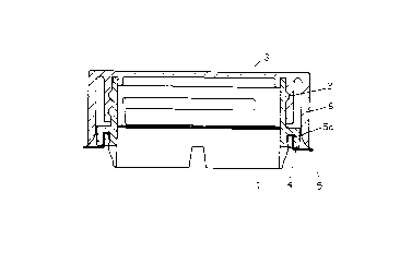
Fig. 1 shows a closure according to the invention with a
neck 1 provided with a screw thread 2 at its upper end. A
screw lid 3 is placed thereon. The neck 1 is pressed into a
curved orifice of a container 5. At the outer end of the lid
3 is a peripheral sealing tab 6 which, in the direction of
the upper face of the container 5, fits closely on the rim
of the orifice of the container 5 which is stepped in the
form of a projection 5a.
Fig. 2 shows a closure according to the invention with neck
1 and screw lid 3, the neck 1 having a cuff-shaped fastening
system 4 which is pressed over a projection 5a on the
orifice of the container 5. At the outer end of the lid 3 is
, . , . , . i , ., .~ . . .
CA 022~7~73 1998-12-03
a peripheral sealing tab 6 which is bevelled at the bottom,
extends to the upper face of the container 5 and places
itself externally thereon.
Fig. 3 shows a device according to the invention in the form
of a screw cap press-in closure with a bevelled region at
the outer rim of the lid 3 from which the peripheral sealing
tab 6 extends to the upper face of the container 5.
Fig. 4 shows a device accordlng to the invention in the form
of a screw cap press-in closure in which the peripheral
sealing tab 6 rests on a conically shaped upper face of the
container 5.
Fig. 5 shows a device according to the invention in the form
of a screw cap press-in closure with a peripheral sealing
tab 6 which is split in its lower portion and provided with
a furrow, forming an internal sealing edge 7 and an external
sealing edge 8.
Fig. 6 shows a device according to the invention in the form
of a screw cap press-in closure additionally containing
child-proofing. On the peripheral sealing tab 6 at the level
of the cuff 4 is an inwardly directed set of teeth 9 with,
for example, 2 to 5 teeth. This set of teeth is also
arranged on the opposite side of the peripheral sealing tab
6. The cuff 4 of the neck also comprises a set of teeth 10
which is located peripherally on the external portion of the
cuff 4. When the lid 3 is screwed on, the sealing tab 6 with
the set of teeth 9 slides over the set of teeth 10 of the
cuff 4 of the lower part until the closing process is
completed. 9 and 10 then mesh.
Fig. 7 shows a device according to the invention in the form
of a screw cap press-in closure with a pressed-in bellows-
like lower part 11 provided with a screw thread 2 at its
upper end. The screw lid 3 is located thereon. A shoulder
which can be used as a grip 12 is located on the outermost
... . . ..
CA 022~7~73 1998-12-03
rim of the screw lid 3 in the direction of the sealing tab
6. The sealing tab 6 is directed outwardly and rests on the
upper face of the container 5.
Fig. 8 shows a closure according to the invention with
pressed-in bellows 11 of which the lid 3 has catches 13 on
the peripheral sealing tab 6 at the level of the cuff-like
fastening system 4. The cuff-like fastening system 4 only
partially surrounds the rim of the container 5 so the
catches 13 of the sealing tab 6 can engage beneath the cuff-
like fastening system 4 when the closure device is pressed
on.
Fig. 9 and 10 show a closure with pressed-in bellows which
has bellows 14 shortened by x in Fig. 9 to increase the
closing effect, creating a bias. The screw lid 3 is thus
pressed onto the cuff-like fastening system 4 resting on the
rim of the container 5. Fig. 10 shows, on the underside of
the lid 3, a peripheral rib 15 which presses the bellows 11
at the level of the cuff-like fastening system 4 against the
rim of the container 5. In Fig. 9 and 10, the upper rim of
the lid 3 is lengthened horizontally to form a sealing tab 6
which rests on the cuff-like fastening system 4 of the
bellows.
" . , . ~ . . . .. .. . .