Sélection de la langue

Search

Sommaire du brevet 2261508 

Énoncé de désistement de responsabilité concernant l'information provenant de tiers

Une partie des informations de ce site Web a été fournie par des sources externes. Le gouvernement du Canada n'assume aucune responsabilité concernant la précision, l'actualité ou la fiabilité des informations fournies par les sources externes. Les utilisateurs qui désirent employer cette information devraient consulter directement la source des informations. Le contenu fourni par les sources externes n'est pas assujetti aux exigences sur les langues officielles, la protection des renseignements personnels et l'accessibilité.

Disponibilité de l'Abrégé et des Revendications

L'apparition de différences dans le texte et l'image des Revendications et de l'Abrégé dépend du moment auquel le document est publié. Les textes des Revendications et de l'Abrégé sont affichés :

  • lorsque la demande peut être examinée par le public;
  • lorsque le brevet est émis (délivrance).
(12) Brevet: (11) CA 2261508
(54) Titre français: POUTRE LISSEUSE VIBRANTE POUR LE BETON
(54) Titre anglais: VIBRATING SCREED FOR SURFACING CONCRETE
Statut: Durée expirée - au-delà du délai suivant l'octroi
Données bibliographiques
(51) Classification internationale des brevets (CIB):
  • E04F 21/24 (2006.01)
  • E01C 19/40 (2006.01)
  • E01C 19/42 (2006.01)
  • F16D 03/74 (2006.01)
(72) Inventeurs :
  • ROUILLARD, ROGER (Canada)
(73) Titulaires :
  • 2544-9455 QUEBEC INC.
(71) Demandeurs :
  • 2544-9455 QUEBEC INC. (Canada)
(74) Agent: LAVERY, DE BILLY, LLP
(74) Co-agent:
(45) Délivré: 2002-06-11
(22) Date de dépôt: 1999-02-12
(41) Mise à la disponibilité du public: 2000-08-12
Requête d'examen: 2001-11-08
Licence disponible: S.O.
Cédé au domaine public: S.O.
(25) Langue des documents déposés: Anglais

Traité de coopération en matière de brevets (PCT): Non

(30) Données de priorité de la demande: S.O.

Abrégés

Abrégé français

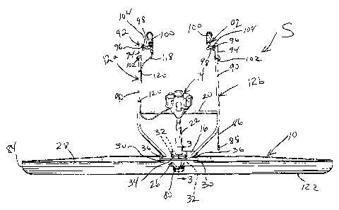
Une règle vibrante pour revêtements en béton comprend une lame de surfaçage, deux poignées montées sur ladite lame, un moteur, un mécanisme de production de vibrations, et une transmission reliant le moteur au mécanisme de production de vibrations, de sorte que lorsque le moteur est en marche il détermine la rotation de la transmission, cette transmission étant adaptée pour imposer un mouvement vibratoire à la lame. La transmission comprend un joint flexible à configuration inclinée permettant le montage du moteur vers l'arrière d'un bord d'attaque de la lame. Chaque poignée comprend un élément tubulaire allongé principal et une poignée, montés sur son extrémité proximale. La poignée comprend un premier élément tubulaire monté autour de l'élément tubulaire principal, un deuxième élément tubulaire s'étendant latéralement à partir du premier élément, et un troisième élément tubulaire s'étendant autour du deuxième élément, un élément de serrage étant monté sur le troisième élément. Le premier élément est en mesure d'assurer un mouvement rotatif et de translation relativement à l'élément tubulaire principal, et le troisième élément et l'élément de serrage étant en mesure d'assurer un déplacement rotatif relativement au deuxième élément. Des attaches sont prévues pour la fixation des premier et troisième éléments tubulaires à des emplacements sélectionnés relativement à l'élément tubulaire principal et du deuxième élément tubulaire respectivement.


Abrégé anglais

A vibrating screed for surfacing concrete comprises a surfacing blade, a pair of handle assemblies mounted to said blade, a motor, vibration causing mechanism and a transmission connecting the motor to the vibration causing mechanism such that, when the motor is in operation it causes the transmission to rotate with the transmission being adapted to impart a vibratory motion to the blade. The transmission includes a flexible joint having an angled configuration to allow the motor to be mounted rearwardly of a leading edge of the blade. Each handle assembly comprises a main elongated tubular member and a handle mounted at a proximal end thereof. The handle includes a first tubular element mounted around the main tubular member, a second tubular element extending sideways from the first element and a third tubular element extending around the second element, with a grip member being mounted to the third element. The first element is capable of relative rotatable and translational displacement with respect to the main tubular member, and the third element and grip member are capable of rotational displacement relative to the second element. Clamps are provided for securing the first and third tubular elements in selected positions relative to the main tubular member and to the second tubular element, respectively.

Revendications

Note : Les revendications sont présentées dans la langue officielle dans laquelle elles ont été soumises.


The embodiments of the invention in which an exclusive
property or privilege is claimed are defined as follows:
1. A vibrating device for surfacing concrete, comprising a
surfacing blade, steering means mounted to said blade, a
motor, vibration causing means and a transmission connecting
said motor to said vibration causing means, wherein when
said motor is in operation it causes said transmission to
rotate with said transmission imparting a vibratory motion
to said blade, said transmission comprising a flexible joint
having substantially straight first and second sections
having longitudinal axes angled to each other and
intersecting each other within said flexible joint.
2. A vibrating device as defined in claim 1, wherein said
first and second sections of said flexible joint comprise
upper and lower sections, said lower section of said
flexible joint extending substantially vertically above said
vibration causing means and said blade, whereas said upper
portion extends upwardly and rearwardly at an angle, said
transmission also comprising a drive shaft mounted between
said motor and said flexible joint, whereby said motor is
mounted rearwardly of a leading edge of said blade.
3. A vibrating device as defined in claim 2, wherein said
upper and lower sections of said flexible joint are integral
and are made of a resilient material at least where said
joint is flexible.
4. A vibrating device for surfacing concrete, comprising a
surfacing blade, steering means mounted to said blade, a
motor, vibration causing means and a transmission connecting
said motor to said vibration causing means, wherein when

said motor is in operation it causes said transmission to
rotate with said transmission imparting a vibratory motion
to said blade, said steering means comprising a main
elongated handle member and a handle mounted at a proximal
end thereof, said handle having a first element releasably
mounted to said main handle member for swiveling, when in an
unlocked position relative to said main handle member, at
least partly around a longitudinal axis of said main handle
member.
5. A vibrating device as defined in claim 4, wherein said
first element is slidably displaceable along said main
handle member.
6. A vibrating device for surfacing concrete, comprising a
surfacing blade, steering means mounted to said blade, a
motor, vibration causing means and a transmission connecting
said motor to said vibration causing means, wherein when
said motor is in operation it causes said transmission to
rotate with said transmission imparting a vibratory motion
to said blade, said steering means comprising a main
elongated handle member and a handle, said handle having a
first element mounted to a proximal end of said main handle
member, said handle having second and third elements
displaceable between locked and unlocked positions thereof,
wherein in said locked position said second and third
elements are rotatable relative to one another, whereas when
in said unlocked position, said second and third elements
are secured in a desired relative position, with a grip
member being mounted to said third element such that said
grip member may be swiveled at least partly around an axis
of said second element.

7. A vibrating device as defined in claim 6, wherein said
first element is releasably mounted to said main handle
member for swiveling, when in an unlocked position relative
to said main handle member, at least partly around an axis
of said main handle member.
8. A vibrating device as defined in claim 7, wherein said
first element is slidably displaceable along said main
handle member.
9. A vibrating device as defined in claim 6, wherein said
main handle member and said first element comprise
concentrically disposed tubular members, said second and
third elements comprising concentrically disposed tubular
members, said second element extending substantially at
right angles to said first element and said third element
extending substantially at right angles to said grip member
such that said grip member swivels in a plane substantially
parallel to said axis of said main handle member, locking
means being provided for retaining selected relative
positions between said main handle member and said first
element and between said second and third elements.
10. A vibrating device as defined in claim 1, wherein said
first and second sections of said flexible joint taper
towards each other.
11. A vibrating device as defined in claim 2, wherein said
upper and lower sections of said flexible joint taper
towards each other.
12. A vibrating device as defined in claim 3, wherein said
upper and lower sections of said flexible joint taper

towards each other.
13. A vibrating device as defined in claim 10, wherein said
first and second sections of said flexible joint are each
substantially frusto-conical shaped.
14. A vibrating device as defined in claim 11, wherein said
upper and lower sections of said flexible joint are each
substantially frusto-conical shaped.
15. A vibrating device as defined in claim 12, wherein said
upper and lower sections of said flexible joint are each
substantially frusto-conical shaped.
16. A vibrating device as defined in claim 1, wherein said
first and second sections of said flexible joint are made of
rubber.
17. A vibrating device as defined in claim 2, wherein said
upper and lower sections of said flexible joint are made of
rubber.
18. A vibrating device as defined in claim 3, wherein said
upper and lower sections of said flexible joint are made of
rubber.
19. A vibrating device as defined in claim 2, wherein said
upper section is threadably engaged to said drive shaft with
said lower section being keyed to said vibration causing
means.

Description

Note : Les descriptions sont présentées dans la langue officielle dans laquelle elles ont été soumises.


CA 02261508 1999-02-12
-1-
VIBRATING SCREED FOR SURFACING CONCRETE
BACKGROUND OF THE INVENTION
1. Field of the invention
s The present invention relates to devices for
surfacing concrete and, more particularly, to vibrating
screeds for concrete surfacing of the type having an
elongated blade mounted transversally at the bottom of a
pair of hand held handles with a motor being adapted to
~o transmit to the blade a vibratory movement.
2. Description of the Prior Art
Conventional vibrating screeds comprise, for
instance, an elongated blade extending horizontally and
transversally at lower ends of a pair of handles adapted to
15 be hand held and operated for displacing the screed over a
concrete surface. A motor is provided above the blade and
between the handles and has its shaft extending vertically
downwards from the motor to the blade and is connected
thereat such that, with a counterweight or a cam-like
2o arrangement, it imparts oscillatory movement to the blade
of high frequency but low amplitude.
The pair of handles permit an easy and constant
correction of the level of the concrete with minimum
effort. The blade may have different lengths, for example
2s between 4 and 12 feet . A throttle control of the motor is
provided at one of the handles such that the speed of the
motor may be monitored and adjusted as the blade is
displaced over the concrete being surfaced.
For instance, United States Patent No. 4,861,188
3o issued to Rouillard on August 29, 1989 discloses a method
and an apparatus for compacting and smoothing freshly
poured concrete during the construction of a floor or other
flat surface. The apparatus is a screed divided in two
portions. The first portion is used to level, compact and

CA 02261508 1999-02-12
-2-
remove excess concrete and the second portion allows the
screed to float on the freshly poured and soft concrete.
United States Patent No. 4,848,961 issued to Rouillard
on July 18, 1989 discloses a concrete screeding apparatus
and, more particularly, an improved portable and
lightweight vibrating concrete screed enabling a workman to
use same without the need for rigid forms. The screeding
apparatus comprises a generally elongated beam having a
horizontal surface and a generally vertical surface. A
~o plurality of vibrators are mounted on the beam. The height
of the vertical surface diminishes from the centre to the
edges so as to increase the amplitude of vibration and,
therefore, improve the manoeuvrability of the screed. In
addition, the corners formed by the trailing edge and the
~5 side edges of the horizontal surface are rounded so as to
avoid the penetration of the side edges into the freshly
poured concrete.
SUMMARY OF THE INVENTION
zo It is therefore an aim of the present invention
to provide an improved screed for surfacing concrete.
It is also an aim of the present invention to
provide such a concrete surfacing screed having adjustable
handles.
Therefore, in accordance with the present
invention, there is provided a vibrating device for
surfacing concrete, comprising a surfacing blade, handle
means mounted to said blade, a motor, vibration causing
3o means and transmission means connecting said motor to said
vibration causing means, wherein when said motor is in
operation it causes said transmission means to rotate with
said transmission mans being adapted to impart a vibratory
motion to said blade, said transmission means comprising a

CA 02261508 1999-02-12
-3-
flexible joint means having first and second sections
having longitudinal axes angled to each other.
Also in accordance with the present invention,
s there is provided a vibrating device for surfacing
concrete, comprising a surfacing blade, handle means
mounted to said blade, a motor, vibration causing means and
transmission means connecting said motor to said vibration
causing means, wherein when said motor is in operation it
~o causes said transmission means to rotate with said
transmission means being adapted to impart a vibratory
motion to said blade, said handle means comprising a main
elongated handle member and a handle mounted at a proximal
end thereof, said handle having a first element releasably
is mounted to said main handle member and being adapted to
swivel at least partly around an axis of said main handle
member.
Further in accordance with the present invention,
zo there is provided a vibrating device for surfacing
concrete, comprising a surfacing blade, handle means
mounted to said blade, a motor, vibration causing means and
transmission means connecting said motor to said vibration
causing means, wherein when said motor is in operation it
2s causes said transmission means to rotate with said
transmission mans being adapted to impart a vibratory
motion to said blade, said handle means comprising a main
elongated handle member and a handle, said handle having a
first element mounted to a proximal end of said main handle
3o member, said handle having second and third elements
capable of relative rotatable displacement and capable of
being secured in a desired relative position thereof with a
grip member being mounted to said third element such that
said grip member may be swiveled at least partly around an
35 axis of said second element.

CA 02261508 1999-02-12
-4-
BRIEF DESCRIPTION OF THE DRAWINGS
Having thus generally described the nature of the
present invention, reference will now be made to the
s accompanying drawings, showing by way of illustration a
preferred embodiment thereof and in which:
Fig. 1 is a front elevational view of a vibrating
screed in accordance with the present invention;
Fig. 2 is an enlarged perspective view of a
~o flexible joint or drive axle of the motor shaft of the
vibrating screed of Fig. 1;
Fig. 3 is a cross-sectional view taken along line
3-3 of Fig. 1; and
Fig. 4 is a front elevational view of an upper
15 ,part of the vibrating screed and showing one of the
adjustable handles thereof.
DESCRIPTION OF THE PREFERRED EMBODIMENTS
Fig. 1 illustrates a vibrating screed S in
zo accordance with the present invention and generally
comprising an elongated surfacing blade 10, a pair of
handle assemblies 12a and 12b extending upwardly and
rearwardly from the blade 10, and a motor 14 for imparting
vibratory movement to the blade 10 such that, when the
z5 blade 10 is displaced over a not yet set concrete surface,
it surfaces, i.e. smoothens, this concrete surface. The
motor 14 may be powered by gasoline or other fuels and may
also by electric.
More particularly, the handle assemblies 12a and
30 12b, which are spaced apart along the orientation of the
blade 10, are mounted at their lower ends to a plate 16
which defines a circular hole 18 (see Fig. 3) and are
further attached together by a cross bar 20. The motor 14
is mounted atop a shaft housing 2 within which extends a
35 drive shaft 24, as seen in Fig. 3. The drive shaft 24 is

CA 02261508 1999-02-12
-5-
rotatably driven by the motor 14 and is supported in the
shaft housing 22 by a pair of bearings and circlips (snap
rings) herein generally identified together at 25.
A housing weight 26, which is mounted to a rear
s vertical wall 28 of the blade 10 with nut and bolts (not
shown), is also secured at an upper surface thereof to the
plate 16 with a pair of elongated rubber or rubber-like
"vibro mounts" or cushions 30 extending between the plate
16 and the housing weight 26 such as to reduce a
~o transmission of the vibrations produced by the motor 14 at
the level of the blade 10 to the handle assemblies 12a and
12b. Bolts 32 secure the plate 16 to a lower enlarged end
34 of the shaft housing 22, the bolts 32 being tapped in
the enlarged end 34 and thus not being visible in Fig. 1
although their general locations have been identified in
broken lines in Fig. 1 for clarity of illustration
purposes. Headless bolts with pairs of nuts at their
opposed ends or standard nuts and bolts 36 extend through
the housing weight 26, the cushions 30 and the plate 16 to
zo secure these components together.
Now referring mainly to Fig. 3, the housing
weight 26 defines an upper cylindrical chamber 38, a lower
cylindrical chamber 40 which is shorter but of greater
diameter then the upper chamber 38, and a horizontal lower
z5 partition wall 42 between the upper and lower chambers 38
and 40, this lower partition wall 42 defining a circular
opening 44. An upper partition wall 46 extends horizontally
across an upper portion of the upper chamber and itself
defines a circular opening 48.
3o A flexible joint, coupling or drive axle 50 which
is shown in detail in Fig. 2 includes an integral resilient
hard rubber main body 52 having opposed frusto-conical
upper and lower sections 54 and 56, respectively, upper and
lower metal discs or washers 58 and 60, respectively, and
35 upper bolt 62 and a lower hexagonal, i.e. Allen key-like,

CA 02261508 1999-02-12
-6-
pin 64. As seen in Fig. 3, a head 66 of the bolt 62 is
embedded in the upper section 52 of the main body 52 of the
drive axle 50 and extends outwardly therefrom through the
upper washer 58 such that a threaded stem 68 of the bolt 62
s is threadably engaged to the drive shaft 24. The head 66 of
the bolt 62 is welded to the upper washer 58.
The hexagonal pin 64 is fixed by welding at its
upper end 70 to the lower washer 60 with the lower washer
60 being fixed to the lower section 56 of the main body 52
~o of the drive axle 50 such that the hexagonal pin 64 extends
through the lower washer 60 and into a mating hexagonal
aperture defined in an upper end 72 of a shaft assembly 74
which extends in the upper and lower chambers 38 and 40,
respectively. This upper end 72 extends through and is
~S journaled in the upper opening 48 defined in the upper
partition wall 46. A lower end 76 of the shaft assembly 74
extends through and is journaled in the lower opening 44
defined in the lower partition wall 42. A counter weight 78
is eccentrically mounted in the lower chamber 40 to the
20 lower end 76 of the shaft assembly 74.
A cover 80 is mounted exteriorly around a wall 82
of the housing weight 26 and transversally therebelow for
closing the lower end of the housing weight 26. The cover
80 includes a rubber seal 81 to ensure a seal at the lower
z5 end of the wall 82 and an aluminum disc 83 extending
inwardly of the seal 81. The cover 80 prevents dirt and
other foreign matters from accessing the lower chamber 40
and possibly damaging the rotating vibration causing
counterweight 78 and a transmission mechanism which links
3o the motor 14 to the counterweight 78 and which generally
includes the drive shaft 24, the flexible drive axle 50 and
the shaft assembly 74.
Accordingly, when in operation, the motor 14
causes the rotation of the drive shaft 24 which itself
35 causes the drive axle 50 to rotate as being fixedly secured

CA 02261508 1999-02-12
_7_
thereto by the bolt 62. The drive axle 50 in turn rotatably
drives the shaft assembly 74 by way of the hexagonal pin 64
with the shaft assembly 74 causing a rotation of the
counter weight 78 which, due to its eccentricity, imparts
s vibration to the housing weight 26 and thus to the blade 10
mounted thereto. The cushions 30 again reduce the amount of
vibrations transmitted to the handle assemblies 12a and
12b.
The lower section 56 of the drive axle 50 extends
~o substantially vertically, whereas the upper section 54
thereof extends upwardly and rearwardly and coaxially with
the drive shaft 24 which is angled approximately at 22°
with respect to the vertical. This configuration allows for
the motor 14 to be rearwardly offset from the blade 10 such
as not to interfere with obstacles, such as walls and the
like, when the blade 10 of the vibrating screed S is
displaced near, along or around such obstacles. Also, the
drive axle 50 and the ensuing angle of the drive shaft 24
results in that the motor 14 is positioned over a cutting
zo portion 84 of the blade 10 which is beneficial to the
handling and performance of the vibrating screed S and
provides an overall balance therein.
As seen in Fig. 1, the vibrating screed S is
provided with a support stand 86 which is pivotally mounted
z5 at its upper end to the handle assembly 12b. The support
stand 86 is herein shown in its collapsed, or storage,
position along the handle assembly 12b, and is retained in
this position by a releasable clip (not shown). Once
released from this clip, the support stand may be pivoted
3o away from the handle assembly 12b and a rubber foot 88
thereof may then engage the ground such as to support the
vibrating screed S in a position similar to that shown in
Fig. 1.
Now referring to Fig. 1 and mainly to Fig. 4,
35 each handle assembly 12a and 12b is provided with an

CA 02261508 1999-02-12
_g_
elongated main tubular member 90 which is elbowed at its
lower third so as to be directed inwardly towards and up to
the plate 16, and is also provided with an adjustable
handle 92. The handle 92 includes a first tubular element
s 94 slidably mounted over the tubular member 90, a second
tubular element 96 fixedly mounted to the first tubular
element 94 and extending at right angles thereto, a third
tubular element 98 slidably mounted over the second tubular
element 96, and a textured rubber grip member 100 fixedly
~o mounted to the third tubular element 98 and extending at
right angles thereto. First and second releasable clamps
102 and 104, respectively, are provided around the first
and third tubular elements 94 and 98, respectively.
The first and third tubular elements 94 and 98
define notches or slots 106 in their respective walls in
order to allow them to compress respectively onto the
tubular member 90 and the second tubular element 96 when
the jaws of the clamps 102 and 104 are brought closer
together using nuts 108 which define Allen key type
zo recesses. When the first clamp 102 is loose, the first
tubular element 94 may be displaced translationally along
the tubular member 90 (see arrows 110) and may also be
rotated with respect thereto as per arrows 112 such that
whole handle 92 may be swiveled around the tubular member
z5 90 until a user's preferential position, whereat the nut
108 of the first clamp 104 is rotated clockwise such as to
cause the jaws of the clamp 104 to tightly bring the
slotted portion of first tubular element 94 in secure
frictional engagement with the tubular member 90.
3o Similarly, when the second clamp 104 is loose,
the third tubular element 98 may be rotated around the
tubular member 90 (see arrows 114) such as to adjust the
angular position of the grip member 100 with respect to the
tubular member 90 as per a user's preferential position,
3s whereat the nut 108 of the second clamp 104 is rotated

CA 02261508 1999-02-12
_g_
clockwise such as to cause the jaws of the clamp 104 to
tightly bring the slotted portion of third tubular element
98 in secure frictional engagement with the second tubular
element 96.
s The handle 92 of one of the handle assemblies 12a
and 12b is provided with a throttle control 116 connected
to a throttle cable 118 extending to the motor 14. tie
wraps 120 are used to attach the cable 118 to the tubular
member 90 of this handle assembly (i.e. handle assembly 12a
~o in Fig. 1). The blade 10 has a leading edge 122.

Dessin représentatif
Une figure unique qui représente un dessin illustrant l'invention.
États administratifs

2024-08-01 : Dans le cadre de la transition vers les Brevets de nouvelle génération (BNG), la base de données sur les brevets canadiens (BDBC) contient désormais un Historique d'événement plus détaillé, qui reproduit le Journal des événements de notre nouvelle solution interne.

Veuillez noter que les événements débutant par « Inactive : » se réfèrent à des événements qui ne sont plus utilisés dans notre nouvelle solution interne.

Pour une meilleure compréhension de l'état de la demande ou brevet qui figure sur cette page, la rubrique Mise en garde , et les descriptions de Brevet , Historique d'événement , Taxes périodiques et Historique des paiements devraient être consultées.

Historique d'événement

Description Date
Inactive : Périmé (brevet - nouvelle loi) 2019-02-12
Demande visant la révocation de la nomination d'un agent 2018-09-14
Demande visant la nomination d'un agent 2018-09-14
Inactive : Regroupement d'agents 2018-09-01
Demande visant la nomination d'un agent 2018-08-30
Inactive : Regroupement d'agents 2018-08-30
Demande visant la révocation de la nomination d'un agent 2018-08-30
Lettre envoyée 2012-05-15
Lettre envoyée 2010-06-17
Inactive : Correspondance - Transfert 2010-04-16
Inactive : Lettre officielle 2010-03-30
Inactive : Transfert individuel 2010-03-04
Inactive : Lettre officielle 2007-04-24
Lettre envoyée 2007-04-12
Inactive : Lettre officielle 2007-02-22
Lettre envoyée 2007-02-22
Inactive : Transferts multiples 2007-02-12
Inactive : Transferts multiples 2007-01-09
Inactive : Lettre officielle 2006-11-28
Inactive : Paiement correctif - art.78.6 Loi 2006-11-20
Inactive : CIB de MCD 2006-03-12
Inactive : TME en retard traitée 2005-04-08
Lettre envoyée 2005-02-14
Inactive : Grandeur de l'entité changée 2004-03-03
Accordé par délivrance 2002-06-11
Inactive : Page couverture publiée 2002-06-10
Lettre envoyée 2002-04-09
Inactive : Demande ad hoc documentée 2002-03-21
Inactive : Grandeur de l'entité changée 2002-03-19
Inactive : Lettre officielle 2002-03-19
Inactive : Supprimer l'abandon 2002-03-19
Inactive : Correspondance - Poursuite 2002-03-04
Inactive : Supprimer l'abandon 2002-02-27
Inactive : Lettre officielle 2002-02-25
Inactive : Correspondance - Poursuite 2002-02-14
Réputée abandonnée - omission de répondre à un avis sur les taxes pour le maintien en état 2002-02-12
Préoctroi 2002-01-28
Inactive : Taxe finale reçue 2002-01-28
Lettre envoyée 2001-12-13
Un avis d'acceptation est envoyé 2001-12-13
Inactive : Approuvée aux fins d'acceptation (AFA) 2001-12-01
Avancement de l'examen jugé conforme - alinéa 84(1)a) des Règles sur les brevets 2001-11-22
Lettre envoyée 2001-11-22
Inactive : Grandeur de l'entité changée 2001-11-22
Exigences relatives à la révocation de la nomination d'un agent - jugée conforme 2001-11-20
Inactive : Lettre officielle 2001-11-20
Exigences relatives à la nomination d'un agent - jugée conforme 2001-11-20
Inactive : Avancement d'examen (OS) 2001-11-08
Exigences pour une requête d'examen - jugée conforme 2001-11-08
Toutes les exigences pour l'examen - jugée conforme 2001-11-08
Inactive : Taxe de devanc. d'examen (OS) traitée 2001-11-08
Requête d'examen reçue 2001-11-08
Modification reçue - modification volontaire 2001-10-22
Demande visant la révocation de la nomination d'un agent 2001-10-22
Demande visant la nomination d'un agent 2001-10-22
Réputée abandonnée - omission de répondre à un avis sur les taxes pour le maintien en état 2001-02-12
Demande publiée (accessible au public) 2000-08-12
Inactive : Page couverture publiée 2000-08-11
Lettre envoyée 1999-11-12
Inactive : Transfert individuel 1999-10-18
Inactive : CIB attribuée 1999-03-31
Symbole de classement modifié 1999-03-31
Inactive : CIB attribuée 1999-03-31
Inactive : CIB en 1re position 1999-03-31
Inactive : Lettre de courtoisie - Preuve 1999-03-16
Inactive : Certificat de dépôt - Sans RE (Anglais) 1999-03-11
Demande reçue - nationale ordinaire 1999-03-11

Historique d'abandonnement

Date d'abandonnement Raison Date de rétablissement
2002-02-12
2001-02-12

Taxes périodiques

Le dernier paiement a été reçu le 2002-02-01

Avis : Si le paiement en totalité n'a pas été reçu au plus tard à la date indiquée, une taxe supplémentaire peut être imposée, soit une des taxes suivantes :

  • taxe de rétablissement ;
  • taxe pour paiement en souffrance ; ou
  • taxe additionnelle pour le renversement d'une péremption réputée.

Les taxes sur les brevets sont ajustées au 1er janvier de chaque année. Les montants ci-dessus sont les montants actuels s'ils sont reçus au plus tard le 31 décembre de l'année en cours.
Veuillez vous référer à la page web des taxes sur les brevets de l'OPIC pour voir tous les montants actuels des taxes.

Titulaires au dossier

Les titulaires actuels et antérieures au dossier sont affichés en ordre alphabétique.

Titulaires actuels au dossier
2544-9455 QUEBEC INC.
Titulaires antérieures au dossier
ROGER ROUILLARD
Les propriétaires antérieurs qui ne figurent pas dans la liste des « Propriétaires au dossier » apparaîtront dans d'autres documents au dossier.
Documents

Pour visionner les fichiers sélectionnés, entrer le code reCAPTCHA :


Pour visualiser une image, cliquer sur un lien dans la colonne description du document. Pour télécharger l'image (les images), cliquer l'une ou plusieurs cases à cocher dans la première colonne et ensuite cliquer sur le bouton "Télécharger sélection en format PDF (archive Zip)" ou le bouton "Télécharger sélection (en un fichier PDF fusionné)".

Liste des documents de brevet publiés et non publiés sur la BDBC .

Si vous avez des difficultés à accéder au contenu, veuillez communiquer avec le Centre de services à la clientèle au 1-866-997-1936, ou envoyer un courriel au Centre de service à la clientèle de l'OPIC.


Description du
Document 
Date
(aaaa-mm-jj) 
Nombre de pages   Taille de l'image (Ko) 
Abrégé 1999-02-11 1 38
Description 1999-02-11 9 388
Revendications 1999-02-11 3 109
Dessins 1999-02-11 4 110
Revendications 2001-10-21 4 138
Dessin représentatif 2002-05-08 1 14
Dessin représentatif 2000-08-08 1 11
Certificat de dépôt (anglais) 1999-03-10 1 165
Courtoisie - Certificat d'enregistrement (document(s) connexe(s)) 1999-11-11 1 115
Rappel de taxe de maintien due 2000-10-15 1 110
Accusé de réception de la requête d'examen 2001-11-21 1 179
Avis du commissaire - Demande jugée acceptable 2001-12-12 1 166
Avis concernant la taxe de maintien 2005-04-10 1 172
Quittance d'un paiement en retard 2005-04-20 1 165
Courtoisie - Certificat d'enregistrement (document(s) connexe(s)) 2012-05-14 1 104
Taxes 2003-01-06 1 41
Correspondance 2001-10-21 3 68
Correspondance 2001-11-19 1 17
Correspondance 2001-11-19 1 14
Correspondance 2002-01-27 1 29
Correspondance 2002-02-03 1 19
Correspondance 2001-08-10 2 13
Correspondance 2002-03-03 2 51
Correspondance 2002-04-08 1 11
Correspondance 1999-03-15 1 32
Correspondance 1999-10-17 2 89
Taxes 2002-01-31 2 76
Taxes 2004-02-11 1 34
Taxes 2005-04-07 1 36
Taxes 2006-01-16 1 52
Correspondance 2006-11-27 1 15
Taxes 2006-12-20 1 45
Correspondance 2007-02-21 1 12
Correspondance 2007-04-23 1 12
Taxes 2008-01-20 1 47
Taxes 2008-12-30 1 46
Correspondance 2010-03-29 1 15
Correspondance 2010-06-16 1 13
Correspondance 2010-06-29 3 96