Sélection de la langue

Search

Sommaire du brevet 2265081 

Énoncé de désistement de responsabilité concernant l'information provenant de tiers

Une partie des informations de ce site Web a été fournie par des sources externes. Le gouvernement du Canada n'assume aucune responsabilité concernant la précision, l'actualité ou la fiabilité des informations fournies par les sources externes. Les utilisateurs qui désirent employer cette information devraient consulter directement la source des informations. Le contenu fourni par les sources externes n'est pas assujetti aux exigences sur les langues officielles, la protection des renseignements personnels et l'accessibilité.

Disponibilité de l'Abrégé et des Revendications

L'apparition de différences dans le texte et l'image des Revendications et de l'Abrégé dépend du moment auquel le document est publié. Les textes des Revendications et de l'Abrégé sont affichés :

  • lorsque la demande peut être examinée par le public;
  • lorsque le brevet est émis (délivrance).
(12) Brevet: (11) CA 2265081
(54) Titre français: SUPPORT DE RESSORT DE SUSPENSION POUR COMPRESSEUR HERMETIQUE
(54) Titre anglais: SUSPENSION SPRING SUPPORT FOR HERMETIC COMPRESSORS
Statut: Périmé et au-delà du délai pour l’annulation
Données bibliographiques
(51) Classification internationale des brevets (CIB):
  • F04B 19/22 (2006.01)
  • F04B 53/16 (2006.01)
  • F04C 29/00 (2006.01)
  • F16F 15/06 (2006.01)
(72) Inventeurs :
  • CALCIOLARI, LEONELO ANTONIO (Brésil)
  • SILVA, JOSE MARIO (Brésil)
(73) Titulaires :
  • TECUMSEH PRODUCTS COMPANY
(71) Demandeurs :
  • TECUMSEH PRODUCTS COMPANY (Etats-Unis d'Amérique)
(74) Agent: MARKS & CLERK
(74) Co-agent:
(45) Délivré: 2002-12-31
(22) Date de dépôt: 1999-03-09
(41) Mise à la disponibilité du public: 1999-09-11
Requête d'examen: 1999-03-09
Licence disponible: S.O.
Cédé au domaine public: S.O.
(25) Langue des documents déposés: Anglais

Traité de coopération en matière de brevets (PCT): Non

(30) Données de priorité de la demande:
Numéro de la demande Pays / territoire Date
MU7800634-1 (Brésil) 1998-03-11

Abrégés

Abrégé anglais


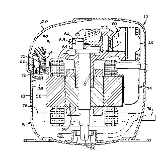
A hermetic compressor assembly and method of assembling a hermetic
compressor. The assembly includes a housing, a compression mechanism, an
electric
motor in driving communication with the compression mechanism, a plurality of
suspension spring supports, and a suspension spring for each. The motor and
compression mechanism comprise a subassembly that is installed in the housing.
The
support has first and second portions and a border between the portions. The
first
support portion is attached to the housing. The second support portion has an
arcuate
opening at the border between the portions, such that the second portion can
be bent
inwardly at this border. The suspension spring extends between the support
second
portion and the subassembly. The method includes the steps of attaching the
first
support portion to the interior of the housing, installing the subassembly
into the
housing past the spring supports, bending the support between its first and
second
portions in a radially inward direction, attaching the spring to the second
spring
portion, attaching the spring to the subassembly, whereby the subassembly is
at least
partially supported within the housing by the support through the spring.

Revendications

Note : Les revendications sont présentées dans la langue officielle dans laquelle elles ont été soumises.


WHAT IS CLAIMED IS:
1. A hermetic compressor assembly comprising:
a housing;
a compression mechanism;
an electric motor in driving communication with said compression
mechanism, said motor and said compression mechanism comprising a subassembly,
said subassembly installed in said housing;
a plurality of spring supports of single-piece construction, said support
having first and second portions and a border between said portions, said
first portion
attached to said housing, said second portion having an arcuate opening at
said border,
such that said second portion can be bent inwardly at said border; and
a suspension spring attached to each said spring support extending
between the respective said support second portion and said subassembly and
being
attached to said subassembly.
2. The hermetic compressor assembly of Claim 1, wherein said support is
arcuate in a transverse direction.
3. The hermetic compressor assembly of Claim 1, wherein said first
portion of said support includes a trapezoidal section and a rectangular
section, said
trapezoidal section includes a narrow end bordering said second section and a
wide end
bordering said rectangular section.
4. The hermetic compressor assembly of Claim 3, wherein said
rectangular section includes an edge opposite said trapezoidal section, said
edge having
a pair of wide polygonal cuts defining two lateral and trapezoidal end points
and an
orthogonally bent forward intermediary tongue.
5. The hermetic compressor assembly of Claim 1, wherein said second
portion includes a centrally and longitudinally located large circular orifice
for
engaging said springs, and said arcuate opening is between said orifice and
said border.
6. The hermetic compressor assembly of Claim 1, wherein said first
portion of said support includes a pair of projecting contact portions.
7

7. The hermetic compressor assembly of Claim 1, wherein said
compression mechanism is a reciprocating piston compressor.
8. A method for assembling a hermetic compressor, comprising the steps
of:
providing a housing, a compression mechanism and electric motor
subassembly, a plurality of spring supports having first and second portions,
and a
plurality of suspension springs;
attaching the first portion of each support to the housing;
installing the subassembly into the housing past the spring supports;
then bending the supports between their first and second portions in a
radially inward direction;
attaching the springs to the respective second support portions; and
then attaching the springs to the subassembly;
whereby the subassembly is supported within the housing by the
supports through the springs.
9. The method of Claim 8, wherein said step of attaching the springs to the
second support portions precedes said bending step.
8

Description

Note : Les descriptions sont présentées dans la langue officielle dans laquelle elles ont été soumises.

10152025CA 02265081 1999-03-09Leonelo Antonio CalciolariJosé Mario SilvaSUSPENSION SPRING SUPPORTF R HERMETIC COMPRESSORSThe present invention relates to hermetic compressors, particularlyreciprocating piston hermetic compressors, and methods for their assembly.Reciprocating piston hermetic compressors presently known and widelyutilized typically have their motor and compression mechanism subassembliessuspended or supported within their housings by a plurality of springs. Suspensionsprings for such compressors are attached between supports distributed about andconnected to the interior of the housing and portions of the motor and compressionmechanism subassembly, such as the frame thereof.With reference to the above presently existing and utilized supports for suchsuspension springs, previous compressors often require the use of a spring supporthaving two parts in order to facilitate easy and convenient assembly of the compressor.On the other hand, there presently exist hermetic compressor units in whicheach suspension spring support consists of only one part, but which require additionalradial space between the interior of the housing and the compressor subassembly framein order to accommodate easy and convenient assembly of the compressor. This isbecause the respective supports are already bent into their configuration before beingattached to the interior of the housing before installation of the motor and compressionmechanism subassembly thereinto.SUMMARY OF THE INVENTIONThe suspension spring support of the present invention and the inventivemethod of assembling such compressors overcome the above-mentioned drawbacks.The inventive support is able to combine, under conditions of extraordinaryequilibrium, the positive characteristics of both types of known supports but is notaffected by their respective drawbacks.In other words, the suspension spring support of the present invention is madeas a whole, single part for each suspension spring, but does not require eitheradditional radial space between the interior of the housing and the motor and1015202530CA 02265081 1999-03-09compression mechanism subassembly, or any movement of the compressor assemblyat the place and time of installation of the motor and compression mechanismsubassembly.The inventive spring support referred to, therefore, is essentially made of asingle stamped part that, during its stamping is not completely bent into its specific anddefinitive configuration, this being done only at the time of the installation of themotor and compression mechanism subassembly into the housing, its finalconfiguration being obtained with the use of manual or automatic tools, as thecompressor assembly moves on the production line.The present invention provides a hermetic compressor assembly including ahousing, a compression mechanism, an electric motor in driving communication withthe compression mechanism, the motor and compression mechanism comprising asubassembly installed in said housing, and a plurality of spring supports of single-piece construction and having first and second portions and a border therebetween.The first portion is attached to said housing and the second portion has an arcuateopening at the border, such that the second portion can be bent inwardly at the border.A suspension spring is attached to each spring support and extends between therespective support second portion and the subassembly and is attached to thesubassembly.The present invention also provides a method for assembling a hermeticcompressor and has the steps of: providing a housing, a compression mechanism andelectric motor subassembly, a plurality of spring supports having first and secondportions, and a plurality of suspension springs; attaching the first portion of eachsupport to the housing; installing the subassembly into the housing past the springsupports; then bending the supports between their first and second portions in aradially inward direction; attaching the springs to the respective second supportportions; and then attaching the springs to the subassembly. The subassembly is thussupported within the housing by the supports through the springs.BRIEE DESQRIPTION OF THE DRAWINGSThe above—mentioned and other features and objects of this invention, and themanner of attaining them, will become more apparent and the invention itself will be1015202530CA 02265081 1999-03-09better understood by reference to the following description of the embodiments of theinvention taken in conjunction with the accompanying drawings, wherein:Figure 1 is a sectional side view of a hermetic compressor embodying thepresent invention;Figure 2 is an enlarged, fragmentary sectional side view of the presentinvention shown in Figure 1;Figure 3A is a frontal View of the suspension spring support shown as obtainedby its final stamping operation;Figure 3B is a profile view of the suspension spring support shown inFigure 3A;Figure 3C is a longitudinal central section view, along 3C-3C in Figure 3A;Figure 4 is a frontal view of the suspension spring support blank shown prior toits final stamping operation;Figure 5 repeats the section view in Figure 3C, but with the spring support inits final definitive bent configuration as obtained during the assembling of thecompressor assembly with its suspension spring; andFigure 6 is a side view of the suspension spring.DETAILED DESQRIPTION QF THE INVENTIONThe hermetic compressor assembly described herein is commonly use inrefrigeration systems. Referring first to Figures 1 and 2, hermetic compressorassembly 10 includes compression mechanism 12, which in the depicted embodimentis a reciprocating piston type, electric motor 14, housing 16, suspension spring support22, and suspension spring 46. Compression mechanism 12 includes cylinder 60,piston 62, and connecting rod 64. Electric motor 14 includes rotor 5 6, stator 58,crankshaft 66 and frame 68. Frame 68 has tapped holes 70 in frame extension 72 fortl1readedly receiving a plurality of springs 46 as discussed fiirther hereinbelow.Compression mechanism 12 and motor 14 in combination form subassembly 48.Housing 16 comprises lower portion 18 and cover 20, each of which may be made insteel. Electrical power supplied to motor 14 through stator 58 drives the rotation ofrotor 56 and crankshaft 66 coupled to rotor 56. Eccentric portion 63 of crankshaft 66drives piston 62 through connecting rod 64. Suction tube 74 passes through lower1015202530CA 02265081 1999-03-09housing portion 18, delivering refrigerant into compressor assembly 10. Therefrigerant flows into cylinder 60 and is compressed by piston 62. The high pressurerefrigerant then exits the compressor assembly through a discharge tube (not shown).Oil 76 for lubrication of compressor assembly 10 is disposed in lower housingportion 18.A plurality of suspension spring supports 22, at least three, are attached tolower portion 18 by any suitable means, such as means of resistance welding and aredistributed about the cylindrical interior surface of lower portion 18 approximatelyequal distance from one another. Spring 46 extends between support 22 and tappedhole 70 in frame extension 72 of subassembly 48. Intermediary tongue 38 of support22 provides a stop for frame extension 72 to protect the tip of crankshaft 66 fromcontacting lower housing portion 18.As shown in Figures 3A - 3C, the suspension spring support 22 consists of asingle unit, entirely stamped from sheet steel, with a surface slightly arched intransverse direction. Support 22 contains first portion 25 and second portion 27. Firstportion 25 includes narrow section 26. Second portion 27 includes large middlesection 24 and lower section 32. Middle section 24 is substantially of trapezoidalshape, and extending from its smaller base is substantially plane, rectangular andnarrow section 26 with a free edge made up of two symmetrically inclined andconvergent portions 28 that are interconnected by arched end portion 30. Middlesection 24, from its wider base, extends over large lower section 32. Lower section 32is basically rectangular in shape, but with large polygonal and symmetrical cuts 45 inborder 34 forming two lateral and trapezoidal end points 36, as well as a wideintermediary tongue 38, slightly trapezoidal, with two inclined planes and orthogonallybent forward. End points 36 include projecting contact portions 54 for resistantwelding support 22 to the interior surface of lower housing portion 18.Furthermore, narrow section 26 has centrally and longitudinally located largecircular orifice 40 with salient ring border 42 and large transverse aperture 44 in theshape of a quarter moon directly adjacent orifice 40. Aperture 44 is placed very nearthe separation line between end section 26 and middle section 24.1015202530CA 02265081 1999-03-09The single and whole support part for the suspension spring, presented here, isobtained from the final stamping operation as described above and illustrated inFigures 3A through 3C. Figure 4 shows support 22 as a blank prior to its finalstamping operation.Spring 46, as shown in Figure 6, has three portions 50, 51, 52. First portion 50and third portion 52 include a plurality of coils having substantially uniform diameters.The diameter of first portion 50 is greater than the diameter of third portion 52.Second portion 51 includes a plurality of coils of varying diameters such that portion51 is generally tapered between the diameter of first portion 50 and the diameter ofthird portion 52. The diameter of orifice 40 is smaller than the diameter of first portion50 and greater than the diameter of third portion 52 and the largest diameter of portion51. Second portion 51 and third portion 52 of spring 46 are disposed through orifice40 until first portion 50 abuts with the perimeter of orifice 40 as shown in Figure 5.Third portion 52 of spring 46 in Figure 2 is threadedly received in tapped hole 70provided in frame extension 72 of subassembly 48.Assembly of the compressor on the production line includes the followingsteps. Lower housing portion 18 with a plurality of unbent supports 22 as shown inFigs. 3A-3C attached thereto is received by an assembler. The assembler insertscompression mechanism and motor subassembly 48 into lower housing portion 18,aligning frame extensions 72 with supports 22. Next the assembler bends supports 22into their final configuration, as shown in Figure 5, with a manual or automatic tool.The definitive, final configuration is imparted to support 22 by bending narrow section26 forward, which is made possible and facilitated by the presence of the quarter-moonshaped transverse aperture 44, giving section 26 a slightly inclined and ascendingorientation. Springs 22 are disposedpthrough each orifice 40 of supports 22 andthreadedly attached to tapped holes 70 provided in frame extensions 72. Subassembly48 is thus suspended from supports 22 through spring 46. Cover 20 is then attached tolower housing portion 18. Notably, suspension spring 46 may be positioned in thelarge circular orifice 40 either before or after the bending operation.While this invention has been described as having different embodiments, thepresent invention can be further modified within the spirit of the scope of thisCA 02265081 1999-03-09disclosure. This application is therefore intended to cover any variations, uses, oradaptations of the invention using its general principles. Further, this application isintended to cover such departures from the present disclosure as come within known orcustomary practice in the art to which this invention pertains and which fall within thelimits of the appended claims.
Dessin représentatif
Une figure unique qui représente un dessin illustrant l'invention.
États administratifs

2024-08-01 : Dans le cadre de la transition vers les Brevets de nouvelle génération (BNG), la base de données sur les brevets canadiens (BDBC) contient désormais un Historique d'événement plus détaillé, qui reproduit le Journal des événements de notre nouvelle solution interne.

Veuillez noter que les événements débutant par « Inactive : » se réfèrent à des événements qui ne sont plus utilisés dans notre nouvelle solution interne.

Pour une meilleure compréhension de l'état de la demande ou brevet qui figure sur cette page, la rubrique Mise en garde , et les descriptions de Brevet , Historique d'événement , Taxes périodiques et Historique des paiements devraient être consultées.

Historique d'événement

Description Date
Lettre envoyée 2006-08-10
Inactive : Lettre officielle 2006-06-21
Inactive : Transferts multiples 2006-05-11
Inactive : CIB de MCD 2006-03-12
Le délai pour l'annulation est expiré 2006-03-09
Lettre envoyée 2005-03-09
Inactive : TME en retard traitée 2003-06-19
Lettre envoyée 2003-03-10
Accordé par délivrance 2002-12-31
Inactive : Page couverture publiée 2002-12-30
Inactive : Taxe finale reçue 2002-10-17
Préoctroi 2002-10-17
Un avis d'acceptation est envoyé 2002-05-30
Lettre envoyée 2002-05-30
Un avis d'acceptation est envoyé 2002-05-30
Inactive : Approuvée aux fins d'acceptation (AFA) 2002-05-16
Lettre envoyée 2000-04-06
Inactive : Correspondance - Transfert 2000-03-22
Inactive : Transfert individuel 2000-03-09
Inactive : Certificat de dépôt - RE (Anglais) 1999-10-06
Demande de priorité reçue 1999-09-13
Demande publiée (accessible au public) 1999-09-11
Inactive : Page couverture publiée 1999-09-10
Modification reçue - modification volontaire 1999-05-10
Inactive : CIB attribuée 1999-05-05
Inactive : CIB en 1re position 1999-05-05
Inactive : Lettre de courtoisie - Preuve 1999-04-20
Inactive : Certificat de dépôt - RE (Anglais) 1999-04-14
Demande reçue - nationale ordinaire 1999-04-13
Exigences pour une requête d'examen - jugée conforme 1999-03-09
Toutes les exigences pour l'examen - jugée conforme 1999-03-09

Historique d'abandonnement

Il n'y a pas d'historique d'abandonnement

Taxes périodiques

Le dernier paiement a été reçu le 2002-02-28

Avis : Si le paiement en totalité n'a pas été reçu au plus tard à la date indiquée, une taxe supplémentaire peut être imposée, soit une des taxes suivantes :

  • taxe de rétablissement ;
  • taxe pour paiement en souffrance ; ou
  • taxe additionnelle pour le renversement d'une péremption réputée.

Les taxes sur les brevets sont ajustées au 1er janvier de chaque année. Les montants ci-dessus sont les montants actuels s'ils sont reçus au plus tard le 31 décembre de l'année en cours.
Veuillez vous référer à la page web des taxes sur les brevets de l'OPIC pour voir tous les montants actuels des taxes.

Historique des taxes

Type de taxes Anniversaire Échéance Date payée
Enregistrement d'un document 1999-03-09
Taxe pour le dépôt - générale 1999-03-09
Requête d'examen - générale 1999-03-09
Enregistrement d'un document 2000-03-09
TM (demande, 2e anniv.) - générale 02 2001-03-09 2001-02-06
TM (demande, 3e anniv.) - générale 03 2002-03-11 2002-02-28
Taxe finale - générale 2002-10-17
TM (brevet, 4e anniv.) - générale 2003-03-10 2003-06-19
Annulation de la péremption réputée 2003-03-10 2003-06-19
TM (brevet, 5e anniv.) - générale 2004-03-09 2003-12-31
Titulaires au dossier

Les titulaires actuels et antérieures au dossier sont affichés en ordre alphabétique.

Titulaires actuels au dossier
TECUMSEH PRODUCTS COMPANY
Titulaires antérieures au dossier
JOSE MARIO SILVA
LEONELO ANTONIO CALCIOLARI
Les propriétaires antérieurs qui ne figurent pas dans la liste des « Propriétaires au dossier » apparaîtront dans d'autres documents au dossier.
Documents

Pour visionner les fichiers sélectionnés, entrer le code reCAPTCHA :


Pour visualiser une image, cliquer sur un lien dans la colonne description du document. Pour télécharger l'image (les images), cliquer l'une ou plusieurs cases à cocher dans la première colonne et ensuite cliquer sur le bouton "Télécharger sélection en format PDF (archive Zip)" ou le bouton "Télécharger sélection (en un fichier PDF fusionné)".

Liste des documents de brevet publiés et non publiés sur la BDBC .

Si vous avez des difficultés à accéder au contenu, veuillez communiquer avec le Centre de services à la clientèle au 1-866-997-1936, ou envoyer un courriel au Centre de service à la clientèle de l'OPIC.


Description du
Document 
Date
(aaaa-mm-jj) 
Nombre de pages   Taille de l'image (Ko) 
Abrégé 1999-03-08 1 32
Description 1999-03-08 6 290
Revendications 1999-03-08 2 69
Dessins 1999-03-08 2 76
Dessins 1999-05-09 2 82
Dessin représentatif 1999-09-01 1 23
Certificat de dépôt (anglais) 1999-04-13 1 165
Certificat de dépôt (anglais) 1999-10-05 1 164
Demande de preuve ou de transfert manquant 2000-03-12 1 109
Courtoisie - Certificat d'enregistrement (document(s) connexe(s)) 2000-04-05 1 113
Rappel de taxe de maintien due 2000-11-13 1 112
Avis du commissaire - Demande jugée acceptable 2002-05-29 1 165
Avis concernant la taxe de maintien 2003-04-06 1 174
Quittance d'un paiement en retard 2003-07-10 1 165
Avis concernant la taxe de maintien 2005-05-03 1 172
Taxes 2003-06-18 1 60
Taxes 2002-02-27 1 65
Correspondance 1999-04-19 1 31
Correspondance 2002-10-16 1 50
Correspondance 1999-09-12 2 74
Taxes 2001-02-05 1 49
Correspondance 2006-06-20 1 23
Correspondance 2006-08-09 1 10