Sélection de la langue

Search

Sommaire du brevet 2266187 

Énoncé de désistement de responsabilité concernant l'information provenant de tiers

Une partie des informations de ce site Web a été fournie par des sources externes. Le gouvernement du Canada n'assume aucune responsabilité concernant la précision, l'actualité ou la fiabilité des informations fournies par les sources externes. Les utilisateurs qui désirent employer cette information devraient consulter directement la source des informations. Le contenu fourni par les sources externes n'est pas assujetti aux exigences sur les langues officielles, la protection des renseignements personnels et l'accessibilité.

Disponibilité de l'Abrégé et des Revendications

L'apparition de différences dans le texte et l'image des Revendications et de l'Abrégé dépend du moment auquel le document est publié. Les textes des Revendications et de l'Abrégé sont affichés :

  • lorsque la demande peut être examinée par le public;
  • lorsque le brevet est émis (délivrance).
(12) Demande de brevet: (11) CA 2266187
(54) Titre français: MANETTE DE JEU A DISPOSITIF MOBILE
(54) Titre anglais: MOVE-IN-COMPANY STYLE JOY STICK
Statut: Réputée abandonnée et au-delà du délai pour le rétablissement - en attente de la réponse à l’avis de communication rejetée
Données bibliographiques
Abrégés

Abrégé anglais


A move-in-company style joy stick comprising in a knob
thereof a space of suitable size formed by a partition
plate, a ball added with a weight, a horizontal grating and
a vertical grating are placed in the space. The horizontal
and vertical gratings are provided each with a coaxial
roller respectively contact the ball in rotation at a
position slightly lower than a horizontal central line of
the ball. A supporting wheel is provided at a position
having an equal angular distance to both the coaxial
rollers. When the knob of the joy stick is shaken, a
vertical central line of the ball added with the weight is
always kept in its vertical position, hence the coaxial
rollers are rubbed by the ball in rotation. In this way,
the required amount of displacement of the horizontal and
vertical gratings being shaken is obtained.

Revendications

Note : Les revendications sont présentées dans la langue officielle dans laquelle elles ont été soumises.


The embodiments of the invention in which an exclusive
property or privilege is claimed are defined as follows:
1. A move-in-company style joy stick, comprising in a
knob thereof a space formed by a partition plate, a ball
added with a weight, a horizontal grating and a vertical
grating are placed in said space, said gratings are provided
each with a coaxial roller respectively contact said ball in
rotation at a position slightly lower than a horizontal
central line of said ball, a supporting wheel is provided at
a position having an equal angular distance to both said
coaxial rollers;
when said knob of said joy stick is shaken, a vertical
central line of said ball added with said weight is always
kept in its vertical position, hence said coaxial rollers are
rubbed by said ball in rotation, in this way, the required
amount of displacement of said horizontal and vertical
grating being shaken is obtained.
2. A move-in-company style joy stick as in claim 1,
wherein, said ball added with said weight is provided near
the bottom thereof with a central through hole, above a
bottom surface of said central through hole, there is said
weight of which the position is preferably lower than a
horizontal central line of said roller.
3. A move-in-company style joy stick as in claim 2,
wherein, said central through hole is provided on the top
thereof with a filler block above which a releasing-proof
device is provided on the top of said knob of said joy stick.
4. A move-in-company style joy stick as in claim 3,
wherein, said releasing-proof device is provided on the top
of said knob of said joy stick with a cylinder which is
integrally connected with said knob and has a spring therein,
an exposed small ball is provided in front of said spring.

Description

Note : Les descriptions sont présentées dans la langue officielle dans laquelle elles ont été soumises.

CA 02266187 1999-08-03
TITLE: MOVE-IN-COMPANY STYLE JOY STICK
BACKGROUND OF THE INVENTION
1. Field of the Invention
The present invention is related to a move-in-company
style joy stick, and especially to a move-in-company style
joy stick of which internal elements move in company
therewith and thereby amount of displacement in operation
can be detected. In this way, the whole joy stick can get
rid of limitation of the bottom receiving-seat.
2. Description of the Prior Art
A conventional joy stick used for a computer or a
television game device mostly is provided at the central
position of a bottom receiving-seat. By shaking of the joy
stick, internal gratings in the bottom receiving-seat move
relatively, in this way, the required amount of
displacement in operation can be obtained. However, the
joy stick must be combined in operation with the bottom
receiving-seat, this makes much inconvenience. In order to
2o make clear of the structure and functions of the
conventional joy stick, Fig. 1 is taken as a reference for
explanation:
A conventional joy stick has a control rod 10 with a
suitable length for holding by a user, the control rod 10
is provided near the central position of a bottom
receiving-seat 11. The bottom receiving-seat 11 is
provided internally thereof with a horizontal grating 12
and a vertical grating 13 connected operationally with the
control rod 10. The horizontal grating 12 and the vertical
3o grating 13 are mounted respectively in a detecting device
14 and a detecting device 15. When the user moves the
1

CA 02266187 1999-08-03
control rod 10, the end 16 of the control rod 10 moves
synchronically the gratings 12 and 13, the detecting
devices 14, 15 can thereby detect the required amount of
displacement in operation. And the joy stick can get the
control function.
The main defect of such a conventional joy stick is
that the control rod 10 for moving must be connected to the
bottom receiving-seat 11 with a specified size. In order
to prevent from instability induced by shaking and moving
l0 of the whole joy stick when force is applied in using, the
bottom receiving-seat 11 must have quite a large bottom
area. This makes the necessity of a larger volume of the
bottom receiving-seat 11. And if the user wants to control
the joy stick at a farther distance or in a more
comfortable posture, the control rod 10 shall be moved
together with the bottom receiving-seat 11 as a whole,
inconvenience results in such operation.
SUMMARY OF THE INVENTION
2o The main object of the present invention is to provide
a move-in-company style joy stick, wherein, the knob of the
move-in-company style joy stick is provided internally with
a ball with a suitable size. The ball is added with a
weight at the lower portion thereof. A horizontal grating
and a vertical grating are provided therein and are
provided respectively with a coaxial roller; these rollers
contact the ball at the levels slightly lower than the
horizontal central line of the ball. The ball with the
added weight rubs the rollers in rotation when the joy
3o stick is moved, thereby, the required amount of
displacement in operation can be obtained: In this way,
2

CA 02266187 1999-08-03
the whole joy stick itself is able of detect the required
amount of displacement thereof. It can therefore operate
independently and is out of limitation of requiring a
bottom receiving-seat of large volume.
The present invention will be apparent in the novelty
and other features thereof after reading the detailed
description of the preferred embodiment thereof in
reference to the accompanying drawings.
BRIEF DESCRIPTION OF THE DRAWINGS
In the drawings:
Fig. 1 is a schematic view showing the motion in a
conventional joy stick;
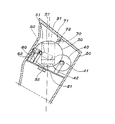
Fig. 2 is a sectional view showing the state of
shaking of an embodiment of the present invention;
Fig. 3 is a side view showing the internal mechanism
of the embodiment of Fig. 2;
Fig. 4 is a top view showing the internal mechanism of
the embodiment of Fig. 2;
2o Fig. 5 is a perspective sectional view showing a
weight added to the present invention;
Fig. 6 is a schematic view showing clockwise motion of
the embodiment of Fig. 3;
Fig. 7 is a schematic view showing counterclockwise
motion of the embodiment of Fig. 3.
DETAILED DESCRIPTION OF THE PREFERRED EMBODIMENT
Referring to Fig. 2, a hollow knob 20 of the joy stick
of the present invention is provided therein with a space
30 of suitable size formed by a partition plate 21 for
mounting therein a ball 30 added with a weight, and for
3

CA 02266187 1999-08-03
mounting therein a horizontal grating 40, a verticalY
grating 50, a supporting wheel 60 and a releasing-proof
device 70.
Referring together to Fig. 3 and 4, the horizontal
grating 40 and the vertical grating 50 are provided with a
coaxial roller 41 and a coaxial roller 51 respectively
contacting the ball 30. The ball 30 shown in Fig. 3 is
drawn with a horizontal central line 300, while a
horizontal central line c of the coaxial roller 41 and of
1o the coaxial roller 51 is preferably at the position a
distance "a" slightly lower than the horizontal central
line 300. The supporting wheel 60 is preferably provided
at a position having an equal angular distance to both the
coaxial roller 41 and the coaxial roller 51, and is also on
the horizontal central line c of the coaxial roller 41 and
the coaxial roller 51. A support 42 and a support 52
respectively of the coaxial roller 41 and the coaxial
roller 51 as well as a support 62 of the supporting wheel
60 are all provided on the partition plate 21.
20 As shown in Fig. 3, 5, in the preferred embodiment of
the present invention depicted therein, the ball 30 added
with a weight is provided near the bottom thereof with a
central through hole 31. Above a bottom surface 33 of the
central through hole 31, there is the weight 35 of which
the position is preferably lower than the horizontal
central line c.
Referring together to Fig. 2, 6 and 7, with the above
stated structure of joy stick, no matter how the knob 20 of
the joy stick moves, the ball 30 provided therein added
30 with the weight 35 has a vertical central line 303 thereof
always kept in its vertical position. While the coaxial
4

CA 02266187 1999-08-03
roller 41 and the coaxial roller 51 displace in pursuance
of moving of the knob 20 of the joy stick and are rubbed by
the ball 30 in rotation. In this way, the horizontal
grating 40 and the vertical grating 50 both are shaken to
obtain the required amount of displacement. Thereby,
moving or shaking of the joy stick can allow detection of
the amount of displacement.
In order to get larger stability in operation of the
whole joy stick, the central through hole 31 of the ball 30
is provided on the top thereof with a filler block 37 which
is pressed by the releasing-proof device 70. In
cooperation with this filler block 37, the releasing-proof
device 70 is provided on the top of and integrally with the
knob 20 of the joy stick with a cylinder 71 which has a
spring 72 therein. An exposed small ball 73 is provided in
front of the spring 72 for pressing the filler block 37.
By the fact that the present invention can obtain the
required amount of displacement during movement of itself,
the joy stick needs only a very small bottom receiving-seat
2o for electric connection. There is no more requirement of a
bottom receiving-seat with a large volume; this can largely
reduce the volume in manufacturing as well as in packaging.
Besides, without limitation of requiring a bottom
receiving-seat with a large volume, a user can operate the
joy stick in any comfortable posture.
Having thus described my invention, what I claim as
new and desire to be secured by Letters Patent of the
United States are:
5

Dessin représentatif
Une figure unique qui représente un dessin illustrant l'invention.
États administratifs

2024-08-01 : Dans le cadre de la transition vers les Brevets de nouvelle génération (BNG), la base de données sur les brevets canadiens (BDBC) contient désormais un Historique d'événement plus détaillé, qui reproduit le Journal des événements de notre nouvelle solution interne.

Veuillez noter que les événements débutant par « Inactive : » se réfèrent à des événements qui ne sont plus utilisés dans notre nouvelle solution interne.

Pour une meilleure compréhension de l'état de la demande ou brevet qui figure sur cette page, la rubrique Mise en garde , et les descriptions de Brevet , Historique d'événement , Taxes périodiques et Historique des paiements devraient être consultées.

Historique d'événement

Description Date
Inactive : CIB désactivée 2014-05-17
Inactive : CIB du SCB 2014-02-01
Inactive : CIB expirée 2014-01-01
Inactive : CIB attribuée 2013-02-04
Inactive : CIB désactivée 2011-07-29
Inactive : CIB dérivée en 1re pos. est < 2006-03-12
Inactive : CIB de MCD 2006-03-12
Le délai pour l'annulation est expiré 2004-03-19
Demande non rétablie avant l'échéance 2004-03-19
Réputée abandonnée - omission de répondre à un avis sur les taxes pour le maintien en état 2003-03-19
Inactive : Grandeur de l'entité changée 2002-03-26
Inactive : Page couverture publiée 2000-09-21
Demande publiée (accessible au public) 2000-09-19
Inactive : Correspondance - Formalités 1999-08-03
Inactive : CIB attribuée 1999-05-06
Inactive : CIB en 1re position 1999-05-06
Inactive : Certificat de dépôt - Sans RE (Anglais) 1999-04-22
Demande reçue - nationale ordinaire 1999-04-21

Historique d'abandonnement

Date d'abandonnement Raison Date de rétablissement
2003-03-19

Taxes périodiques

Le dernier paiement a été reçu le 2002-03-18

Avis : Si le paiement en totalité n'a pas été reçu au plus tard à la date indiquée, une taxe supplémentaire peut être imposée, soit une des taxes suivantes :

  • taxe de rétablissement ;
  • taxe pour paiement en souffrance ; ou
  • taxe additionnelle pour le renversement d'une péremption réputée.

Les taxes sur les brevets sont ajustées au 1er janvier de chaque année. Les montants ci-dessus sont les montants actuels s'ils sont reçus au plus tard le 31 décembre de l'année en cours.
Veuillez vous référer à la page web des taxes sur les brevets de l'OPIC pour voir tous les montants actuels des taxes.

Historique des taxes

Type de taxes Anniversaire Échéance Date payée
Taxe pour le dépôt - petite 1999-03-19
TM (demande, 2e anniv.) - petite 02 2001-03-19 2001-03-12
TM (demande, 3e anniv.) - générale 03 2002-03-19 2002-03-18
Titulaires au dossier

Les titulaires actuels et antérieures au dossier sont affichés en ordre alphabétique.

Titulaires actuels au dossier
LILY CHEN
Titulaires antérieures au dossier
S.O.
Les propriétaires antérieurs qui ne figurent pas dans la liste des « Propriétaires au dossier » apparaîtront dans d'autres documents au dossier.
Documents

Pour visionner les fichiers sélectionnés, entrer le code reCAPTCHA :


Pour visualiser une image, cliquer sur un lien dans la colonne description du document (Temporairement non-disponible). Pour télécharger l'image (les images), cliquer l'une ou plusieurs cases à cocher dans la première colonne et ensuite cliquer sur le bouton "Télécharger sélection en format PDF (archive Zip)" ou le bouton "Télécharger sélection (en un fichier PDF fusionné)".

Liste des documents de brevet publiés et non publiés sur la BDBC .

Si vous avez des difficultés à accéder au contenu, veuillez communiquer avec le Centre de services à la clientèle au 1-866-997-1936, ou envoyer un courriel au Centre de service à la clientèle de l'OPIC.

({010=Tous les documents, 020=Au moment du dépôt, 030=Au moment de la mise à la disponibilité du public, 040=À la délivrance, 050=Examen, 060=Correspondance reçue, 070=Divers, 080=Correspondance envoyée, 090=Paiement})


Description du
Document 
Date
(aaaa-mm-jj) 
Nombre de pages   Taille de l'image (Ko) 
Dessin représentatif 2000-09-20 1 11
Description 1999-03-18 5 185
Revendications 1999-03-18 1 37
Dessins 1999-03-18 5 79
Abrégé 1999-08-02 1 23
Revendications 1999-08-02 1 44
Description 1999-08-02 5 202
Dessins 1999-08-02 5 85
Abrégé 1999-03-18 1 21
Certificat de dépôt (anglais) 1999-04-21 1 164
Rappel de taxe de maintien due 2000-11-20 1 112
Courtoisie - Lettre d'abandon (taxe de maintien en état) 2003-04-15 1 176
Rappel - requête d'examen 2003-11-19 1 123
Correspondance 1999-04-26 1 24
Correspondance 1999-08-02 13 379