Note : Les descriptions sont présentées dans la langue officielle dans laquelle elles ont été soumises.
CA 02270548 2003-02-25
72956-71
WINTER PRECIPITATION MEASURING SYSTEM
FIELD OF THE INVENTION
This invention relates to the field of meteorological instrumentation, and
more
particularly to a system for quantifying the liquid equivalent of winter
precipitation that
reaches the Earth's surface and at what rate the winter precipitation reaches
the
Earth's surface.
PROBLEM
A snow gauge is the common name for a device designed to quantify the liquid
equivalent of winter precipitation that reaches the Earth's surface at a given
point on
the Earth's surface. For purposes of this document, winter precipitation
includes
frozen precipitation and supercooled precipitation including, but not limited
to, snow,
freezing drizzle, and supercooled drizzle. Existing snow gauges, however, rely
on an
inherently inaccurate technique of collecting and melting winter
precipitation, and
weighing the melted precipitation to estimate a total accumulation over time.
The
weighing type snow gauge accumulates winter precipitation in an accumulation
container as the winter precipitation free-falls into the accumulation
container. Ideally,
the winter precipitation free-falls into the accumulation container at the
same rate and
in the same quantity as the winter precipitation would fall in the immediate
snow
gauge vicinity. The accumulation container is charged with chemicals such as
an anti-
freeze solution made of ethylene glycol or a mixture of glycol and methanol,
or any
similarly functioning solution, to dissolve the winter precipitation and to
prevent the
liquefied sample contents of the accumulation container from refreezing. A
layer of oil
on the surface of the anti-freeze solution helps retard evaporation of the
anti-freeze
and any liquid collection sample within the accumulation container. The weight
of the
liquid collection sample is converted into a corresponding depth measurement
so that
the total accumulation of precipitation and the precipitation rate are
estimated over
time. Measurement resolutions of at or about 0.2 mm are achievable using a
weighing-type snow gauge. Weighing type snow gauges available in the industry
include, but are not limited to, the Universal gauge by Belfort, and the ETI
gauge by
Electronics
CA 02270548 1999-04-30
WO 98/20372 PCT/US97/19581
Techniques Incorporated. The Universal gauge is the preferred snow gauge and
the gauge used by the United States National Weather Service (NWS).
One problem with a weighing type snow gauge is that the overall accuracy
of the gauge is limited to mechanical resolutions of accumulation. Therefore,
a
light winter precipitation event of at or about 10mm of accumulation per hour
or
less, for example, can go completely undetected or there may be substantial
time
delays between accumulation reports during such an event. In either
circumstance,
existing snow gauges are unable to reliably and accurately report real-time
accumulation for such light precipitation events.
Another related problem with a weighing type snow gauge is that even
during a heavy winter precipitation event, there is a time delay between the
time
winter precipitation falls and the snow gauge detects or "tips" under the
weight of
a measurable accumulation of the winter precipitation. The time delay can be
from
a few minutes to 30 minutes or more, thereby making it difficult to accurately
determine a real-time precipitation rate.
Another problem with a weighing type snow gauge is that wind induced
measurement errors occur due to wind gusts that vibrate or sway the snow gauge
andlor the accumulation container in the snow gauge. Although the snow gauge
housing can be reenforced to withstand wind gusts without vibrating or
swaying,
the advantage gained by reenforcing is outweighed by the additional materials
and
manufacturing cost. Even if the snow gauge housing is reenforced, the
sensitivity
of the accumulation container inside the housing remains subject to vibration
andlor jostling due to wind gusts flowing through the substantially hollow
snow
gauge housing.
Another problem with weighing type snowgauges is the accumulation of
snowfall on the inner sidewalls of the gauge. This inner sidewall accumulation
inhibits true real-time recording of actual precipitation reaching the Earth's
surface
to an extent that the recorded precipitation rate is as much as 70% less than
the
actual precipitation rate.
Another problem with weighing snowgauges is that they can not distinguish
between types of precipitation that can exist at temperatures near or below
zero.
An example of the types of precipitation that can exist at temperatures near
or
below zero are snow and drizzle.
-2-
CA 02270548 2003-02-25
72956-71
Due to the problems with weighing-type snow gauges discussed
above, a high-accuracy low cost snow gauge is desirable that quantifies a
liquid
equivalent of the winter precipitation in true real-time at resolutions about
or
considerably less than 0.2 mm of accumulation. A snow gauge of the desired
type
has heretofore not been realized prior to the invention and claimed below.
SOLUTION
The above identified problems are solved and an advance achieved
in the field by the winter precipitation measuring system of the present
invention.
The winter precipitation measuring system is an unattended system that
quantifies
a liquid equivalent of winter precipitation such as snow or drizzle as
previously
defined in true real-time without requiring a chemically charged collection
container or other mechanically active components. The winter precipitation
measuring system includes an elongated tube, a thermal plate within the
elongated tube, and a method and apparatus for maintaining the thermal plate
at a
substantially constant temperature, and determining a precipitation rate in
response to maintaining the thermal plate at a substantially constant
temperature.
Maintaining the thermal plate at a substantially constant temperature includes
a
method and apparatus for sensing a temperature of the thermal plate, and
adjusting an amount of power to the thermal plate in response to the sensing.
2 o Determining a precipitation rate includes a method and apparatus for
quantifying
an amount of current required to maintain the thermal plate at said
substantially
constant temperature, and converting the amount of current to a precipitation
rate.
Determining whether the winter precipitation type, such as between snow or
drizzle, includes a method for analyzing power rise rates due to individual
particles
of winter precipitation that contact the thermal plate.
One broad aspect of the invention provides a winter precipitation
measuring system comprising: an elongated tube; a thermal plate mounted within
said elongated tube; means for maintaining said thermal plate at a
substantially
constant temperature; means for determining a precipitation rate in response
to
3 0 power consumption of said means for maintaining said thermal plate at said
substantially constant temperature in response to receipt of a present type of
3
CA 02270548 2003-02-25
72956-71
precipitation that is in contact with said thermal plate; means for
quantifying an
instantaneous change in power consumption of said thermal plate in response to
receipt of a present type of precipitation that is in contact with said
thermal plate;
and means for distinguishing among various types of precipitation in view of
said
instantance change in power consumption for each respective type of
precipitation.
Another broad aspect of the invention provides a method for
operating a winter precipitation measuring system comprising: mounting a
thermal plate within an elongated tube; maintaining said thermal plate at a
to substantially constant temperature; determining a precipitation rate in
response to
power consumption of said thermal plate at said substantially constant
temperature in response to receipt of a present type of precipitation that is
in
contact with said thermal plate; quantifying an instantance change in power
consumption of said thermal plate in response to receipt of a present type of
precipitation that is in contact with said thermal plate; and distinguishing
among
various types of precipitation in view of said instantance change in power
consumption for each respective type of precipitation.
BRIEF DESCRIPTION OF DRAWINGS
FIG. 1 illustrates an elevational perspective of a winter precipitation
2 o measuring apparatus of the present invention in block diagram form;
FIG. 2 illustrates an alternative embodiment of a winter precipitation
measuring apparatus having a camera attachment;
FIG. 3 illustrates a plan view of the winter precipitation measuring
apparatus in block diagram form;
2 5 FIG. 4 illustrates a new plan view cutaway of a thermal plate;
3a
CA 02270548 1999-04-30
WO 98/20372 PCT/US97/19581
FIG. 5 illustrates operational steps for the winter precipitation measuring
system in flow diagram form; and
FIG. 6 illustrates control electronics for the winter precipitation measuring
system in block diagram form.
DETAILED DESCRIPTION
Winter Precipitation Measuring Apparatus - FIGs. 1-2
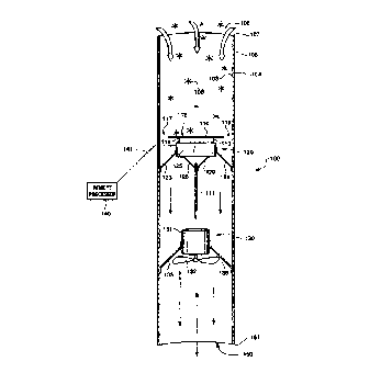
FIG. 1 illustrates an elevational perspective of a winter precipitation
measuring apparatus 100 used in the winter precipitation measuring system.
Winter precipitation measuring apparatus 100 is an elongated tube 105 having
an
inner surface 103, an outer surface 104, a first orifice 106 at a first end
107, and
a second orifice 150 at a second end 151 wherein the second end 151 is remote
from the first end 107. The elongated tube 105 contains sensor electronics
assembly 120 and a fan assembly 130 therein.
Sensor electronics assembly 120 includes a primary thermal plate 110, a
sensor control housing 125, a reference plate 111, and a communication link
141
to a remote processor 140. Primary thermal plate 110 is positioned within and
substantially perpendicular to elongated tube 105. The sensor control housing
125
contains processing electronics for collecting raw precipitation data. The
sensor
control housing 125 is positioned under primary thermal plate 110 for
protection
from external elements. Alternative sensor control housing 125 placements
include, but are not limited to, attached to the outer surface 104 of
elongated tube
105; operatively connected to the winter precipitation measuring apparatus 100
from a remote location, or any location within or proximate to elongated tube
105
provided that the location does not obstruct winter precipitation 108 from
free-
falling in direction A into elongated tube 105. Reference plate 111 is located
under
the sensor control housing 125 for protection from external elements.
Alternative
reference plate 111 placements and orientations exist provided the reference
plate
111 is subject to substantially the same ambient temperature andlor air flow
as the
primary thermal plate 110 while being protected from contact with winter
precipitation 108. An additional aerodynamic fairing may be necessary to
further
protect reference plate 111 in circumstances where wind, wind gust, or other
strong
turbulence are continuous andlor extreme enough to compromise the reliability
of
the reference pate 111 as a true reference. Another alternative is to include
CA 02270548 1999-04-30
WO 98/20372 PCT/US97%19581
redundant reference plates to facilitate a reference comparison. Remote
processor
140 collects data from the reference plate 111 and primary thermal plate 110
for
subsequent processing.
In one preferred embodiment, elongated tube 105 is oriented substantially
perpendicular to the Earth's surface with the first end 107 oriented
substantially
zenithally. Primary thermal plate 110 is positioned substantially
perpendicular
relative to the elongated tube 105 in a manner that provides substantially
uniform
air passages 117-118 between primary thermal plate 110 and the inner surtace
103
of the elongated tube 105. The preferred ratio of primary thermal plate 110
size
to air passage 117 and 118 size, is 1:1.
Fan assembly 130 is located proximate to the second end 151 of elongated
tube 105. Fan assembly 130 includes fan motor 131 and fan 132. Fan motor 131
is attached to the inside surtace 103 of elongated tube 105 by brackets 135-9
36.
Power for the electrical components within the winter precipitation measuring
apparatus 100 is typically in a remote site, such as at or near the remote
processor
140 for example. In one preferred embodiment, airflow through elongated tube
105
is in direction A in said first orifice 106 and out said second orifice 150.
In
conditions of substantially sustained wind, wind gusts, and/or strong
turbulence
conditions, a baffle or other shielding may be necessary to restrict air flow
through
elongated tube 105 in either direction.
In one preferred embodiment, primary thermal plate 110 is mounted on the
sensor control housing 125 by mounts 113-114 so that thermal surface 112 is
oriented substantially zenithally. Reference plate 111 is suspended from
sensor
control housing 125 by brackets 128-129 so that reference plate 111 is exposed
to the same ambient conditions as primary thermal plate 110 without being
subject
to contact with winter precipitation 108. Sensor control housing 125 is
attached to
the inside surface 103 of elongated tube 105 by brackets 123-124.
FIG. 2 illustrates an alternative embodiment of a winter precipitation --
measuring apparatus 100 of FIG. 1. In FIG. 2 the winter precipitation
measuring
apparatus 100 includes a fan assembly 130 and a sensor electronics assembly
120
within elongated tube 105 as disclosed in FIG. 1. However, the F1G. 2
embodiment
includes a transparent primary thermal plate 210, a mirror 230, and a camera
220.
The transparent primary thermal plate 210 is a heating element embedded within
-5-
CA 02270548 1999-04-30
WO 98/20372 PCTIUS97/19581
a transparent material. The mirror 230 is a standard reflective mirror that
faces a
camera port 222 and is supported at a predetermined fixed angle by mirror
support
231. The camera 220 is mounted at camera port 222 in elongated tube 105. The
main body of camera 220 is supported outside elongated tube 105 by camera
support 221. By positioning the mirror 230 at the proper angle, camera 220 can
view the winter precipitation 108 landing on the exposed surface 212 of
transparent
thermal plate 210 by way of mirror 230. The ability to view the winter
precipitation
108 on exposed surface 212 provides valuable real-time visibility data
feedback so
that actual events at the measuring apparatus 100 location can be monitored
remotely when camera 220 is a video camera.
Thermal Plate Details - FIGs. 3-4
FIG. 3 illustrates the preferred geometric shape of the winter precipitation
measuring device 100 and the primary thermal plate 110 when viewed from either
first end 107 or second end 151. However, the shape can be any shape in the
geometric spectrum of curvilinear to multi-sided provided that the geometric
shape
provides complete 360° continuity with itself and the primary thermal
plate 110 is
centered within the walls of inner surface 103 of elongated tube 105 allowing
an
air passage 117-118. The circular geometric shape of elongated tube is about
20
to 30.5 cm diameter for inner surface 103.
FIG. 4 illustrates a plan view cutaway of primary thermal plate 110. Primary
thermal plate 110 and reference plate 111 are identical in their physical
construction and are standard among the thermal plates that are readily
available
in the industry. The geometric shape of primary thermal plate 110 and
reference
plate 111 can be any shape in the geometric spectrum from curvilinear to multi-
sided provided that the geometric shape allows clearance for air passages 117-
118
around the entire plate. In the preferred embodiment thermal plate 110 is
constructed of materials having a uniformly low thermal capacity in a
configuration
such as an aluminum substrate 420, a thermal element grid layer 410, and a
thermal conductive sealing layer 405.
Operational Steps - FIG. 5
FIG. 5 illustrates the operational steps 500 in flow diagram form for the
winter precipitation measuring system of the present invention. The system
begins
at step 504 and proceeds to system initialization at step 507. System
initialization
-6-
CA 02270548 1999-04-30
WO 98/20372 PCTlUS97119581
507 includes, but is not limited to, heating primary thermal plate 110 and
reference
plate 111 to a predetermined operating temperature, and calibrating the
primary
thermal plate 110 with the reference plate 111. The optimal operating
temperature
for primary thermal plate 110 and reference plate 111 is below the local
boiling
point of water yet hot enough to evaporate the winter precipitation
substantially
instantaneously, where substantially instantaneously can be as much as 5-10
seconds. The operating temperature is programmable and adjustable depending
on critical operating conditions that include, but are not limited to,
precipitation rate,
ambient temperature, humidity, and crystal size. For example, small crystal
sizes
evaporate more quickly than large crystal sizes falling at the same rate so
That the
operating temperature can be lower for small crystal sizes.
System initialization at step 507 also includes powering up fan motor 131 to
a speed so that fan 132 pulls air in direction B past primary thermal plate
110 and
out the second orifice 150. Fan 132 must draw enough air past primary thermal
plate 110 so that a convecting heat plume does not develop at or above the
first
orifice 106 thereby preventing winter precipitation from entering and striking
primary thermal plate 110. An additional purpose of the fan 132 is to impose a
uniform air flow velocity in direction B past sensor electronics assembly 120.
When primary thermal plate 110 and reference plate 111 are at an optimal
operating temperature for present conditions, a continuous cycle begins for
both
thermal plates. The temperature of the primary thermal plate 110 is tested at
step
514. If the temperature is above or below an ideal predetermined temperature
setting at decision step 518 then the current to the primary thermal plate 110
is
adjusted accordingly at step 519 to maintain the idea! predetermined
temperature
and processing continues at step 514. If the temperature is at the ideal
predetermined temperature setting at decision step 518 then processing
continues
at step 514.
Substantially concurrently with the continuous process of steps 514, 518,
and 519, the temperature of the reference plate 111 is tested at step 520. If
the
temperature is above or below an ideal predetermined temperature setting at
decision step 525 then the current to the reference plate 111 is adjusted
accordingly at step 528 to maintain the ideal predetermined temperature and
processing continues at step 520. If the temperature is at the ideal
predetermined
_7_
CA 02270548 1999-04-30
WO 98/20372 PCT/US97119581
temperature setting at decision step 525 then processing continues at step
520.
Note that the steps of controlling temperature by controlling current to the
reference
plate 111 and/or primary thermal plate 110, could alternatively be by
controlling
voltage so that a constant power setting is achieved for reference plate 111
and/or
primary thermal plate 110.
Substantially concurrently with the continuous temperature testing process
for the primary thermal plate 110 and the reference plate 111 defined above,
the
amount of current being drawn by the primary thermal plate 110 and the
reference
plate 111 are compared at step 530. As the winter precipitation 108 strikes
the
primary thermal plate 110, the winter precipitation substantially
instantaneously
melts and evaporates thereby cooling the first surface 112 of the primary
thermal
plate 110. The reference plate 111 is exposed to the same ambient
environmental
conditions as primary thermal plate 110 except for contact with any winter
precipitation. Thus, the difference in the power consumption of the primary
thermal
plate 110 versus the reference plate 111 is directly proportional to the rate
of winter
precipitation falling on the primary thermal plate 110. Further, since the
individual
melting particles of the winter precipitation have a different power
consumption
curve than non-melting particles, winter precipitation types such as snow and
drizzle can be distinguished by comparing the respective power consumption
curves.
The power consumption by both the primary thermal plate 110 and the
reference plate 111, and the difference in power consumption, is recorded with
a
time stamp in the sensor electronics housing 125 at step 537. At step 539 the
time
dated precipitation rate is calculated based on the difference in amps. At
step 542,
remote processor 140 periodically polls the local processor in the sensor
electronics housing 125 to retrieve the precipitation data for further
processing and
recording along with the data from other snow gauge systems.
If the power consumption sensing and data recording is to continue at
decision step 550, processing continues at step 530. If the power consumption
sensing and data recording is not to continue at decision step 550, then
processing
quits at step 554.
_g_
CA 02270548 2003-02-25
72956-71
Control Electronics - FIG. 6
FIG. 6 illustrates control electronics for the winter precipitation measuring
system in block diagram form. The winter precipitation measuring system is
powered
by 110 V AC or in the alternative by 12 V DC for remote operations. In either
case the
voltage source 610 with appropriate grounding 605, provides power for the
entire
system.
Fan motor 131 is powered by way of a voltage regulator 614. Primary thermal
plate 110 is connected in a loop with thermistor 628 to test temperature, and
amp
controller 625 to adjust the current to primary thermal plate 110 as needed.
Microprocessor 630 compares, time stamps the data on current draw by the
primary
thermal plate 110, and transmits the data to a remote processor 635 for final
precipitation rate calculations. Similarly, reference plate 111 is connected
in a loop
with thermistor 620 to test temperature, and amp controller 618 to adjust the
current to
reference plate 111 as needed. Microprocessor 630 compares and time stamps the
data on current draw by the reference plate 111, and transmits the data to a
remote
processor 635 for final precipitation rate calculations.
_g_