Note : Les descriptions sont présentées dans la langue officielle dans laquelle elles ont été soumises.
CA 02271225 2006-05-19
Hydraulic Elevator
The invention relates to a hydraulic elevator with a car, at least one door,
one guide rail
which guides the car along its hoisting travel, a hydraulic jack having one or
more
pistons which are telescopically extendable from a cylinder, the jack being
fixed in
position at one end, and the cylinder being fastened to a floor of the car
with a fastening
device in such a way that the car moves with it in its direction of travel.
Elevators of this type are already known. They can be classified into three
different
types of construction, depending on how the elevator car is fastened to the
hydraulic
j ack.
A common arrangement is for the car to rest on a platform on the end face of
the jack. A
disadvantage of this configuration is the large amount of space required by
the retracted
jack. Besides this arrangement with the jack under the car, there is the so-
called
rucksack arrangement, in which the jack passes behind the car and acts on the
upper part
of a frame which carries the car. The point of attachment is defined by the
prescribed
height of the upper part of the frame. Consequently, depending on the type of
car and
the specified height of attachment to the upper part of the frame, a jack with
a
correspondingly long cylinder is required. In some cases an additional
extension to the
cylinder is used for this purpose, or an extra long cylinder is chosen, to
meet the
requirements for attachment.
Finally, the third type of construction is disclosed in the unexamined German
patent
application DE-OS 2062161. With this arrangement a supporting framework and
the car
together form a self contained module which is pre-assembled and needs only to
be
placed in position at the installation location. Two guide rails at the sides
are joined
together at their upper ends by means of a crossbeam to form the supporting
framework.
The upper ends of two telescopic jacks are attached to the crossbeam, while
the lower
ends of the telescopic jack are fixed at the car. The jacks are accommodated
together
with the guide rails in recesses on opposite sides in the car walls. The
pistons of the
jacks are fixed rigidly to the crossbeam, and the lower ends of the cylinders
are bolted to
CA 02271225 2006-05-19
2
lateral projections from the floor of the car. As the piston is fastened to
the crossbeam,
the cylinder and the car fastened to it rise when pressure is applied.
Although this type of hydraulic drive for elevators avoids the need for
hollowed out
spaces below the floor of the lowest landing, and long overtravel at the upper
end of the
hoistway, it nevertheless has the disadvantage that it is only suitable for
elevator
installations with a limited travel height. The hydraulic jacks are also
especially costly,
as it is essential for their cylinders to be at least as long as the intended
hoisting distance.
It is an object of the present invention designing an elevator installation
with a hydraulic
drive which is simply constructed, and which can be installed with a small
amount of
effort, which is independent of the travel height to be served.
According to the invention, the solution to the problem is provided by a
hydraulic
elevator with a car, at least one door, one guide rail which guides the car
along its
hoisting travel, a hydraulic jack having one or more pistons which are
telescopically
extendable from a cylinder, the jack being fixed in position at one end, and
the cylinder
being fastened to a floor of the car with a fastening device in such a way
that the car
moves with it in its direction of travel, wherein the telescopic hydraulic
jack projects
through the floor and into the car.
The essence of the invention is that the hydraulic jack projects through the
floor of the
car into the car, the jack and the car being joined together at the car floor.
Depending on
the length of the jack in its retracted state, which depends on the travel
height, the jack
projects either into the car, or through it and out of the car roof. This
makes it possible to
use jacks with a greater compression length, and therefore longer travel, or
for
applications with limited travel height, hydraulic jacks can be chosen with a
cylinder
length less than was necessary until now to fasten them to the car. As a
result, it is now
possible to select a jack independent of the length available for its
installation, and there
is also no need for the cylinder extensions required until now, which reduces
costs.
If the jack passes through the car close to the front of the car, which is
anyway covered
by the open door, there is hardly any reduction in the space inside the car.
An additional
CA 02271225 2006-05-19
2a
advantage of this arrangement is the resulting location close to the edges of
the car.
These areas of high structural rigidity are especially suitable for
transmitting the
load-bearing forces from the fastening device into the car. So as to transmit
these forces
to the car structure over as large an area as possible, the fastening device
includes a
supporting plate, which is positioned essentially at right angles to the
longitudinal axis of
the cylinder, and whose position on the cylinder in the direction of travel is
fixed.
Besides the advantage of transmitting the forces in this way, an additional
advantage is
that the car rests more or less on the surface of the supporting plate, and
simple means of
fastening are therefore adequate to hold it in position.
CA 02271225 1999-OS-07
3
It is especially easy to mount and fasten the supporting plate on the cylinder
if the supporting
plate has a centrally positioned opening, corresponding approximately to the
cross sectional
area of the cylinder, and needs only to be pushed onto the cylinder. To align
the supporting
plate perfectly perpendicular relative to the longitudinal axis of the
cylinder, it has proved very
helpful to use a guide. This can, for example, consist of a short length of
pipe, which at one
end is aligned coaxially with the opening and fastened to the supporting
plate, and at the other
end pushed onto the cylinder, which has the same diameter. A low-cost version
of the
supporting plate, which also saves weight, consists of a welded construction,
for which
available semifinished products can be used, and the necessary rigidity is
obtained by mounting
on the side of the plate facing away from the car elements in the form of
gussets to stiffen the
structure.
A further prefered embodiment of the invention especially suitable for
hydraulic elevators with
a long hoisting travel, uses a jack having two or more pistons which can be
extended
telescopically from a cylinder which is fitted with a mechanical
synchronization device of a type
already known, and which causes the extended lengths of adjacent telescopic
parts to be equal
at any position of extension. The connectors for the synchronization device
also pass by one of
their ends through the opening in the floor of the car together with the
telescopic jack, and are
fastened in position at an appropriate height. This version dispenses with the
points of
attachment to the hoistway walls which were usual until now. There is also an
embodiment of
the invention which dispenses entirely with fastening points of this kind, in
which all the free
ends of the connectors are pulled up to the upper end of the hoistway and
fastened to a
crossbeam. The crossbeam joins two guide rails for the car, which are located
to the side of the
telescopic jack. This version of the mufti-story elevator is also constructed
as a single module
which is delivered pre-assembled and needs only to be placed in position.
A fiuther version, which is very compact, has a synchronization device for
harmonizing the
travel of the cylinders of the teleskopic jack and also a special arrangement
of the rope sheaves
or toothed pulleys over which the connectors run, which is a special feature
of this version.
The axes of these pulleys, when viewed in the horizontal plane, are arranged
so as to form an
acute angle relative to an imaginary line connecting the two laterally
positioned guide rails. By
taking this measure, and by positioning the connectors correspondingly, it is
possible to
significantly reduce the distance between the ends of the connectors that pass
through the car
CA 02271225 1999-OS-07
4
and the telescopic jack, which also makes it possible to reduce the dimensions
of the opening in
the floor of the car, and of the entire space through which the connectors
pass.
In the following a more detailed description of the invention is given, based
on an example and
related to the attached drawings. These show:
Figure 1: A perspective view of an elevator installation with a telescopic
jack with a
synchronization device;
Figure 2: A partial view of the telescopic jack of the elevator installation
illustrated in
Figure 1;
Figure 3 : A cross-section of the arrangement of the rope sheaves or toothed
pulleys
taken on the plane III-III and viewed in the direction shown in Figure 2.
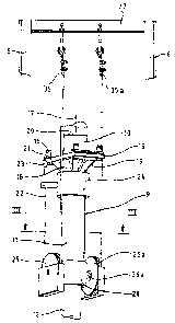
Figure 1 shows a hydraulic elevator installation with a self supporting car 1.
In the manner well
known, on the front side of the car 1 a telescopic door 2 is fitted, which by
means of a door
drive 3 positioned above it, and in response to an appropriate control signal,
can be retracted
laterally in the direction of the arrow 4, or extended in the direction
opposite to the arrow 4.
The complete car 1 is held between two guide rails 5, 6 positioned on opposite
sides and
permanently fastened to the building (not shown), and by means of a telescopic
jack 9 can be
moved along their vertical direction along the hoisting wayl.
The telescopic jack consists essentially of a cylinder 10, a middle piston 11,
and an end piston
12, the middle piston I 1 and the end piston 12 being telescopically
extendable out of the
cylinder 10. The telescopic jack 9 is a so-called synchronized jack which is
fitted with a
synchronization device, which causes the lengths of adjacent parts of the
telescope 10, I 1 and
12 to be equal at any position of its travel, and which is described in more
detail below in
relation to Figure 2.
The telescopic jack 9 is fastened by the end face of the end piston 12, and by
means of a jack
console 13, to the floor 7 of the hoistway and runs essentially parallel to
the guide rails S, 6.
The cylinder 10 of the jack 9 passes through the front part of the car close
to the door 2, and
depending on the length required, projects freely and unhindered for an
unlimited distance
above the car 1. The car 1 rests with the underside of the car floor 14 on the
supporting plate
CA 02271225 1999-OS-07
15 to which it is fastened with wheel studs 16. Isolating material can also be
inserted between
the supporting plate 1 S and the car floor to prevent transmission of
vibration to the car.
In this connection it is especially advantageous to use wheel studs 16 which
have a self
5 centering head and are secured against turning. When the screws are
tightened, the centering
on the head of the screws 16 eliminates any play in the screw holes, and
automatically aligns
the telescopic jack 9 in relation to the car 1 and the guide rails 5, 6. The
supporting plate 15 is
either welded or permanently fastened by other appropriate means onto the end
of the cylinder
facing the floor 7 of the hoistway. The height at which the supporting plate
15 is fixed
10 depends on the length of overtravel, the length of the hoistway, the
traveling speed of the
elevator, the number of telescopic piston stages 12, 1 l, etc.
As shown in Figure 2, the supporting plate 15 consists of a welded
construction in which a
rectangular plate 21 has a centrally positioned circular opening (not shown)
whose diameter
corresponds to the diameter of the cylinder 20. On the underside of the plate
21 a short length
of pipe 18 is welded to it by its end, and coaxial with the circular opening.
This serves as a
guide to align the supporting plate 15 relative to the longitudinal axis of
the cylinder 17. The
supporting plate 15 also has gussets 19 which stiffen the plate 21 relative to
the short length of
pipe 18
Figure 2 shows part of the synchronized telescopic jack 9 with the
synchronization device
mentioned above, which in the version shown as an example joins the telescopic
parts
consisting of the cylinder 10 the middle piston 11 and the end piston 12 by
means of two so-
called 2:1 suspenders. The suspenders are identically constructed, but located
on opposite
sides of the telescopic jack 9. Each suspender consists of a rope 22 (or a
chain, or similar), one
end 23 of which is fastened to the sleeve 24 of the cylinder 10, and then
passes over a sheave
25, thereby having its direction changed by 180 degrees, and according to the
invention then
passes in an essentially vertical direction through the floor 14 of the car
and through the car 1
itself to a crossbeam 27 at the top end of the hoistway, where the second end
35 of the rope is
fastened. The crossbeam 27 consists o~ for example, an L-profile, and forms a
rigid connection
between the guide rails 5, 6. Due to the connection via the rope 22 the middle
piston I 1 can
for any given travel distance of the cylinder 10 only be extended by half of
this distance.
CA 02271225 1999-OS-07
6
Consequently, the partial extensions of each telescopic part 10, 11, 12 are
identical for any
travel position.
Fastening the two rope ends 35, 35a to the crossbeam 27 represents a
simplification by
comparison with existing methods.
As can be seen in Figure 3, the sheaves 25, 25a located on opposite sides of
the sleeve 28 of
the middle piston 11 have axes of rotation 26, 26a which are not coaxially
aligned, but which
form in the horizontal plane an acute angle 32 relative to an imaginary line
31 drawn between
the two guide rails 5, 6 at the sides. This arrangement of the sheaves 25, 25a
makes it possible
for the ends of the ropes that pass through the car 1 to the crossbeam 27 to
run closer to the
telescopic jack, thereby saving space.
The situation described above in relation to a two-stage telescopic jack 9 can
be applied
correspondingly to multi-stage telescopic jacks.