Sélection de la langue

Search

Sommaire du brevet 2272428 

Énoncé de désistement de responsabilité concernant l'information provenant de tiers

Une partie des informations de ce site Web a été fournie par des sources externes. Le gouvernement du Canada n'assume aucune responsabilité concernant la précision, l'actualité ou la fiabilité des informations fournies par les sources externes. Les utilisateurs qui désirent employer cette information devraient consulter directement la source des informations. Le contenu fourni par les sources externes n'est pas assujetti aux exigences sur les langues officielles, la protection des renseignements personnels et l'accessibilité.

Disponibilité de l'Abrégé et des Revendications

L'apparition de différences dans le texte et l'image des Revendications et de l'Abrégé dépend du moment auquel le document est publié. Les textes des Revendications et de l'Abrégé sont affichés :

  • lorsque la demande peut être examinée par le public;
  • lorsque le brevet est émis (délivrance).
(12) Brevet: (11) CA 2272428
(54) Titre français: ACCUMULATEUR ELECTRIQUE
(54) Titre anglais: SECONDARY BATTERY
Statut: Durée expirée - au-delà du délai suivant l'octroi
Données bibliographiques
(51) Classification internationale des brevets (CIB):
  • H01M 10/00 (2006.01)
(72) Inventeurs :
  • PARK, UN SICK (Republique de Corée)
  • SONG, YOUNG BAE (Republique de Corée)
(73) Titulaires :
  • SAMSUNG DISPLAY DEVICES CO. LTD.
(71) Demandeurs :
  • SAMSUNG DISPLAY DEVICES CO. LTD. (Republique de Corée)
(74) Agent: MOFFAT & CO.
(74) Co-agent:
(45) Délivré: 2007-01-09
(86) Date de dépôt PCT: 1998-04-06
(87) Mise à la disponibilité du public: 1999-06-03
Requête d'examen: 2002-11-28
Licence disponible: S.O.
Cédé au domaine public: S.O.
(25) Langue des documents déposés: Anglais

Traité de coopération en matière de brevets (PCT): Oui
(86) Numéro de la demande PCT: PCT/KR1998/000082
(87) Numéro de publication internationale PCT: KR1998000082
(85) Entrée nationale: 1999-05-18

(30) Données de priorité de la demande:
Numéro de la demande Pays / territoire Date
97-62414 (Republique de Corée) 1997-11-24

Abrégés

Abrégé français

Accumulateur électrique composé d'un récipient métallique dans lequel est introduit un ensemble électrode, d'un ensemble couvercle monté sur une ouverture du récipient métallique et d'un orifice d'injection d'électrolyte situé sur au moins un du récipient métallique et de l'ensemble couvercle, ainsi que d'un élément de sécurité servant à fermer ledit orifice. Cet orifice est placé sur une partie négative de l'ensemble couvercle. L'élément de sécurité est introduit dans l'orifice d'injection d'électrolyte et soudé à ce dernier.


Abrégé anglais


A secondary battery comprises a can into which an electrode
assembly is inserted, a cap assembly mounted to an opening of the can; and
an electrolyte injection hole formed on at least one of the can and cap
assembly, and a safety member to close the electrolyte injection hole. The
electrolyte injection hole is formed on a negative portion of the cap
assembly. The safety member is inserted into and welded on the
electrolyte injection hole.

Revendications

Note : Les revendications sont présentées dans la langue officielle dans laquelle elles ont été soumises.


What is claimed is:
1. ~A secondary battery comprising a can and a cap assembly, and further
comprising:
an electrolyte injection hole formed on at least one of the can and the cap
assembly; and
a safety member to close the electrolyte injection hole, the safety member
breakable for reducing an internal pressure in the can once the internal
pressure
exceeds a predetermined level.
2. ~A secondary battery of claim 1, wherein the electrolyte injection hole is
formed on a negative electrode portion of the cap assembly.
3. ~A secondary battery of claim 1, wherein the safety member is inserted into
and welded on the electrolyte injection hole.
4. ~A secondary battery of claim 2, wherein the safety member is disposed on
the electrolyte injection hole and is welded on the negative electrode portion
thereof.
5. ~A secondary battery of claim 1, wherein the safety member is made of a
material selected from the group consisting of aluminum, nickel. stainless
steel, and
nickel gilding steel plate.
6. ~A secondary battery of claim 1, wherein the safety member is designed to
be broken by battery pressure of about 10-30 kgf/cm2.
7. ~A secondary battery of claim 2, wherein the safety member is provided with
a plurality of grooves.
7

8. A secondary battery of claim 7, wherein the safety member is inserted into
and welded on the electrolyte injection hole.
9. A secondary battery of claim 7, wherein the safety member is disposed on
the electrolyte injection hole and is welded on the negative electrode portion
thereof.
10. A secondary battery of claim 7, wherein the safety member is made of a
material selected from the group consisting of aluminum, nickel, stainless
steel and
nickel gilding steel plate.
11. A secondary battery of claim 7, wherein the safety member is designed to
be broken by battery pressure of about 10-30 kgf/cm2.
8

Description

Note : Les descriptions sont présentées dans la langue officielle dans laquelle elles ont été soumises.

CA 02272428 1999-OS-18
SECONDARY BATTERY
TECHNICAL FIELD
The present invention relates to a secondary battery and, more
particularly, a safety system of a secondary battery which can reduce
internal pressure thereof to prevent the explosion of the secondary battery.
BACKGROUND ART
Generally, a secondary battery is a rechargeable battery such as a
1 o nickel-metal hydride battery, a lithium battery or a lithium-ion battery
which is widely used in many applications. Such a secondary battery is
subject to high internal pressures due to gases generated by chemical
reactions when it is discharged and recharged. Though not common, it is
possible for the battery to explode as a result of the gases produced.
Therefore, many presently known secondary batteries have a cap
assembly provided with a safety valve which can discharge gases through a
discharge hole formed on a cap cover so as to reduce the pressure in the
batteries when the pressure in the battery is excessively raised.
The lithium-ion battery comprises an electrode assembly inserted
2o into a cap. A cap assembly is mounted on an upper end of the can.
Electrolyte is injected into the can through an inlet port formed on the cap
assembly. Insulating members are disposed between the electrode
assembly and the can.
Referring to Fig. 3, there is shown a conventional cap assembly 2.
The cap assembly 2 comprises a negative portion 4 welded on an upper end
of the can, a positive portion 6 disposed on a central portion of the negative
portion 4, and an insulating plate 8 disposed between the negative portion 4
and positive portion 6. A rivet 10 penetrates through the negative potion 4
and positive portion 6 is coupled to the positive electrode of the roll
3o electrode assembly.
In the above described conventional lithium-ion battery, if the
1

CA 02272428 2005-10-28
pressure within the battery is abruptly increased by the gas generated
therein, the
battery may explode. Thus, there is provided gas release means in the
secondary
battery.
'That is, safety grooves 12 are formed in the negative portion 4 of the cap
assembly 2 through a mechanical process, etching or electrofoaming process.
The
safety grooves 12 are broken open when the internal pressure of the battery is
increased above a predetermined level, thereby preventing the batter's I-rom
exploding.
An electrolyte injection hole 14 is formed on the negative portion 4 of the
cap assembly 2. After the electrolyte is injected through the hole 14, a plug
16 is
snugly f tted into the hole 14 and is then welded to provide a seal.
FIG. 4 shows another example of a conventional cap assembly 2.
In this example, a ball(not shown) is inserted into the injection hole 18 and
is then welded to provide a seal.
In the above described conventional cap assembly shown in FIGS. 3 and 4,
since the safety grooves and the electrolyte injection hole are formed on the
negative portion which is small in size, it is difficult to design and
manufacture the
same.
In the conventional cap assembly shown in FIG. 4, since the diameter of the
injection hole is small, it is difficult to inject electrolyte into the can.
DISCLOSURE OF INVENTION
Therefore, the present invention has been made in an effort to solve the
above described drawbacks of the prior art.
It is an object of the present invention to provide a cap assembly for a
secondary battery, in which safety means can precisely operate at a pre-set
pressure
to prevent the battery from exploding.
It is another object of the present invention to provide a cap assembly in
which the safety means can be easily formed, thereby reducing
2

CA 02272428 2005-10-28
manufacturing costs.
To achieve the above objects, the present invention provides a secondary
battery comprising a can and a cap assembly, and further comprising: an
electrolyte
injection hole formed on at least one of the can and the cap assembly; and a
safety
member breakable by a predetermined battery pressure to close the electrolyte
injection hole.
Preferably, the electrolyte injection hole is formed on a negative portion of
the cap assembly.
Preferably, the safety member is inserted into and welded on the electrolyte
injection hole.
Alternatively, the safety member is disposed on the electrolyte injection hole
and is welded on the negative portion.
Preferably, the safety member is made of a material selected from the group
consisting of aluminum, nickel, stainless steel, and nickel gilding steel
plate.
Preferably, the safety member is designed to be broken by battery pressure
of about 10-30 kgf/cm2.
Alternatively, the safety member is provided with a plurality of grooves.
BRIEF DESCRIPTION OF DRAWINGS
The present invention will become more fully understood from the detailed
description given hereinbelow and the accompanying drawings which are given by
way of illustration only, and thus are not limitative of present invention and
wherein:
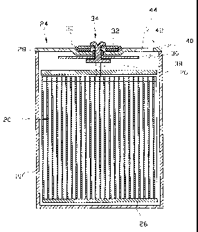
I~ IG. 1 is a cross sectional view illustrating a secondary battery where a
cap
assembly according to a preferred embodiment of the present invention is
employed;
FIG. 2 is a plane view illustrating a cap assembly of a secondary battery
according to a preferred embodiment of the present invention;
FIG. 3 is a plane view illustrating a conventional cap assembly ol~ a
3

CA 02272428 1999-OS-18
secondary battery; and
Fig. 4 is a plane view illustrating another conventional cap assembly
of a secondary battery.
BEST MODE FOR CARRYING OUT THE INVENTION
The following is the description of the preferred embodiments
according to the present invention. In the drawing, like reference
numerals have been used to identify like elements in each figure.
Referring first to Figs. 1 and 2, there are respectively shown a
sectional view of a secondary battery where a cap assembly 24 according to
the present invention is employed and a plane view of the cap assembly 24.
The cap assembly 24 of the present invention is coupled on an upper
end of a can 22 in which a roll electrode assembly 20 consisting of a
positive electrode, a negative electrode, and a separator, and electrolyte are
~5 received. The can 22 contacts the negative electrode by a tap (not shown).
Insulating plates 26 are provided at upper and lower ends of the
electrode assembly 20 to prevent the electrode assembly 20 from contacting
the cap assembly 24 and the can 22.
The cap assembly 24 comprises a negative portion 28 which is
2o welded to the upper end of the can 22, a positive portion 32 fomned on a
central portion of the negative portion 28, and a rivet 34 mounted
penetrating a central portion of the negative portion 28 and positive portion
32. An insulating member 30 is disposed between the negative portion 28
and positive portion 32. The rivet 34 is used as coupling means for
25 coupling the positive portion 32 with the negative portion 28. An
insulating member 36 is disposed between the rivet 34 and the negative
portion 28. The rivet 34 is connected to the positive electrode of the
electrode assembly through a tap 38. That is, the rivet is used as a
terminal for connecting the positive electrode to the positive portion 32.
3o An electrolyte injection hole 40 is formed on the negative portion 28 to
inject electrolyte into the can.
4

CA 02272428 2005-10-28
Although, in this embodiment, an electrolyte injection hole 40 is formed on
the
negative portion 28, the location of the electrolyte injection hole 40 is not
limited
to this structure but can be formed on the can 22.
After the electrolyte is injected into the can 22, the injection hole 40 is
tightly closed by a safety plate 42. In this embodiment, the safety plate 42
tray be
formed having the same size as that of the injection hole and inserted into
and
welded on the injection hole 40.
Alternatively, the safety plate 42 may be formed having the larger size as
that
of the injection hole 40 and is positioned to cover the injection hole 40.
~I~he safety
plate 42 positioned on the injection hole 40 is welded on the negative portion
28.
rfhe safety plate 42 is for preventing the explosion ofthe battery. That is,
The
safety plate 42 is formed having the thickness or rigidity less than that of
the
negative portion 28.
Alternatively, in the case where the safety plate 42 is made in the same
material as the negative portion 28, safety grooves 44 are formed on the
safety plate
42 through a mechanical process, etching or electrofoaming process. The safety
plate 42 are broken open when the internal pressure of the battery is
increased
above a predetermined level, thereby preventing the battery from exploding.
More in detail, the safety plate 42 may be made of a material selected from
the group consisting of aluminum, nickel, stainless steel, and nickel gilding
steel
plate.
Preferably, the safety plate 42 is designed to be broken by the internal
pressure of about 10-30 kgf/cmZ.
Therefore, when the internal pressure of the battery is increased above a
predetermined level by gas generated when the battery is charged and
discharged,
the safety plate 42 is removed or cracked, thereby enabling gas from the
battery to
be exhausted to reduce the internal pressure.
While this invention has been described in connection with what is presently
considered to be the most practical and preferred embodiments, it
5

CA 02272428 1999-OS-18
is to understood that the invention is not limited to the disclosed
embodiment, but, on the contrary is intended to cover various modifications
and equivalent arrangements and methods included within the spirit and
scope of the appended claims.
10
20
30
6

Dessin représentatif
Une figure unique qui représente un dessin illustrant l'invention.
États administratifs

2024-08-01 : Dans le cadre de la transition vers les Brevets de nouvelle génération (BNG), la base de données sur les brevets canadiens (BDBC) contient désormais un Historique d'événement plus détaillé, qui reproduit le Journal des événements de notre nouvelle solution interne.

Veuillez noter que les événements débutant par « Inactive : » se réfèrent à des événements qui ne sont plus utilisés dans notre nouvelle solution interne.

Pour une meilleure compréhension de l'état de la demande ou brevet qui figure sur cette page, la rubrique Mise en garde , et les descriptions de Brevet , Historique d'événement , Taxes périodiques et Historique des paiements devraient être consultées.

Historique d'événement

Description Date
Inactive : Périmé (brevet - nouvelle loi) 2018-04-06
Accordé par délivrance 2007-01-09
Inactive : Page couverture publiée 2007-01-08
Inactive : Taxe finale reçue 2006-11-02
Préoctroi 2006-11-02
Un avis d'acceptation est envoyé 2006-09-21
Lettre envoyée 2006-09-21
Un avis d'acceptation est envoyé 2006-09-21
Inactive : Approuvée aux fins d'acceptation (AFA) 2006-09-12
Modification reçue - modification volontaire 2006-07-24
Inactive : Dem. de l'examinateur par.30(2) Règles 2006-01-26
Modification reçue - modification volontaire 2005-10-28
Inactive : Dem. de l'examinateur par.30(2) Règles 2005-04-28
Lettre envoyée 2002-12-18
Exigences pour une requête d'examen - jugée conforme 2002-11-28
Toutes les exigences pour l'examen - jugée conforme 2002-11-28
Requête d'examen reçue 2002-11-28
Lettre envoyée 1999-08-18
Inactive : Page couverture publiée 1999-08-11
Inactive : Transfert individuel 1999-07-15
Inactive : CIB attribuée 1999-07-14
Inactive : CIB en 1re position 1999-07-14
Inactive : Lettre de courtoisie - Preuve 1999-06-29
Inactive : Notice - Entrée phase nat. - Pas de RE 1999-06-23
Demande reçue - PCT 1999-06-18
Demande publiée (accessible au public) 1999-06-03

Historique d'abandonnement

Il n'y a pas d'historique d'abandonnement

Taxes périodiques

Le dernier paiement a été reçu le 2006-02-13

Avis : Si le paiement en totalité n'a pas été reçu au plus tard à la date indiquée, une taxe supplémentaire peut être imposée, soit une des taxes suivantes :

  • taxe de rétablissement ;
  • taxe pour paiement en souffrance ; ou
  • taxe additionnelle pour le renversement d'une péremption réputée.

Les taxes sur les brevets sont ajustées au 1er janvier de chaque année. Les montants ci-dessus sont les montants actuels s'ils sont reçus au plus tard le 31 décembre de l'année en cours.
Veuillez vous référer à la page web des taxes sur les brevets de l'OPIC pour voir tous les montants actuels des taxes.

Titulaires au dossier

Les titulaires actuels et antérieures au dossier sont affichés en ordre alphabétique.

Titulaires actuels au dossier
SAMSUNG DISPLAY DEVICES CO. LTD.
Titulaires antérieures au dossier
UN SICK PARK
YOUNG BAE SONG
Les propriétaires antérieurs qui ne figurent pas dans la liste des « Propriétaires au dossier » apparaîtront dans d'autres documents au dossier.
Documents

Pour visionner les fichiers sélectionnés, entrer le code reCAPTCHA :


Pour visualiser une image, cliquer sur un lien dans la colonne description du document. Pour télécharger l'image (les images), cliquer l'une ou plusieurs cases à cocher dans la première colonne et ensuite cliquer sur le bouton "Télécharger sélection en format PDF (archive Zip)" ou le bouton "Télécharger sélection (en un fichier PDF fusionné)".

Liste des documents de brevet publiés et non publiés sur la BDBC .

Si vous avez des difficultés à accéder au contenu, veuillez communiquer avec le Centre de services à la clientèle au 1-866-997-1936, ou envoyer un courriel au Centre de service à la clientèle de l'OPIC.


Description du
Document 
Date
(aaaa-mm-jj) 
Nombre de pages   Taille de l'image (Ko) 
Dessin représentatif 1999-08-10 1 19
Abrégé 1999-05-17 1 13
Description 1999-05-17 6 237
Dessins 1999-05-17 3 73
Revendications 1999-05-17 2 42
Revendications 2005-10-27 2 44
Dessins 2005-10-27 3 73
Description 2005-10-27 6 233
Revendications 2006-07-23 2 46
Abrégé 2006-09-20 1 13
Dessin représentatif 2007-01-02 1 35
Avis d'entree dans la phase nationale 1999-06-22 1 194
Courtoisie - Certificat d'enregistrement (document(s) connexe(s)) 1999-08-17 1 139
Rappel de taxe de maintien due 1999-12-06 1 111
Rappel - requête d'examen 2002-12-08 1 113
Accusé de réception de la requête d'examen 2002-12-17 1 174
Avis du commissaire - Demande jugée acceptable 2006-09-20 1 161
PCT 1999-05-17 4 190
Correspondance 1999-06-24 1 30
Taxes 2003-02-24 1 35
Taxes 2000-03-13 1 37
Taxes 2002-03-10 1 38
Taxes 2001-02-13 1 34
Taxes 2004-02-09 1 37
Taxes 2005-01-27 1 33
Taxes 2006-02-12 1 37
Correspondance 2006-11-01 1 43
Taxes 2007-03-07 1 58
Taxes 2010-03-24 1 32
Taxes 2014-03-30 1 23