Note : Les descriptions sont présentées dans la langue officielle dans laquelle elles ont été soumises.
CA 02276102 1999-06-24
WO 98132211 PCT/US98100354
- 1 -
MODULAR DESIGN AND MANITFACTURE OF A STATOR CORE
FIELD OF THE INVENTION
The invention relates the design and manufacture of
electrical generation equipment. More particularly, the
invention relates to the modular design and manufacture of
S stator cores for use in electrical generators.
BACKGROUND OF THE INVENTION
The generator stator core is the largest single
component in the train of a turbine generator set. The stator
cores are generally manufactured from thousands of laminations
of relatively thin steel plates which are stacked, pressed and
clamped together into a large cylindrical form, i.e., the
shape of the stator core. The clamping is necessary to
accommodate variations in thickness (commonly referred to as
"crown") of the stock steel plates from which the laminations
are punched. Improperly clamped laminations can result in
plate vibration during generator operation, which results from
magnetic impulses or core elliptical dilation. Moreover, air
space between the laminations leads to high thermal resistance
. and decreased cooling efficiency. Fillers are often inserted
into the stack of plates to compensate for voids caused by
plate crown. Additionally, the fillers ensure that the
clamping pressure is evenly distributed over the full plate
area.
Typically, the stator core is assembled from the
steel plates directly at the final installation site.
SUBSTITUTE SHEET (RULE 26j
CA 02276102 1999-06-24
WO 98/32211 PCT/US98/00354
- 2 -
However, the large size of the stator core and the need for
proper clamping results in stator core manufacturing
difficulties, including generous floor space and high crane
requirements. Traditionally, two assembly procedures have
been employed to form the cylindrical shaped stator core: In
one procedure, the steel plates are stacked directly in a
stator frame; in the other procedure, the steel plates are
first stacked and clamped in an external stacking fixture.
The complete stator core is then lifted into the stator frame
via a large crane.
The manufacture of stator cores via the traditional
methods results in manufacturing lead time and other
associated manufacturing difficulties. For example, if the
core is stacked directly in the stator frame, the frame must
be delivered to the site before any manufacturing steps can
occur. Additionally, intermediate core pressing equipment is
needed to press and clamp the steel plates together at
incremental lengths. If, on the other hand, the stator core
is manufactured in an external fixture, the frame does not
have to arrive on site before the manufacturing; however, the
external fixture itself adds to the manufacturing costs and
requires additional floor space on site. Moreover, the
external fixture method requires a heavy duty crane of
sufficient height to lift the assembled core into the stator
frame. In either traditional manufacturing procedure, the
core stacking process requires several days to complete.
In addition to assembly difficulties, stator cores
assembled according to traditional methods experience
operational problems. Such cores have a tendency to settle
or relax during service. To help alleviate this tendency,
various consolidation techniques and high clamping forces are
required during assembly, further increasing the assembly time
and costs. Moreover, heavy structural members are required
at the core ends to hold the laminations in place, and access
for future retightening may be required.
Thus, there is a need for an improved stator core
design and manufacturing technique that increases the
SUBSTITUTE SHEET (RULE 26)
CA 02276102 2004-08-09
66498-34
- 3 -
operational stability, while decreasing the time and cost of
manufacturing a stator core.
SUMMARY OF THE 'INVENTION
The present invention meets the needs above by
providing an improved stator core and a method for assembling
the improved stator core. According to the method, stator
core modules are prefabricated. The prefabricated modules are
then inserted in the stator frame at any convenient assembly
time. Each module is manufactured by clamping a stack of
ferrous plates in a module fixture. The clamped stack of
plates is placed in a vacuum chamber where a resin is applied
to the stack of ferrous plates. The chamber is further
pressurized to increase the impregnation of the resin between
the plates. The prefabricated modules can then be stored or
inserted into a stator frame to construct a stator core.
During assembly of a stator core, a selected number
of modules are inserted into a stator frame. Thereafter, the
stator core is clamped together. For example, through bolts
are inserted through the axial length of the stator co::e,
engaging each module and providing the force to hold t:he
stator core together. Alternately, disk springs are inserted
into the stator frame locking the modules together. The
assembly is then complete, saving several days of on-site
assembly while providing a stator core with improved
operational characteristics.
According to another aspect of the present
~..-.-ention, there is provided a method for manufacturing a
stator core module for use in conjunction with a stator ccre
assembly, comprising the steps of: a) clamping a stack of
ferrous plates in a fixture; b) placing the fixture
containing the plates in a vacuum chamber; c) while the
plates remain in the vacuum chamber, applying resin to said
--=~Gtes; and d) pressurizing said vacuum chamber, whereby tim
r~.~_n is further forced bet~.-een the plates.
CA 02276102 2004-08-09
66498-34
~a
According to a furthez aspect of the present
invention, there is provided a stator core module for use in
construction of the stator core assembly of an electrical
generator, comprising: a plurality of ferrous plates
arranged in a substantially planar relationship: a resin
impregnated by a vacuum pressure impregnation process
between each pair of said plurality of plates such that said
plates are bound together in a substantially fixed
relationship.
According to another aspect of the present
invention, there is provided a stator core assembly for use
in an electrical generator, comprising: a stator frame; two
or more stator core modules disposed within said stator
frame, wherein each stator core module comprises a plurality
of substantially flat ferrous plates arranged in a
substantially planar relationship and bound together by a
resin; and, wherein said resin is impregnated via a vacuum
pressure impregnation process,
BRIEF DESCRIPTION OF THE DRAWINGS
The foregoing summary, as well as the following
detailed description of the preferred embodiment, is better
understood when read in conjunction with the appended
drawings. For the purpose of illustrating the invention,
there is shown in the drawings an embodiment that is presently
preferred, it being understood, however, that the invent=on
is not limited to the specific methods and instrumentaliti~es
disclosed.
CA 02276102 1999-06-24
WO 98J32211 PCTIU598100354
- 4 -
In the drawings:
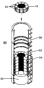
FIGURE 1 is an isometric view of a layer of steel
plates forming a single lamination layer for use in a stator
core;
~ FIGURE 2 is an isometric view of a stator core
module in a module fixture in accordance with the present
invention;
FIGURE 3 is a flow chart of the process of
manufacturing a stator core module in accordance with an
aspect of the present invention; and,
FIGURE 4 is an exploded cut-away view of the
insertion of stator core modules into a stator frame.
DETAILED DESCRIPTION OF A PREFERRED EMBODIMENT
Referring now to the drawings wherein like numerals
indicate like elements throughout, FIGURE 1 depicts an
exemplary stator core plate 20 for use in manufacturing a
stator core in accordance with the present invention. Core
plates 20, stamped from a piece of ferrous material, such as
plate steel are arranged circumferentially to form rings,
e.g_, ring 24. As explained below, each ring 24 constitutes
a single lamination layer in a mufti-layered stator core
module. In the stator core of the present example, nine of
these plates are arranged to form a single ring 24; however,
any suitable number of plates can be shaped and configured for
use in a stator core of any desired diameter without departing
from the scope of the present invention. As is described more
fully below, a mufti-layered laminated stator core module is
formed by stacking multiple rings 24 such that each core plate
20 aligns with the underlying core plate 20 of the prior ring
24 layer.
Referring to FIGURE 2, a module fixture 11 is shown
containing a stack of rings 24, sufficient to make a single
core module. Rings 24 are stacked in module fixture 11 until
the desired height is achieved, forming a core module 10
within module fixture 11. Module fixture 11 is comprised of
a top compression plate 12 and a bottom compression plate 14,
SUBSTITUTE SHEET (RULE 26)
CA 02276102 1999-06-24
WO 98!32211 PCT/US98/0(1354
- 5 -
and precision sleeves 16 disposed at each corner of the the
compression plates 12, 14. Each precision sleeve 16 is a
hollow tube formed of substantially rigid material, such as
steel. The length of each tube is cut to precisely the height
of a completed core module I0. Bolts 17 are disposed through
sleeves 16. Retaining nuts 19 are attached to bolts 17,
holding bolts 17 within sleeves 16, and provide a mechanism
for applying pressure to the set of plates comprising core
module 10 disposed within module fixture 11. During operation
of module fixture 11, a stack of rings (i.e., a module's worth
of rings) is sandwiched between top compression plate 12 and
bottom compression plate 14. As nuts 19 are tightened,
compression plates 12, 14 squeeze the steel plate laminations
tightly together, until compression plates 12, 14 encounter
15 sleeves l6. Module fixture I1 of the present invention can
be adjusted to any desirable core module IO height by
adjusting the fixture for the appropriate number of ring
layers. For example, changing the length of the sleeves 16
and adding additional plates would result in a higher core
20 module 10.
FIGURE 3, presents a flow chart of the process of
manufacturing a core module 10 in accordance with the present
invention. At the initial step (32), steel plates 20 are
arranged in rings 24 and stacked in module fixture 11, as
described in detail with reference to FIGURE 2. Bolts 19 are
then tighten to until sleeves 16 are encountered by
compression plates 12, 14. Core~module 10 is then ready for
Vacuum Pressure Impregnation bonding, according to well-known
industry standards. To that end, in the next step (34),
module fixture 11 containing compressed steel plates 20 is
placed in a vacuum chamber (not shown). The chamber is then
drawn down to about 1 to 2 mm Hg. After the vacuum is at the
appropriate setting, the chamber is flooded with resin (step
. 36). As a result, the resin floods the stack of rings,
entering any gaps between the ring layers. Next (step 38) the
chamber is pressurized, further driving the resin into the
cavities in the stack 10. The component is then removed from
SUBSTITUTE SHEET (RULE 26)
CA 02276102 1999-06-24
WO 98132211 PCTIUS98/00354
_ 6 _
the chamber and placed in an oven (step 40) . The oven is
heated until the resin cures. A complete module core 10 is
then removed from the fixture and is ready for use in
constructing a stator core or stored for later use (step 42).
The resulting module core 10 provides improved heat
conduction, as well as improved operational stability.
Referring now to FIGURE 4, the manufacture of a
stator core from a plurality of core modules 10 is depicted.
As with a conventional stator, stator 60 is comprised of a
stator frame 50 and a stator core 52. However, unlike a
conventional stator, stator 60 is manufactured with core
modules 10, manufactured in accordance with the procedure
described with reference to FIGURE 3. By contrast to some of
the traditional methods of manufacturing a stator, stator core
60 can be assembled directly in the frame 50, obviating the
use of a separate external fixture at the assembly site and
alleviating the need for high pressure stack compression.
Other advantages are obtained by the modular stator core
design. For example, core modules 10 are pre-assembled and
shipped to the final assembly site at the time of stator
assembly. As a result, the modules can be pre-manufactured
off site under better controlled conditions. Moreover, much
lighter duty equipment can be used to lift the core modules
10 into the frame than would otherwise be needed to lift an
entire stator core into the frame. The result of these
advantages is a stator core with improved operational
characteristics, including heat' transfer and relaxation.
Moreover, the final assembly time can be shortened from
several days to as few as a single day.
The stator core assembly is best described with
reference to FIGURE 4. Initially, a stator frame 50 is placed
in an upright position to accept core modules 10. A temporary
assembly base 56 is placed in the bottom of the upright stator
frame during assembly. Base 56 is provided during assembly
to support core modules 10 in the proper position within
stator frame 50. After assembly is complete, base 56 is
removed. After stator frame 50 is prepared for assembly, a
SU8ST1TUTE SHEET (RULE 26)
CA 02276102 1999-06-24
WO 98/32211 PCTIUS98/00354
selected number of core modules 10 are lifted into the stator
frame 50. The number of cores modules selected will vary
' depending on the desired stator length and the selected care
module 10 size. When all of the selected core modules 10 are
' 5 properly positioned in stator frame 50, through bolts (not
shown) are inserted axially through the stator core assembly
via holes 22. The through bolts are then tightened to
complete the stator core assembly. Spring bars 54 are then
tightened to attach the stator core 52 to the stator frame 50.
Stator 60 is then ready for attachment to the turbine (not
shown) .
Those skilled in the art will recognize that other
methods are available to bind the completed stator core
together. For example, disk springs and keys could be
inserted into both ends of the frame locking the modules
together.
Significantly, the processes described above for
manufacturing stator core modules and stators provide
significant manufacturing benefits. For example, core modules
10 can be prefabricated to a standard size in a production
environment, providing all of the quality control benefits
inherent in such an environment. Those core modules can then
be stored or shipped as needed to the location of stator
assembly. Moreover, stators of varying lengths can use the
same core module building blocks. By merely selecting the
number of core modules required for a given stator length and
assembling those core modules into the frame, the stator
manufacturing process can be standardized. Accordingly, the
final stator assembly process involves the assembly of a small
number of core modules; whereas current practice requires the
assembly of thousands of steel plates.
The present invention may be embodied in other
specific forms without departing from the spirit or essential
attributes thereof , for example, the steel plates could be
coted with resin and pressed together to bond the core modules
rather than using Vacuum Pressure Impregnation. Accordingly,
reference should be made to the appended claims, rather than
SUBSTITUTE SHEET (RULE 26)
CA 02276102 1999-06-24
WO 98/32211 PCT/US98/00354
_ g _
to the foregoing specification, as indicating the scope of the
invention.
SU9STtTUTE SHEET (RULE 26)