Sélection de la langue

Search

Sommaire du brevet 2276264 

Énoncé de désistement de responsabilité concernant l'information provenant de tiers

Une partie des informations de ce site Web a été fournie par des sources externes. Le gouvernement du Canada n'assume aucune responsabilité concernant la précision, l'actualité ou la fiabilité des informations fournies par les sources externes. Les utilisateurs qui désirent employer cette information devraient consulter directement la source des informations. Le contenu fourni par les sources externes n'est pas assujetti aux exigences sur les langues officielles, la protection des renseignements personnels et l'accessibilité.

Disponibilité de l'Abrégé et des Revendications

L'apparition de différences dans le texte et l'image des Revendications et de l'Abrégé dépend du moment auquel le document est publié. Les textes des Revendications et de l'Abrégé sont affichés :

  • lorsque la demande peut être examinée par le public;
  • lorsque le brevet est émis (délivrance).
(12) Demande de brevet: (11) CA 2276264
(54) Titre français: ASSEMBLAGE DE DISQUE DE ROUE
(54) Titre anglais: DISK ASSEMBLY
Statut: Réputée abandonnée et au-delà du délai pour le rétablissement - en attente de la réponse à l’avis de communication rejetée
Données bibliographiques
(51) Classification internationale des brevets (CIB):
  • F16D 13/64 (2006.01)
  • F16D 13/72 (2006.01)
  • F16D 13/74 (2006.01)
(72) Inventeurs :
  • KROLL, JURGEN (Allemagne)
  • BASTEL, NORBERT (Allemagne)
(73) Titulaires :
  • BORG-WARNER AUTOMOTIVE GMBH
(71) Demandeurs :
  • BORG-WARNER AUTOMOTIVE GMBH (Allemagne)
(74) Agent: MACRAE & CO.
(74) Co-agent:
(45) Délivré:
(22) Date de dépôt: 1999-06-25
(41) Mise à la disponibilité du public: 2000-01-04
Requête d'examen: 2004-04-28
Licence disponible: S.O.
Cédé au domaine public: S.O.
(25) Langue des documents déposés: Anglais

Traité de coopération en matière de brevets (PCT): Non

(30) Données de priorité de la demande:
Numéro de la demande Pays / territoire Date
19830049.2 (Allemagne) 1998-07-04

Abrégés

Abrégé anglais


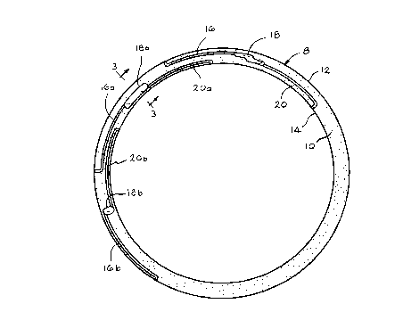
A disk assembly is disclosed. The disk assembly includes a
support member having a circular friction lining mounted on one or both
sides of the support member. An oil channel extends from the outer
edge of the friction lining to the inner edge. The oil channel includes an
enlarged middle oil reservoir section extending through the friction lining.
The inlet section and outlet section of the oil channel are narrow grooves
which are embossed in said friction lining during bonding of the friction
lining.

Revendications

Note : Les revendications sont présentées dans la langue officielle dans laquelle elles ont été soumises.


6
WE CLAIM:
1. An improved disk assembly, comprising a support member
having opposed surfaces, a friction lining mounted adjacent at least one
of said opposed surfaces, said friction lining having outer and inner
edges, an oil channel defined in said friction lining, said oil channel
including an oil inlet section formed in said friction lining, and extending
from such outer edge, a middle section defining a reservoir in
communication with said inlet section, said middle section extending
through said friction lining, and an outlet section, formed in said friction
lining, said outlet section being in communication with said middle
section and extending to said inner edge.
2. A disk assembly, according to claim 1, Wherein said inlet
section and said outlet section are pressed into said friction lining.
3. A disk assembly, according to claim 2, wherein said inlet
section and said outlet section are embossed in said friction lining.
4. A disk assembly, according to claim 2, wherein said middle
section defines an enlarged oil reservoir which is punched out of said
friction lining.
5. A method of making a disk assembly having a support
member and a ring shaped friction lining mounted adjacent at least one
side of the support, comprising the steps of punching a middle oil
reservoir section through the friction lining, bonding said friction lining to

7
said support and during bonding embossing inlet and outlet channels in
the friction lining.

Description

Note : Les descriptions sont présentées dans la langue officielle dans laquelle elles ont été soumises.


CA 02276264 1999-06-25
99069/98035
1
DESCRIPTION
DISK ASSEMBLY
Backaround of the Invention
Disk assemblies are well known in the art and are often used in for
example, clutch assemblies.
One type of disk assembly is a wet-running friction clutch disk
assembly which includes a support an annular friction lining applied to
the support. At least one channel is formed as an oil guide with the
channel extending from the outer edge to the inner edge of the friction
fining. This type of clutch disk assembly for a vehicle clutch is well
known in the art. Often, the grooves are embossed in the friction lining
for defining the oil guiding channels.
The oil passing through such grooves serve to cool the clutch disk
assembly. For efficient cooling, the volume of oil must be sufficient.
The time or flow rate of the oil through the grooves must also be
sufficient. Therefore, it is desirable to have deep grooves and long
grooves. In prior art structures, the groove depth is often up to 50% of
the thickness of the friction lining. Often such grooves can not be
embossed during the production bonding and pressing of the friction
lining. Often, a separate embossing step is required.
Summary of the Invention
The present invention is directed to an improved disk assembly, for
use, for example, in a clutch disk assembly for a wet-running friction
clutch, where the manufacture of the assembly is simple and the
resulting assembly provides efficient oil cooling.
The improved disk assembly includes a support member having
opposed surfaces. A ring shaped friction lining is mounted adjacent at
least one of the opposed surfaces. An oil channel is defined in the
friction lining. The oil channel includes an oil inlet section formed in the

CA 02276264 1999-06-25
99069/98035
2
friction lining; a middle section serving as a reservoir, in communication
with the inlet section, and an outlet section in communication with the
middle section. Preferably, the middle or oil reservoir section extends
completely through the friction lining.
The oil inlet and outlet sections are press formed in the friction
lining, occupying only one part of the friction lining thickness. The oil
inlet section and oil outlet section are preferably embossed in the friction
lining. The middle section or oil reservoir section, is as deep as the
friction lining is thick. Preferably, the middle section is punched out of
the friction lining.
A friction lining may be applied on one or both sides of the support
member. When a friction lining is mounted on both sides, it is often used
as a clutch plate.
The middle section of the oil channel defined by the friction lining
forms a large oil reservoir that ensures a long residua( time for the oil as
it passes through the channel. Effective cooling is achieved by direct
contact with the oil and the metal support member. The oil inlet section
and the oil outlet section may be comparatively flat and narrow. It is
therefore possible to emboss the inlet and outlet sections during bonding
and pressing during the manufacturer of the friction lining. Therefore,
the separate embossing step to form the oil grooves is ordinarily not
required in the present method as opposed to most prior art oii groove
forming methods.
The method of making a clutch assembly, according to the present
invention, where the disk assembly has a support member and a ring
shaped friction lining includes the steps of punching one or more middle
oil reservoir sections through the friction lining. During bonding, the inlet
and outlet channels are pressed or embossed in the friction lining and are
in communication with the middle section. The friction lining is

CA 02276264 1999-06-25
99.069/98035
3
positioned adjacent and is normally adhered to the side of the ring
support.
The clutch disk assembly, according to the present invention, is
preferably used in friction clutches having high friction power. As an
example, a convertor by-pass clutch, designed for prolonged slip
operation can utilize a clutch disk assembly according to the present
invention. The clutch disk assembly of the convertor by-pass clutch
fulfills the function of an oscillation damper during the engine shaft and
gear input shaft when the convertor is by-passed during its slip. Another
example of a preferred use of a clutch disk assembly according to the
present invention is in a starting clutch which is designed for longer slip
operation with a high torque transfer.
Description of the Drawings
Fig. 1 is a plan view of a disk assembly, according to the present
invention, with a plurality of oil channel configurations being shown on
a single friction lining, for illustrative purposes;
Fig. 2 is an enlarged fragmentary perspective view of the disk
assembly shown in Fig. 1; and
Fig. 3 is an enlarged, fragmentary cross-sectional view taken along
the line 3-3 of Fig. 1.
Description of the Preferred Embodiment
An improved disk assembly, according to the present invention, is
generally indicated by the reference number 8. The disk assembly 8
includes a support member 9 and a ring shaped friction lining 10. The
friction lining 10 is normally a circular ring made of a paper-like flat
material, as is well known in the prior art. An oil channel system for
guiding oil extends over somewhat less than the periphery of one
quadrant of the ring shaped friction lining 10 from an outer edge 12 to

CA 02276264 1999-06-25
. 99069/98035
4
an inner edge 14. The oil channel includes an oil inlet section 16, a
middle section 18 and an oil outlet section 20. The oil inlet section 16
and the oil outlet section 20 are pressed, preferably by embossing, in the
friction lining 10. The channel middle section 18, which serves as an
elongated and large oil reservoir is punched through the friction lining 10.
The oil inlet sections 16 and the oil outlet sections 20 are narrow
grooves having a generally rectangular profile. The oil inlet section 16
begins on the outer edge 12 of the friction lining 10 with a radial inlet
opening and then curves 90°. The oil inlet 16 then extends in a
peripheral direction close to the outer edge 12 of the friction lining 10
until it is received by the enlarged oil reservoir middle section 18. The
channel middle section 18 in the present embodiment, is an elongated
offset hole or opening. The form and size of the middle section 18 can
vary. The oil outlet section 20 extends from the middle section 18 in a
peripheral direction turns 90°, and has a radial outlet to the inner
edge.
Referring to Fig. 1, in another embodiment, the middle section 18a
is an elongated, generally elliptical hole or opening 18a. The opening 18a
extends in a generally peripheral direction. In a still further embodiment
a middle section 18b has a hole or opening which is generally elliptical.
The opening 18b extends in a generally radial direction.
As shown in Fig. 1, in the first embodiment, the middle section 18
is stepped in a radial direction with an outer part extending radially
outwardly in a peripheral direction and a connecting inner part extending
radially inward also in a peripheral direction. The inner and outer parts
are in communication with one another forming steps that are offset in
the peripheral direction. The oil inlet section 16 discharges into the outer
part of the middle section 18. The oil outlet section 20 extends
peripherally from the inner part of the middle section 18.
Referring to Fig. 3, the oil inlet section 16 and the oil outlet section
20 are pressed narrow grooves having a rectangular profile. Referring to

CA 02276264 1999-06-25
. 99069/98035
Fig. 3, the narrow, rectangular, oil outlet section 20a receives oil from
the oil reservoir defined by the middle section 18a.
As shown in Fig. 1, the oil inlet section 16 of one overall oil
channel can overlay, for example the oil outlet section 20a of a
5 neighboring channel assembly along the periphery of the channel lining
and vice versus.
In a method of making a disk assembly 8, having the ring shaped
support 9 and the ring shaped friction lining 10, a friction lining 10 is
mounted adjacent at least one side of the support 9. Prior to mounting,
10 the oil reservoir or middle section 18, 18a or 18b is punched through the
friction lining 10. During bonding of the friction lining 10, the inlet
grooves 16, 16a and 16b together with the outlet grooves 20, 20a and
20b are pressed, preferably by embossing into the surface of the friction
lining 10.
Further revisions to the embodiments described above may be
made without departing from the scope of the following claims.

Dessin représentatif
Une figure unique qui représente un dessin illustrant l'invention.
États administratifs

2024-08-01 : Dans le cadre de la transition vers les Brevets de nouvelle génération (BNG), la base de données sur les brevets canadiens (BDBC) contient désormais un Historique d'événement plus détaillé, qui reproduit le Journal des événements de notre nouvelle solution interne.

Veuillez noter que les événements débutant par « Inactive : » se réfèrent à des événements qui ne sont plus utilisés dans notre nouvelle solution interne.

Pour une meilleure compréhension de l'état de la demande ou brevet qui figure sur cette page, la rubrique Mise en garde , et les descriptions de Brevet , Historique d'événement , Taxes périodiques et Historique des paiements devraient être consultées.

Historique d'événement

Description Date
Demande non rétablie avant l'échéance 2007-06-26
Le délai pour l'annulation est expiré 2007-06-26
Réputée abandonnée - omission de répondre à un avis sur les taxes pour le maintien en état 2006-06-27
Inactive : Abandon. - Aucune rép dem par.30(2) Règles 2006-06-05
Inactive : CIB de MCD 2006-03-12
Inactive : Dem. de l'examinateur par.30(2) Règles 2005-12-05
Modification reçue - modification volontaire 2004-06-25
Lettre envoyée 2004-05-12
Modification reçue - modification volontaire 2004-04-28
Requête d'examen reçue 2004-04-28
Toutes les exigences pour l'examen - jugée conforme 2004-04-28
Exigences pour une requête d'examen - jugée conforme 2004-04-28
Lettre envoyée 2000-05-26
Inactive : Transfert individuel 2000-05-04
Inactive : Page couverture publiée 2000-01-04
Demande publiée (accessible au public) 2000-01-04
Inactive : CIB en 1re position 1999-08-23
Inactive : CIB attribuée 1999-08-23
Inactive : Lettre de courtoisie - Preuve 1999-08-10
Inactive : Certificat de dépôt - Sans RE (Anglais) 1999-08-09
Demande reçue - nationale ordinaire 1999-08-06

Historique d'abandonnement

Date d'abandonnement Raison Date de rétablissement
2006-06-27

Taxes périodiques

Le dernier paiement a été reçu le 2005-03-24

Avis : Si le paiement en totalité n'a pas été reçu au plus tard à la date indiquée, une taxe supplémentaire peut être imposée, soit une des taxes suivantes :

  • taxe de rétablissement ;
  • taxe pour paiement en souffrance ; ou
  • taxe additionnelle pour le renversement d'une péremption réputée.

Les taxes sur les brevets sont ajustées au 1er janvier de chaque année. Les montants ci-dessus sont les montants actuels s'ils sont reçus au plus tard le 31 décembre de l'année en cours.
Veuillez vous référer à la page web des taxes sur les brevets de l'OPIC pour voir tous les montants actuels des taxes.

Historique des taxes

Type de taxes Anniversaire Échéance Date payée
Taxe pour le dépôt - générale 1999-06-25
Enregistrement d'un document 2000-05-04
TM (demande, 2e anniv.) - générale 02 2001-06-25 2001-03-29
TM (demande, 3e anniv.) - générale 03 2002-06-25 2002-03-25
TM (demande, 4e anniv.) - générale 04 2003-06-25 2003-03-27
TM (demande, 5e anniv.) - générale 05 2004-06-25 2004-03-29
Requête d'examen - générale 2004-04-28
TM (demande, 6e anniv.) - générale 06 2005-06-27 2005-03-24
Titulaires au dossier

Les titulaires actuels et antérieures au dossier sont affichés en ordre alphabétique.

Titulaires actuels au dossier
BORG-WARNER AUTOMOTIVE GMBH
Titulaires antérieures au dossier
JURGEN KROLL
NORBERT BASTEL
Les propriétaires antérieurs qui ne figurent pas dans la liste des « Propriétaires au dossier » apparaîtront dans d'autres documents au dossier.
Documents

Pour visionner les fichiers sélectionnés, entrer le code reCAPTCHA :


Pour visualiser une image, cliquer sur un lien dans la colonne description du document. Pour télécharger l'image (les images), cliquer l'une ou plusieurs cases à cocher dans la première colonne et ensuite cliquer sur le bouton "Télécharger sélection en format PDF (archive Zip)" ou le bouton "Télécharger sélection (en un fichier PDF fusionné)".

Liste des documents de brevet publiés et non publiés sur la BDBC .

Si vous avez des difficultés à accéder au contenu, veuillez communiquer avec le Centre de services à la clientèle au 1-866-997-1936, ou envoyer un courriel au Centre de service à la clientèle de l'OPIC.


Description du
Document 
Date
(aaaa-mm-jj) 
Nombre de pages   Taille de l'image (Ko) 
Dessin représentatif 2000-01-03 1 10
Description 1999-06-24 5 212
Abrégé 1999-06-24 1 15
Dessins 1999-06-24 2 58
Revendications 1999-06-24 2 42
Certificat de dépôt (anglais) 1999-08-08 1 175
Courtoisie - Certificat d'enregistrement (document(s) connexe(s)) 2000-05-25 1 114
Rappel de taxe de maintien due 2001-02-26 1 112
Rappel - requête d'examen 2004-02-25 1 113
Accusé de réception de la requête d'examen 2004-05-11 1 176
Courtoisie - Lettre d'abandon (taxe de maintien en état) 2006-08-21 1 175
Courtoisie - Lettre d'abandon (R30(2)) 2006-08-13 1 167
Correspondance 1999-08-05 1 14