Note : Les descriptions sont présentées dans la langue officielle dans laquelle elles ont été soumises.
CA 02276404 1999-06-29
WO 9$/29922 _ PCT/US97/22977
1
METHOD FOR INTEGRATING ANTENNAS
IN A DISTRIBUTED ANTENNA SYSTEM
Field of the Invention
The present invention relates generally to transmission systems using
distributed
antennas. More particularly, the present invention is directed to a method and
arrangement
for integrating antennas in a distributed antenna system.
Background of the Invention
Referring now to FIG. 1, an exemplary distributed antenna system is shown.
Such
a system can be used, for example, to distribute wireless carrier signals to
and from remote
locations using a cable television transmission network. The system includes a
central
distribution unit 10 and a plurality of remote RF units 12. The remote units
12 perform RF
signal processing and are associated with radiating elements (antennas) to
propagate the
processed signals. Preferably, the system is designed such that each antenna
provides
efficient coverage to a desired coverage area, without coverage gaps and
without overlapping
(i.e., causing interference) with neighboring coverage areas.
To obtain sufficient antenna gain and coverage area in a typical distributed
antenna
system, an external element such as a monopole or dipole antenna is provided
in each RF
unit. Such external antennas are typically fed by a coaxial cable. Exemplary
remote units
having external antennas 14 are shown in FIGs. 2A-B.
The remote RF units are typically placed in public and/or outdoor locations.
Because
of their locations, environmental factors such as rain, ice, and wind are
important
considerations in the design of a unit. For units located in public areas,
aesthetic
considerations are also important. Because external antennas in conventional
units protrude
from the unit, they are subj ect to severe weather conditions and are
generally regarded as
aesthetically undesirable. Further, dipole and monopole antennas generally
have poor
azimuthal directivity. Therefore, their propagation paths) are not easily
controlled to
provided efficient coverage over a desired area.
Thus, in distributed antenna systems (systems made up of multiple units
connected
to a central combiner), the remote units preferably: a) provide coverage over
a desired area,
CA 02276404 1999-06-29
WO 98/29922 _ PCT/U597122977
2
without coverage gaps or interference with neighboring coverage areas; b) are
weatherproof;
c) are aesthetic; and d) are efficiently integrated.
As described above, known remote units use external dipole or monopole
antennas
connected to coaxial cable. Such remote units meet none of the above criteria.
Accordingly, it would be desirable for a remote unit in a distributed antenna
system
to efficiently provide coverage over a desired coverage area, without coverage
gaps or
interference with neighboring coverage areas.
It would also be desirable for a remote unit to be weatherproof, and for a
remote unit
to take aesthetic considerations into account.
It would also be desirable for a remote unit to have efficiently integrated
antennas.
Summary of the Invention
To overcome the above-noted problems, and provide other advantages, the
present
invention provides for a method and arrangement for integrating multiple
antennas in a
distributed antenna system. According to the method of the present invention,
a plurality of
antennas in a distributed antenna communication system are integrated by
providing a
plurality of antennas on one or more surfaces of a housing. Each antenna is
capable of
providing signal propagation in a desired direction. The plurality of antennas
inside the
housing are integrated by providing one or more internal RF combining
circuits, and one or
more internal RF dividing circuits. Each combining circuit combines signals
received from
two or more of the antennas, and each dividing circuit divides signals to be
propagated from
one signal source into at least two signals for propagation from at least two
antennas.
According to the arrangement of the present invention, an integrated antenna
unit
includes a plurality of antennas provided on one or more surfaces of a
housing. Each
antenna is capable of providing signal propagation in a desired direction. The
arrangement
also includes one or more internal RF combining circuits, and one or more
internal RF
dividing circuits. Each combining circuit combines signals received from two
or more of the
antennas, and each dividing circuit divides signals to be propagated from one
signal source
into at Least two signals for propagation from at least two antennas.
As a result of the method and arrangement according to the present invention,
a
remote unit of a distributed antenna system can be made which provides
efficient coverage
_~__ __.. ...._ _ T. r.r ~......_ _ ~....~~_ _. _ .
CA 02276404 1999-06-29
WO 98/29922 _ PCT/US97/22977
3
over one or more desired areas, is substantially weatherproof, which can be
easily adapted
to desired aesthetic criteria, and in which the antennas are efficiently
integrated.
Brief Description of the Drawings
The features and advantages of the present invention can be understood more
fully
upon reading the following Detailed Description of the Preferred Embodiments
in conjunction
with the accompanying drawings, in which like reference indicia designate like
elements, and
in which:
FIG. 1 is a block diagram of an exemplary distributed antenna system in which
the
present invention can be implemented;
FIGs. 2A-B show conventional rcmote RF units which can be used in the system
of
FIG. 1;
FIG. 3 is a diagram of a remote RF unit, covered by a housing, using an
exemplary
method and arrangement for integrating antennas according to the present
invention;
FIGs. 4A-B are diagrams of the internal combiner and divider circuitry,
respectively,
of the remote RF unit of FIG. 3;
FIGS. SA-B are detailed circuit diagrams showing an exemplary implementation
of
the circuitry of FIGs. 4A-B.
FIGs. 6A-B are diagrams comparing the coverage areas of a conventional
distributed
antenna system with the coverage areas of a system incorporating the method
and
arrangement of the present invention.
Detailed Description of the Preferred Embodiments
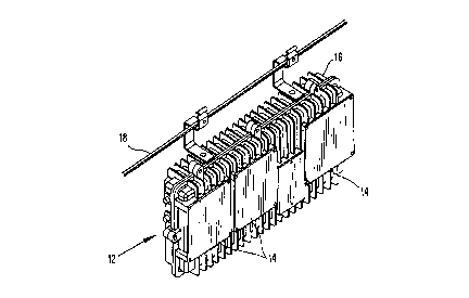
Referring now to FIG. 3, a remote RF unit according to an embodiment of the
present
invention is shown. As shown, the remote RF unit 12 includes multiple
directional patch
antennas 14 mounted on each side of the RF unit 12. The directional patch
antennas 14 each
face a desired direction of signal propagation. The directional patch antennas
can each
provide, e. g. , 5 dBi of gain in the vertical plane. Diversity receive
antennas can be of
opposite polarity (vertical or horizontal), and spatially separated to
decrease correlation. The
remote RF unit 12 is preferably covered with a housing 16. The housing 16 can
be mounted
to a cable television strand 18, as shown, or can be mounted to a telephone
pole, wall, or
CA 02276404 1999-06-29
WO 98/29922 . PCT/US97/22977
4
other structure. According to one embodiment of the present invention, the
housing 16 can
be approximately 9" high by 3" deep by 20" long, and the entire housed unit
can weigh
approximately 12 pounds. The housing can be made of die-cast aluminum which is
powder-
coated, or other suitable materials. The antennas 14 are preferably mounted
substantially
flush with the surfaces of the housing 16. As a result of the flush mounting
of the antennas
14, the antennas can be covered with radomes (radar domes) to provide
environmental
protection and to improve the aesthetic appearance of the unit 12. The
antennas are
integrated, as will be discussed later, to feed the antennas to and from
receiver and
transmitter ports.
The unit 12 is a remote RF unit which can be used in distributed antenna
communication systems. For example, as a remote antenna interface which
extracts a single
PCS (personal communication system) carrier from a downlink CATV network, and
transmits the extracted carrier over an air interface. In the uplink path, the
remote unit 12
receives two diversity instances of a single PCS carrier, converts the
received instances to
different uplink CATV frequencies, and transmits the converted frequencies to
a cable
processor (not shown) over the cable television transmission network.
Referring now to FIGs. 4A-B, a circuit diagram of an exemplary means for
integrating the antennas 14 is shown. Specifically, FIG. 4A shows a diagram of
an
exemplary combiner circuit in which two of the antennas 14 are connected to a
summing
circuit 18. In the circuit of FIG. 4A, the antenna 14 receive signals, the
received signals are
combined in the summing circuit 18, and the output of the summing circuit 18
is provided
to a receiver port 20.
FIG. 4B shows a diagram of an exemplary divider circuit in which the output of
a
transmission port 22 is provided to a divider element 24, and the output of
the divider
element 24 is provided to two of the antennas 14. It will be appreciated that
the combiner
and divider means of FIGs. 4A-B can be modified to allow more than two
antennas to be
combined or divided.
Referring now to FIGs. SA-B, detailed circuit diagrams of exemplary
implementations
of the combiner/splitter circuits of FIGs. 4A-B are shown. The receiver
portion of the
circuit of FIG. SA will now be described. The receiver circuit shown includes
receive
antennas RxA 1, RxA2, RxB 1, and RxB2 for receiving signals, and combiners
100A and
_ ..~.._____ . ..._T. _.~.._._. ___~...
CA 02276404 1999-06-29
WO 98/29922 _ PCT/US97/22977
1008. Combiners 100A and 1008 in this embodiment are Wilkinson combiners. It
will be
appreciated that other suitable passive combiner devices (e.g., quadrature
hybrid, resistive,
etc. ) can be used, depending upon considerations such as power handling,
cost, space, etc.
The outputs of combiners 100A and 1008 are fed to amplifiers 102A and 1028,
respectively,
and filters 104A and 1048, respectively . Filters 104A and 1048 axe, according
to a
preferred embodiment of the present invention, band pass filters having a
bandwidth of
approximately 1850-1910 MHz. The combined, filtered and amplified received
signals are
mixed with oscillator signal Oscl in mixers 106A and 1068 as shown. Oscillator
Oscl is
preferably an oscillator operating at approximately 1580-1640 MHz. The
modulated output
is amplified in amplifiers 108A and 1088.
The outputs of amplifiers 108A and 1088 are filtered in band pass filters 110A
and
1108, respectively. The filters 110A and 1 lOB, according to a preferred
embodiment, have
a bandwidth of approximately 270 MHz. The output of filter 110A is mixed with
oscillator
signal OscS in mixer 112A, and is amplified by variable gain amplifier VGA2.
The output
of filter 1108 is mixed with an oscillator signal Osc6 in modulator 1128, and
is amplified
by variable gain amplifier VGA3. The gain of each of the variable gain
amplifiers is
preferably set based on the received signal strength indication RSSI of the
received signal,
as determined by circuitry not shown. Certain implementations of such a scheme
are
described in the commonly assigned U.S. patent application Serial Number
08/683,187,
"System and Method for Controlling the Level of Signals Output to Transmission
Media in
a Distributed Antenna Network", the entirety of which is incorporated by
reference. The
outputs of variable gain amplifiers 112A and 1128 are combined in combiner 114
and the
combined signal is filtered in low-pass filter 116, and the filtered signal is
supplied to
common cable 118 via combiner/splitter 200. Filter 116 is preferably a filter
which passes
signals below a frequency of approximately 50 MHz. It will be appreciated that
the separate
receive paths for antennas RxA and RxB provide diversity reception.
The transmission portion of the circuit of FIG. SA will now be described. The
signal
to be transmitted is supplied from common cable 118 to combiner/splitter 200.
The
combiner/splitter 200 splits the signal to be transmitted into two signals, a
first signal which
is filtered in band pass filter 202. According to a preferred embodiment of
the present
invention, band pass filter 202 passes signals within a range of approximately
402 to 750
CA 02276404 1999-06-29
WO 98/29922 _ PCT/IJS97/22977
6
MHz.
This signal is mixed with an oscillator signal Osc2 in mixer 204. The
modulated
signal is amplified in amplifier 206, and the amplified signal is filtered in
band pass filter 208
which has, in this example, a bandwidth of approximately 350 MHz. The filtered
signal is
mixed with oscillator signal Osc 1 in mixer 210, amplified by variable gain
amplifier V GA 1
and by amplifier 212. The amplified signal is provided to coupler 214, which
generates a
first signal RF DETECT and a second signal which is supplied to isolator 216.
The first
signal RF detect is used to adjust the gain of variable gain amplifier VGAI.
The isolated
signal is filtered in a low pass filter 218, which passes signals having a
frequency less than,
in this embodiment, approximately 2000 MHz. The filtered signal is split by
sputter 220,
and the split signals are transmitted from antennas TX 1 and TX2. Splitter 220
is, in this
embodiment, a hybrid coupler; however, it will be appreciated that other
suitable devices
(e.g., Wilkinson, quadrature hybrid, resistive, etc.) can be used.
It will be appreciated that in the embodiment of FIG. SA, a standard
transceiver
architecture is used, and the embodiment is therefore economical. In this
embodiment, the
splitter loss occurring at sputter 220 is preferably compensated for by
reducing the budgeted
link margin.
FIG. SB shows an alternative embodiment of the antenna integration circuitry.
In the
embodiment of FIG. SB, each transmitter antenna Txl, Tx2 has a separate
associated
transmitter amplifier chain, and each receive antenna RxA 1, RxA2, RxB 1, and
RxB2 has a
separate associated low noise amplifier 102A 1, 102A2, 102B 1, and 102B2. In
this
embodiment, the transmitter splitting occurs at a point in the transmission
path where the loss
due to splitting can be compensated for by the amplifiers VGA 1 and 212A and
212B.
Further, the reception combining occurs at a point in the reception path where
the loss due
to combining can be compensated by appropriate selection or adjustment of the
to«~ noise
amplifiers 102A 1-102B2. This embodiment allows higher performance than the
embodiment
of FIG. SA, but is generally more expensive and complex.
It will be appreciated that FIGs. SA-B show two embodiments of circuitry for
integrating antennas, and that the circuit components shown and described may
be modified
as necessary depending upon design considerations such as power handling
capability, cost,
space, etc.
~~..... _ __
CA 02276404 1999-06-29
WO 98/29922 _ PCT/LTS97/22977
7
Referring now to FIGs. 6A-B, a comparison of the coverage areas of a
conventional
distributed antenna system and a distributed antenna using the method and
arrangement of
the present invention is shown. In FIG. 6A, a suburban application of a
distributed antenna
system is shown in which omnidirectional remote RF antennas 12a and 12b are
used.
Omnidirectional remote RF antenna 12a provides coverage to houses S4a and 54d,
arid
omnidirectional antenna 12b provides coverage to houses 54c and 54f. However,
because
antennas 12a and 12b are omnidirectional, the coverage provided to houses 54b
and 54e is
subject to interference. This does not provide efficient coverage over the
desired area. In
contrast, the use of directional antennas 12a' and 12b' is shown in FIG. 5B.
The directional
antennas allows coverage to be provided to the houses 54a-f without
interference, thus
covering the desired area in a more efficient manner.
While the foregoing description includes many details and specificities, it is
to be
understood that these details and specificities are for purposes of
illustration and explanation
only. Many modifications can be made to the disclosed embodiments which do not
depart
from the spirit and scope of the invention, as defined by the following claims
and their legal
equivalents.