Note : Les descriptions sont présentées dans la langue officielle dans laquelle elles ont été soumises.
CA 02277906 1999-07-12
DESCRIPTION
COIN PROCESSING DEVICE
TECHNICAL FIELD
This invention relates to a coin processing device, used in automatic
vending machines, money changing machines and service equipment, etc., that
sorts and holds inserted coins by denomination and that pays out the sorted
and
held coins as change, and more particularly, to improvements in coin
accommodating means for temporarily holding sorted genuine coins by
denomination.
BACKGROUND ART
Conventional automatic vending machines, money changing machines, and
service equipment, etc., have been equipped with coin processing devices that
sort and hold inserted coins by denomination and pay out sorted and held coins
as
change.
Fig. 3 is a schematic perspective view of a conventional coin processing
device 1.
The coin processing device 1 comprises the following two main
constituting elements.
The first constituting element comprises coin sorting means 3 that sorts
inserted coins by genuine and counterfeit and then the genuine coins by
denomination. The coin sorting means 3 is mounted in the upper part of a
device body 2 having a roughly IZ-shaped cross-section and constituting the
frame of the coin processing device 1 in such manner that it can be freely
mounted and removed.
CA 02277906 1999-07-12
The second constituting element comprises coin dispensing means 9 that
stores the sorted genuine coins by denomination and that sorts and pays out
the
stored genuine coins according to the change amount. The coin dispensing
means 9 is located in the lower portion of the device body 2, and comprises
four
coin tubes 5, 6, 7, and 8 having different diameters except in part, which are
lined
up in a row.
These four coin tubes 5, 6, 7, and 8 are loaded inside the device body 2 so
that they can be freely loaded and unloaded. Of these four, coin tubes 5, 6
and 7
are positioned directly below the coin sorting means 3 when they are loaded
into
the device body 2. The coin tube 8, is a supplemental tube wherein coins that
are used with particularly high frequency are stored beforehand, the diameter
of
which is set to be the same as that of the coin tube 6.
Reference number 10 in Fig. 3 is a control switch group (inventory switch
group) for giving directions such as a payment direction when forcing the
payment of certain denominations of the coins stored in the coin dispensing
means 9 for each denomination. The control switch group 10 is positioned
inside a switch box 11 provided at the upper right of the device body 2.
By means of such a coin processing device 1, coins first pass through a
coin insertion hopper 12 into the coin sorting means 3 where they are sorted
according to genuine and counterfeit and according to the denomination of the
genuine coins. Of these coins, the genuine coins are sorted and stored in the
coin tubes 5, 6 and 7 constituting the coin dispensing means 9.
When the denominations of the change are specified, the coins stored in
the coin tubes 5, 6, 7 and 8 are selected and paid out according to the change
amount.
The conventional coin processing device 1 described above, however, is
loaded in the limited space inside an automatic vending machine or other
2
CA 02277906 1999-07-12
equipment. Therefore, the overall size thereof is strictly specified
beforehand.
In particular, as indicated in the enlarged perspective cross-sectional view
of the
coin tubes 5, 6, 7 and 8 constituting the coin dispensing means 9 and device
body
2 in Fig. 4, the width L of the device body 2 is strictly specified.
When, on the other hand, the coin processing device 1 described above is
used in countries wherein different numbers of coin denominations having
different diameters are used, it becomes particularly necessary to employ a
larger
number of the coin tubes that are lined up to constitute the coin dispensing
means
9.
However, the coin tubes 5, 6, 7 and 8 that are lined up together to
constitute the conventional coin dispensing means 9 are arranged in a
configuration wherein the line A that connects the axial centers a, b, c and d
of
the coin tubes 5, 6, 7 and 8, forms a straight line, as depicted in the top
view in
Fig. 5. Therefore, when another coin tube 11 having a still different diameter
is
lined up so that the line B that connects the axial centers a, b, c, d and a
forms a
straight line, the overall width L 1 of the coin tubes S, 6, 7, 8 and 11 will
be larger
than the width L of the device body 2 (i.e. L1 > L). Therefore, the coin tubes
5,
6, 7, 8 and 11 cannot be accommodated inside the device body 2. This presents
a problem.
Reference number 12 in Figs. 4 to 6 is a control board positioned on the
back side of the coin tubes 5, 6, 7 and 8 inside the device body 2. On the
control board 12 are mounted not only electronic components for controlling
the
drives of various kinds of electronic equipment (such as solenoid plungers,
etc.,
for driving coin sorting levers) located inside either the coin sorting means
3 or
coin dispensing means 9, as described above, but also, as depicted in Figs. 5
and
6, empty sensors 20, 21, 22, 23 and 24 for detecting whether or not coins are
presently stored in the coin tubes 5, 6, 7, 8 and 11.
3
CA 02277906 2001-10-03
These empty sensors 20,21,22,23 and 24 comprise electromagnetic coil
proximity switches that detect whether or not any coins are being held in the
coin tubes 5,6,7,8 and 11 by detecting changes in inductance. However, the
distances Dl, D2, D3, D4 and D5 between the inner walls of the coin tubes
5,6,7,8 and 11 and the corresponding empty sensors 20,21,22,23 and 24,
respectively, differ from one another. Therefore, there is a danger of
variation
developing in the sensitivities with which the presence of coins in the coin
tubes is detected by the corresponding empty sensors 20,21,22,23 and 24, if no
sensitivity adjustments are made. In order to compensate for this, sensitivity
adjustments are made beforehand so that the sensitivities with which the
presence of coins is detected by the empty sensors 20, 21, 22, 23 and 24 are
equalized.
Accordingly, an object of the present invention is to provide a coin
processing device wherein many coin tubes can be accommodated within a
specific width.
DISCLOSURE OF THE INVENTION
In a broad aspect, the present invention relates to a coin processing
device comprising: a device body; coin sorting means for determining whether
inserted coins are genuine or counterfeit, and for sorting genuine coins by
denomination; coin accommodating means for holding the sorted genuine coins
4
CA 02277906 2001-10-03
by denomination; coin dispensing means for selecting and paying out the
genuine
coins held in the coin accommodating means according to change amounts; the
coin sorting means, the coin accommodating means and the coin dispensing
means being provided in the device body; the coin accommodating means
comprising a plurality of integrally formed coin tubes that constitute a coin
tube
group provided in the device body in such a manner as to be freely loaded onto
and unloaded from the device body, and the plurality of coin tubes being
disposed
so that a line connecting axial centers thereof forms a zigzag line as seen
from
above; wherein a control board is provided in the device body at a position of
back side of the coin tube group; a plurality of electromagnetic coil
proximity
switches for detecting presence and absence of genuine coins stored in the
coin
tubes are provided at positions corresponding to the coin tubes along a
straight
line as seen from above; and when the coin tube group is loaded in the device
body, the coin tubes of the coin tube group are disposed so that distances
between
the closest portions of inner walls of the coin tubes from corresponding
proximity
switches and the corresponding proximity switches are the same as each other.
With this configuration, even when the number of coin tubes that constitute
the coin dispensing means is increased, it is possible to maximally suppress
an
expansion in the total width of the coin tubes, thus making it possible to
4(a)
CA 02277906 1999-07-12
accommodate many coin tubes within the device body of a given width.
Further, because it is possible to accommodate many coin tubes within the
device body of a given width, when coin tubes are installed inside the device
body in accord with the number of coins used and the different diameters in
each
country's coinage, it is possible to install a plurality of coin tubes,
corresponding
to each country, inside main apparatus bodies of the same scale, without
altering
the size of the device body.
BRIEF DESCRIPTION OF THE DRAWITTGS
Fig. 1 is a schematic cross-sectional view of a coin processing device in a
first embodiment of the present invention;
Fig. 2 is a schematic cross-sectional view of a coin processing device in a
second embodiment of the present invention;
Fig. 3 is a schematic perspective view of a conventional coin processing
device;
Fig. 4 is a schematic perspective cross-sectional view of a conventional
coin processing device;
Fig. 5 is a schematic cross-sectional view of a conventional coin
processing device; and
Fig. 6 is a schematic cross-sectional view of a conventional coin
processing device wherein the number of coin tubes has been increased by one.
BEST MODE FOR CARRYING OUT THE INVENTION
The attached drawings are now used in describing the present invention in
greater detail
Detailed descriptions are given below of embodiments of the coin
processing device according to the present invention.
5
- CA 02277906 1999-07-12
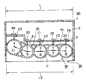
Fig. 1 is a cross-sectional view of a coin processing device 30 in a first
embodiment of the present invention, wherein parts that are the same as those
in
Figs. 5 and 6 are designated by identical symbols.
In the coin processing device 30 in the first embodiment, five coin tubes 5,
6, 7, 8 and 11 are integrally formed, and are positioned, as seen from the
top, so
that a line C connecting the axial centers a, b, c, d and a thereof forms a
line that
bends to the right and to the left, that is to say, forms a zigzag line. In
particular,
the line extending from the axial center a of the coin tube 5 positioned on
the left
side of the drawing and connecting the axial center a of the coin tube 11 of
maximum diameter positioned at the extreme left adjacent to the coin tube 5
bends sharply in the clockwise direction.
The plurality of coin tubes 5, 6, 7, 8 and 11 lined up so that the line C
connecting the axial centers a, b, c, d and a thereof forms a zigzag line, as
seen
from above, constitute coin accommodating means 34 that can store a greater
variety of genuine coins, by denomination, within a certain width L. The coin
accommodating means 34 constitutes coin dispensing means 39 that holds sorted
genuine coins by denomination and selects and pays out held genuine coins
according to change amounts.
Thus, in the coin processing device 30 of the first embodiment, the coin
dispensing means 39 is designed so as to comprise coin accommodating means
34 made up of coin tubes 5, 6, 7, 8 and 11 lined up so that the line C
connecting
their axial centers a, b, c, d and a forms a zigzag line, as seen from above.
Therefore, the widths between adjacent coin tubes, in the coin tubes 5, 6, 7,
8 and
11, are narrowed, and the total width L2 of the coin tubes 5, 6, 7, 8 and 11
is
formed so as to be narrower than the total width L1 of the conventional coin
tubes 5, 6, 7, 8 and 11, as depicted in Fig. 6 (i. e. L2 < L 1 ). As a
consequence,
the total width L2 of the coin tubes 5, 6, 7, 8 and 11 arranged such that the
line C
6
CA 02277906 1999-07-12
connecting the axial centers a, b, c, d and a thereof forms a zigzag line, as
depicted in Fig. 1, can be set equal to or less than the width L of the device
body
2 (i.e. L2 5 L), making it possible to install the five coin tubes 5, 6, 7, 8
and 11
inside the device body 2.
In other words, in the coin processing device 30 of the first embodiment,
the coin dispensing means 39 comprises the coin accommodating means 34, and
the coin accommodating means 34 comprises the coin tubes 5, 6, 7, 8 and 11
lined up so that the line C connecting the axial centers a, b, c, d and a
thereof
forms a zigzag line, as seen from above. Therefore, even when the number of
coin tubes used is increased from the conventional four tubes to five, as
depicted
in Fig. 1, the expansion of the total width L2 of the coin tubes 5, 6, 7, 8
and 11
can be suppressed. It is therefore possible to accommodate the five coin tubes
5,
6, 7, 8 and 11 inside the device body 2 having a given width L.
In the coin processing device 30 of the first embodiment, furthermore,
although five coin tubes 5, 6, 7, 8 and 11 are accommodated inside the device
body 2 of given width L, even when the number of coin tubes used is increased
above five, it is possible to suppress the expansion of the total width L2 of
the
coin tubes loaded inside the device body 2, by the coin accommodating means 34
of the above configuration. Thus, many coin tubes can be accommodated inside
a device body 2 of given width L.
Accordingly, with the coin processing device 30 represented in the first
embodiment of the present invention, when coin tubes are installed in the
device
body 2 according to the coinage of various countries wherein the number of
coins
used and the diameters thereof differ, it is possible to install a plurality
of coin
tubes, corresponding to each country, in main apparatus bodies 2 of the same
scale, without altering the size of the device body 2.
When the coin dispensing means 39 comprises coin accommodating means
7
CA 02277906 1999-07-12
34 made up of coin tubes 5, 6, 7, 8 and 11 lined up so that the line C
connecting
their axial centers a, b, c, d and a forms a zigzag line, as seen from above,
as in
the coin processing device 30 in the first embodiment, the distances E1, E2,
E3
and E4 between the inner walls of the coin tubes 5, 6, 7 and 8 and the empty
sensors 20, 21, 22 and 23 that detect the presence of genuine coins inside the
coin
tubes 5, 6, 7 and 8 can be made the same (i.e., E1 = E2 = E3 = E4).
The empty sensors 20, 21, 22 and 23 are positioned on a control board 31
corresponding to the coin tubes 5, 6, 7 and 8, respectively, and the control
board
31 is installed in the device body 2 positioned in back of the coin tubes 5,
6, 7
and 8.
More specifically, when a plurality of coin tubes of differing diameters are
lined up, these tubes are arranged so that the line connecting their axial
centers a,
b, c, d and a does not coincide with a straight line, but, instead, the line C
connecting their axial centers a, b, c, d and a forms a zigzag line, as
depicted in
Fig. 1. With this configuration, the coin tubes 5, 6, 7 and 8 can be
integrally
formed, with the distances from the back surfaces of the coin tubes 5, 6, 7
and 8
to the inner walls of the coin tubes 5, 6, 7 and 8 made to be equal. In other
words, it is possible to make the distances E1, E2, E3 and E4 between the
inner
walls of the coin tubes 5, 6, 7 and 8 and the corresponding empty sensors 20,
21,
22 and 23 disposed on the control board 31 positioned in parallel relative to
the
back surfaces of the coin tubes 5, 6, 7 and 8, respectively, the same
distance. It
therefore becomes possible to reduce occurrences of variation in the
sensitivity
with which the presence of coins held in the coin tubes 5, 6, 7 and 8 is
detected
by the empty sensors 20, 21, 22 and 23 due to the variation of distance
between
the inner walls of these coin tubes and the respective empty sensors.
In the coin processing device 30 of the first embodiment, five coin tubes 5,
6, 7, 8 and 11 are accommodated in a device body 2 of given width L. However,
8
CA 02277906 1999-07-12
as noted akeady, with the coin processing device of the present invention, the
coin accommodating means comprising a plurality of coin tubes, according to
the
numbers and disparate diameters of coins used by different countries, can be
installed inside main apparatus bodies 2 of the same scale, without altering
the
size of the device body 2. For example, in order to conform to the coinage of
different countries, coin tubes having inner diameters differing from those of
the
coin tubes 5, 6, 7, 8 and 11 depicted in Fig. 1 can be loaded in the device
body 2,
as depicted in Fig. 2, wherein parts that are the same as those in Fig. 1 are
identified by the same symbol.
The coin processing device 50 depicted in Fig. 2 is a coin processing
device in a second embodiment of the present invention, wherein, according to
the coinage of another country wherein the diameters are different, coin tubes
5',
6', 7', 8' and 11' having inner diameters differing from those of the coin
tubes 5, 6,
7, 8 and 11 in Fig. 1 are loaded into a device body 2.
In the coin processing device 50 in the second embodiment, five coin tubes
5', 6', 7', 8' and 11', integrally formed, are lined up in an arrangement
wherein a
line D connecting the axial centers a', b', c', d' and e' of the coin tubes
5', 6', 7', 8'
and 11', respectively, is a line that bends to the right and to the left, that
is, forms
a zigzag line.
Furthermore, the plurality of coin tubes 5', 6', 7', 8' and 11', lined up so
that
the line D connecting their axial centers a', b', c', d' and e' forms a zigzag
line, as
seen from above, constitutes coin accommodating means 54 that accommodates
an even greater variety of genuine coins, by denomination, within a given
width
L. The coin accommodating means 54 constitutes coin dispensing means 59
that holds the sorted genuine coins by denomination and that pays out the held
genuine coins according to change amounts.
In the coin processing device 50 in the second embodiment, with the coin
9
CA 02277906 1999-07-12
accommodating means 54, the distances E'1, E'2, E'3 and E'4 between the inner
walls of the coin tubes 5', 6', 7' and 8' and corresponding empty sensors 20,
21, 22
and 23, respectively, can be made the same (i.e., E'1 = E'2 = E'3 = E'4), and
the
distances E'1, E'2, E'3 and E'4 can be made the same distance as the distances
El,
E2, E3 and E4 between the inner walls of the coin tubes 5, 6, 7 and 8 and the
empty sensors 20, 21, 22 and 23 depicted in Fig. 1 (i.e., E1 = E2 = E3 = E4 =
E'1
= E'2 = E'3 = E'4). Therefore, even when coin tubes 5', 6', 7' and 8' having
diameters different from those of the coin tubes 5, 6, 7 and 8 are loaded into
the
same device body 2, in coping with the coinage of various countries, no
variation
will develop in the sensitivity wherewith the empty sensors 20, 21, 22 and 23
detect the presence of coins in the corresponding coin tubes 5', 6', 7' and
8'.
Therefore, the presence of coins held inside the corresponding coin tubes 5',
6', 7'
and 8' can be detected reliably.
It is possible, furthermore, to set the distance ES between the inner wall of
the coin tube 11 and the empty sensor 24 depicted in Fig. 1 to be the same as
the
distance E'S between the inner wall of the coin tube 11' and the empty sensor
24
depicted in Fig. 2 (i.e. so that ES = E'S). Therefore, no variance will
develop in
the sensitivity wherewith the empty sensor 24 detects the presence of coins
held
in the corresponding coin tubes 11 and 11', respectively. Therefore, even when
coin tubes 5', 6', 7', 8' and 11' having diameters made different from those
of the
coin tubes 5, 6, 7, 8 and 11 are employed, it becomes possible to stably
detect the
presence of coins held inside the corresponding coin tubes 5', 6', 7', 8' and
11'.
With the coin dispensing means 59 that is provided with coin
accommodating means 54, the total width I,3 of the coin tubes 5', 6', 7', 8'
and 11'
can be set so as to be equal to or less than the width of the device body 2
(i.e. so
that L3 _< L).
Also, although not indicated in the drawings, when a coin tube group 3 5
CA 02277906 1999-07-12
wherein the coin tubes 5, 6, 7, 8 and 11 are integrally formed, or a coin
group 55
wherein the coin tubes 5', 6', 7', 8' and 11' are integrally formed, is loaded
inside
the device body 2, identification means for identifying the type of coin tube
group, that is, means for identifying whether the coin tube group loaded is of
the
type of the coin tube group 35 depicted in Fig. l, or of the coin tube group
55
depicted in Fig. 2, or of some other coin tube group different from either the
coin
tube group 35 or the coin tube group 55, are provided in the control board 31
indicated in Figs. l and 2.
Such other type of coin tube group might be, for example, a coin tube
group comprising coin tubes having diameters differing from those of the coin
tubes described in the foregoing, or a coin tube group wherein some number of
coin tubes other than five is integrally formed.
The identification means may comprise a cassette identification sensor (not
shown) constituted, for example, with three linked switches provided in the
control board 31 and projections (not shown) projecting from the back surface
of
the coin tube groups 35 and 55 that depress one or other of the three linked
switches.
In the case of such a cassette identification sensor, when the coin tube
group 35 is loaded in the device body 2 depicted in Fig. 1, the projection
could
activate the uppermost of the three linked switches, whereas when the coin
tube
group 55 is loaded in the device body 2, the middle switch of the three linked
switches could be activated. Thus, by varying the position where the
projection
is formed in the respective types of coin tube group, it would be easy to
detect
which type of coin tube group has been loaded in the device body 2, thereby
making it possible to automatically switch the control of the sorting
functions,
etc., based on detection signals therefrom, so as to accord with the coins
stored in
each type of coin tube group.
11
CA 02277906 1999-07-12
With the coin processing devices 30 and 50 in the first and second
embodiments, respectively, the coin tube groups have five coin tubes lined up
therein, but the number of such coin tubes is not limited thereto, and may be
made whatever number will accord with the number of coins used and the
diameters thereof, depending on the country.
INDUSTRIAL APPLICABILITY
The coin processing device according to the present invention, as described
in the foregoing, is useful for applications vi automatic vending machines,
money
changing machines and service equipment, etc., as a coin processing device for
sorting and storing the inserted coins by denomination, and paying out the
sorted
and stored coins as change, and is particularly well suited for use as a coin
processing device wherewith many coin tubes can be accommodated within a
given width.
12