Sélection de la langue

Search

Sommaire du brevet 2281257 

Énoncé de désistement de responsabilité concernant l'information provenant de tiers

Une partie des informations de ce site Web a été fournie par des sources externes. Le gouvernement du Canada n'assume aucune responsabilité concernant la précision, l'actualité ou la fiabilité des informations fournies par les sources externes. Les utilisateurs qui désirent employer cette information devraient consulter directement la source des informations. Le contenu fourni par les sources externes n'est pas assujetti aux exigences sur les langues officielles, la protection des renseignements personnels et l'accessibilité.

Disponibilité de l'Abrégé et des Revendications

L'apparition de différences dans le texte et l'image des Revendications et de l'Abrégé dépend du moment auquel le document est publié. Les textes des Revendications et de l'Abrégé sont affichés :

  • lorsque la demande peut être examinée par le public;
  • lorsque le brevet est émis (délivrance).
(12) Brevet: (11) CA 2281257
(54) Titre français: RATEAU TIREUR A CADRE SIMPLE
(54) Titre anglais: SINGLE FRAME PULL RAKE
Statut: Durée expirée - au-delà du délai suivant l'octroi
Données bibliographiques
(51) Classification internationale des brevets (CIB):
  • A01D 78/00 (2006.01)
  • A01D 78/14 (2006.01)
  • A01D 80/00 (2006.01)
(72) Inventeurs :
  • ROWSE, DAN D. (Etats-Unis d'Amérique)
  • ROWSE, RON A. (Etats-Unis d'Amérique)
(73) Titulaires :
  • DAN D. ROWSE
  • RON A. ROWSE
(71) Demandeurs :
  • DAN D. ROWSE (Etats-Unis d'Amérique)
  • RON A. ROWSE (Etats-Unis d'Amérique)
(74) Agent: SMART & BIGGAR LP
(74) Co-agent:
(45) Délivré: 2003-12-30
(22) Date de dépôt: 1999-09-01
(41) Mise à la disponibilité du public: 2001-02-16
Requête d'examen: 2001-02-15
Licence disponible: S.O.
Cédé au domaine public: S.O.
(25) Langue des documents déposés: Anglais

Traité de coopération en matière de brevets (PCT): Non

(30) Données de priorité de la demande:
Numéro de la demande Pays / territoire Date
09/374,968 (Etats-Unis d'Amérique) 1999-08-16

Abrégés

Abrégé français

La ligne de traction d'un appareil moteur s'étend le long d'un ensemble de languette raccordé de manière pivotante à un ensemble de cadre de râteau à roues et croise l'extrémité d'évacuation arrière de l'ensemble de cadre lorsque le râteau est à son angle d'attaque maximal et avec l'axe longitudinal étendu lorsque l'angle d'attaque est à son minimum, équilibrant ainsi les forces sur le râteau et minimisant la dérive de râteau de sorte qu'une largeur régulière de matière coupée puisse être ratissée.


Abrégé anglais

The line of pull from a prime mover extends along a tongue assembly pivotally connected to a wheel rake frame assembly and intersects with the rear discharge end of the frame assembly when the rake is at its maximum angle of attack and with the extended longitudinal axis when the angle of attack is at its minimum thereby balancing forces on the rake and minimizing rake drift such that a consistent width of cut material can be raked.

Revendications

Note : Les revendications sont présentées dans la langue officielle dans laquelle elles ont été soumises.


CLAIMS:
1. A pull type rake for windrowing cut material comprising,
a frame assembly with a raking means having a longitudinal axis,
said frame assembly being pivotally connected to a tongue
assembly for moving the frame assembly between transport and
field positions and when in said field position varying the
width of the cut material being windrowed by varying the angle
between the longitudinal axis of the frame assembly with said
raking means and the tongue member,
said frame assembly with rake means having forward and rearward
ends, said rearward end being freely moveable as said frame
assembly with rake means pivots relative to said tongue
assembly, and
said tongue assembly having a forward end adapted to be connected
to a prime mover and a rear end pivotally connected to said
frame assembly establishing a line of pull through said
forward and ?-ear connections varying from extending through
the rear end of said frame assembly with said rake means to
extending through the extended longitudinal axis of said frame
assembly with said rake means extended rearwardly of said
frame assembly with said rake means rear end for minimizing
drift of said frame assembly with said rake means when in said
field position.
2. The rake of Claire 1 wherein a hydraulic cylinder is
provided for pivoting said frame assembly relative to said
tongue assembly.
3. The rake of Claim 2 wherein said frame includes a
plurality of ground support wheels along its length.
6

4. The rake of Claim 3 wherein one of said ground support
wheels is positioned at the rear end of said frame assembly
and is steerable to vary the angle between the longitudinal
axis of said frame assembly and said tongue assembly.
5. The rake of Claim 4 wherein said steerable wheel has a
pivot axis and the line of pull extends through or close to
said pivot axis when said frame assembly is in said field
position.
6. The rake of Claim 5 wherein said steerable wheel
includes a hydraulic cylinder for pivoting said wheel about
its pivot axis.
7. The rake of Claim 6 wherein said raking means includes
rake wheels rotatably mounted on arms pivotably connected to
said frame assembly along its substantial length.
8. The rake of Claim 5 wherein the line of pull extends
through or close to the pivot axis of said tongue assembly
pivotally connected to said frame assembly.
9. The rake of Claim 1 wherein said frame assembly when in
said transport position the forward end thereof is connected
by a brace member extending to said tongue assembly.
10. The rake of Claim 1 wherein said frame assembly includes
a rear main frame and a bridge frame portion which extends
from said rear main frame over said rake means and terminates
in a forward frame member parallel to said rear main frame to
which said tongue assembly is pivotally connected.
7

11. The rake of Claim 10 wherein said forward frame member
includes opposite forward and rearward ends with said
rearward end having a ground support wheel and the forward
end being pivotally connected by a hydraulic cylinder to said
tongue assembly for varying the angle between said raking
means and said tongue assembly.
8

Description

Note : Les descriptions sont présentées dans la langue officielle dans laquelle elles ont été soumises.

CA 02281257 1999-09-O1
INVENTORS: Dan D. Rowse and Ron A. Rowse
TITLE: SINGLE FRAME PULL RAKE
BACKGROUND OF THE INVENTION
The present day single frame pull rake having rake
wheels along the longitudinal axis of the frame will have a
line of pull from the prime mover through the rake frame
generally centered between the opposite ends of the rake
frame. The problem with this arrangement is that the forces
generated by the cut material moving along the length of the
rake from the rake's forward end to the rearward discharge
end increase and thus tend to reduce the rake's angle of
attack. What is needed to overcome this problem is a rake
having tongue and frame assemblies with a steerable support
wheel. that will balance the forces on the frame assembly such
that a consistent angle of attack will be maintained.
SUMMARY OF THE INVENTION
A tongue assembly is hydraulically pivoted to a frame
assembly having a steerable support wheel at its rear cut
material discharge end with the line of pull from a prime
mover extending substantially through the pivot axis between
the tongue assembly and frame assembly and the pivot axis of
the steerable rear wheel. Changing the angle of attach of
the rake will vary the point at which the line of pull
intersects with the rake frame varying between the discharge
end at the steerable wheel of the rake to a point on the
frame assembly extended rearwardly when the angle of attack
is reduced.
1

CA 02281257 1999-09-O1
DESCRIPTION OF THE DRAWINGS
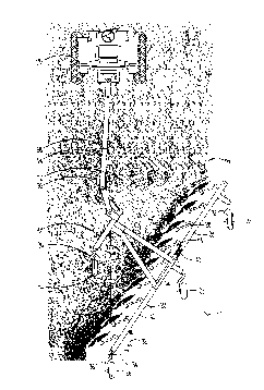
Figure 1 is a top plan view of the wheel rake of this
invention in field operation showing the cut material being
moved along the rake wheels from the forward end to the rear
S discharge end.
Figure 2 is a top plan view of the rake main frame and
rake wheels of a typical prior art rake wherein the line of
pull from the tractor to the rake frame is generally centered
between the rake frame opposite ends allowing the cut
l0 material forces on the rake rear discharge end to cause the
rake to drift to a position shown by the rake frame in dashed
lines involving a reduced angle of attack.
Figure 3 is a view similar to figure 2 but illustrating
the rake of this invention wherein the line of pull is
15 through the rear discharge end of the rake thereby allowing
the rake to maintain a fixed angle of attack.
Figure 4 is a top plan view of the rake in a transport
position.
Figure 5 is a front perspective view of the rake.
20 Figure 6 is a top plan view thereof showing the typical
maximum angle of attack represented by the angle A. An
alternate embodiment of the steerable rear end support wheel
is shown.
Figure 7 is a view similar to figure 6 but showing a
25 reduced angle of attack represented by the angle B and
showing the line of pull intersecting with the longitudinal
axis of the rake extended rearwardly.
2

CA 02281257 1999-09-O1
DESCRIPTION OF THE PREFERRED EMBODIMENTS
The wheel rake of this invention is referred to
generally in figure 6 by the reference numeral 10 as seen
being pulled by a prime mover 12.
The rake 10 includes a tongue assembly 14 pivotally
connected about an axis 16 to a frame assembly 18 having a
series of rake wheels 20 along the length of a rear main
frame 22. The main frame 22 has a forward end 24 and a
trailing rear end 26 where a steering support wheel 28 is
positioned for pivoting about a vertical axis 30 in response
to a hydraulic cylinder 32 extending between the main frame
22 and a bracket 34 rigidly connected to a wheel shank 36.
The main frame 22 includes a forward frame portion 38
connected by a hinge 40 to a rear frame portion 42.
The frame assembly 18 includes in addition to the rear
frame 22 a bridge frame portion 44 which extends from the
rear frame portion 42 over the rake wheels 20 and terminates
in a forward frame member 46 connected to the tongue assembly
14 through a clevice 48 for pivotable movement about the
pivot axis 16. The forward frame member 46 has a rear end 50
to which a ground support wheel 52 is pivotally connected.
An opposite forward end 54 of the forward frame member 46 is
connected by a hydraulic cylinder 58 to the tongue assembly
14 .
As seen in figure 5 the bridge frame portion 44 includes
rear frame legs 60 rigidly connected to the rear frame
portion 42 of the rear main frame 22. A "V" shaped
horizontal frame portion 62 extends over the rake wheels 20
and engages a forward vertical frame leg 64 which in turn
rigidly engages the forward cross frame member 46. As
further seen in figure 5 the tongue assembly 14 includes a
3

CA 02281257 1999-09-O1
forward tongue member 66 connected through a hinge 68 to a
rear tongue member 70 having a support wheel 72.
In figure 4 the rake 10 is in a transport position with
the forward end 24 of the forward frame portion 38 being
locked by a brace to the forward tongue member 66 by the
brace 74 engaging a pin 78.
In operation, it is seen in figure 6 that a maximum
angle of attack A of approximately 55° establishes a line of
pull 80 through the pivot axis 30 of the steerable support
l0 wheel 28 and also through the pivot axis 16 between the
tongue assembly 14 and the frame assembly 18. In figure 7,
however, the minimum angle of attack B of approximately 35°
causes the line of pull 80 to intersect an extended
longitudinal axis 82 of the rear main frame 22. Thus, it is
seen that the width of the material 84 as seen in figure 1
being raked will remain constant as the line of pull is
through the center of the maximum opposing force applied to
the rake when the angle of attack is at its greatest as seen
in figure 6 and when the angle of attack is reduced as seen
in figure 7 the forces on the rake frame at its discharge end
are reduced, minimizing the problem and easily allowing the
steerable wheel 28 to maintain a consistent course.
The angle of attack may be varied by operation of the
power cylinder 58 pivotally interconnecting the tongue
assembly 14 to the frame assembly 18 and the power cylinder
32 connected to the steering support wheel 28 will be
operated as appropriate to maintain the desired angle of
attack.
In figure 7 it is seen that the steerable wheel 28 and
its pivot axis 30 have been moved from the rear discharge end
of the main frame 22 rearwardly such that the wheel 28 and
4

CA 02281257 1999-09-O1
its mounting to the main frame 22 does not interfere with
storage of the wheel rake 10.

Dessin représentatif
Une figure unique qui représente un dessin illustrant l'invention.
États administratifs

2024-08-01 : Dans le cadre de la transition vers les Brevets de nouvelle génération (BNG), la base de données sur les brevets canadiens (BDBC) contient désormais un Historique d'événement plus détaillé, qui reproduit le Journal des événements de notre nouvelle solution interne.

Veuillez noter que les événements débutant par « Inactive : » se réfèrent à des événements qui ne sont plus utilisés dans notre nouvelle solution interne.

Pour une meilleure compréhension de l'état de la demande ou brevet qui figure sur cette page, la rubrique Mise en garde , et les descriptions de Brevet , Historique d'événement , Taxes périodiques et Historique des paiements devraient être consultées.

Historique d'événement

Description Date
Représentant commun nommé 2019-10-30
Inactive : Périmé (brevet - nouvelle loi) 2019-09-03
Requête pour le changement d'adresse ou de mode de correspondance reçue 2018-01-12
Accordé par délivrance 2003-12-30
Inactive : Page couverture publiée 2003-12-29
Inactive : Grandeur de l'entité changée 2003-10-28
Préoctroi 2003-10-14
Inactive : Taxe finale reçue 2003-10-14
Un avis d'acceptation est envoyé 2003-06-03
Lettre envoyée 2003-06-03
Un avis d'acceptation est envoyé 2003-06-03
Inactive : Approuvée aux fins d'acceptation (AFA) 2003-05-21
Modification reçue - modification volontaire 2003-04-25
Inactive : Dem. de l'examinateur par.30(2) Règles 2003-04-24
Modification reçue - modification volontaire 2003-03-21
Inactive : Dem. de l'examinateur par.30(2) Règles 2003-03-05
Modification reçue - modification volontaire 2001-05-25
Lettre envoyée 2001-03-01
Demande publiée (accessible au public) 2001-02-16
Requête d'examen reçue 2001-02-15
Exigences pour une requête d'examen - jugée conforme 2001-02-15
Toutes les exigences pour l'examen - jugée conforme 2001-02-15
Inactive : Page couverture publiée 2001-02-15
Inactive : CIB attribuée 1999-10-08
Inactive : CIB en 1re position 1999-10-08
Inactive : Certificat de dépôt - Sans RE (Anglais) 1999-09-23
Demande reçue - nationale ordinaire 1999-09-22

Historique d'abandonnement

Il n'y a pas d'historique d'abandonnement

Taxes périodiques

Le dernier paiement a été reçu le 2003-08-22

Avis : Si le paiement en totalité n'a pas été reçu au plus tard à la date indiquée, une taxe supplémentaire peut être imposée, soit une des taxes suivantes :

  • taxe de rétablissement ;
  • taxe pour paiement en souffrance ; ou
  • taxe additionnelle pour le renversement d'une péremption réputée.

Les taxes sur les brevets sont ajustées au 1er janvier de chaque année. Les montants ci-dessus sont les montants actuels s'ils sont reçus au plus tard le 31 décembre de l'année en cours.
Veuillez vous référer à la page web des taxes sur les brevets de l'OPIC pour voir tous les montants actuels des taxes.

Titulaires au dossier

Les titulaires actuels et antérieures au dossier sont affichés en ordre alphabétique.

Titulaires actuels au dossier
DAN D. ROWSE
RON A. ROWSE
Titulaires antérieures au dossier
S.O.
Les propriétaires antérieurs qui ne figurent pas dans la liste des « Propriétaires au dossier » apparaîtront dans d'autres documents au dossier.
Documents

Pour visionner les fichiers sélectionnés, entrer le code reCAPTCHA :


Pour visualiser une image, cliquer sur un lien dans la colonne description du document. Pour télécharger l'image (les images), cliquer l'une ou plusieurs cases à cocher dans la première colonne et ensuite cliquer sur le bouton "Télécharger sélection en format PDF (archive Zip)" ou le bouton "Télécharger sélection (en un fichier PDF fusionné)".

Liste des documents de brevet publiés et non publiés sur la BDBC .

Si vous avez des difficultés à accéder au contenu, veuillez communiquer avec le Centre de services à la clientèle au 1-866-997-1936, ou envoyer un courriel au Centre de service à la clientèle de l'OPIC.


Description du
Document 
Date
(aaaa-mm-jj) 
Nombre de pages   Taille de l'image (Ko) 
Dessin représentatif 2001-02-06 1 84
Revendications 2003-03-20 3 87
Revendications 2003-04-24 3 90
Revendications 2001-05-24 3 81
Abrégé 1999-08-31 1 14
Description 1999-08-31 5 167
Dessins 1999-08-31 6 351
Revendications 1999-08-31 3 79
Certificat de dépôt (anglais) 1999-09-22 1 175
Accusé de réception de la requête d'examen 2001-02-28 1 179
Rappel de taxe de maintien due 2001-05-01 1 111
Avis du commissaire - Demande jugée acceptable 2003-06-02 1 160
Taxes 2003-08-21 1 31
Correspondance 2003-10-13 1 32
Taxes 2002-08-14 1 32
Taxes 2001-08-19 1 32