Sélection de la langue

Search

Sommaire du brevet 2282077 

Énoncé de désistement de responsabilité concernant l'information provenant de tiers

Une partie des informations de ce site Web a été fournie par des sources externes. Le gouvernement du Canada n'assume aucune responsabilité concernant la précision, l'actualité ou la fiabilité des informations fournies par les sources externes. Les utilisateurs qui désirent employer cette information devraient consulter directement la source des informations. Le contenu fourni par les sources externes n'est pas assujetti aux exigences sur les langues officielles, la protection des renseignements personnels et l'accessibilité.

Disponibilité de l'Abrégé et des Revendications

L'apparition de différences dans le texte et l'image des Revendications et de l'Abrégé dépend du moment auquel le document est publié. Les textes des Revendications et de l'Abrégé sont affichés :

  • lorsque la demande peut être examinée par le public;
  • lorsque le brevet est émis (délivrance).
(12) Demande de brevet: (11) CA 2282077
(54) Titre français: PRESENTOIR A DOUILLES
(54) Titre anglais: SOCKET DISPLAYING DEVICE
Statut: Réputée abandonnée et au-delà du délai pour le rétablissement - en attente de la réponse à l’avis de communication rejetée
Données bibliographiques
Abrégés

Abrégé anglais


A socket displaying device includes a back plate 10 with two grooves
defined in two sides thereof and a stop 141 extends from the first end of the
back plate. A frame 20 is slidably engaged with the two grooves of the back
plate and has two side plates 21 between which a plurality of chambers 23 are
defined so as to receive sockets 30. Each of the side plates has a flange 211
extending toward the other side plate. The frame has a first end thereof so as
to
engage with the stop of the back plate when the frame is in its first
position. An
aperture 26 is defined in the second end of the frame so that when the frame
is
pulled away from the back plate, the stop is engaged with the aperture so
limit
the frame from dropping from the back plate.

Revendications

Note : Les revendications sont présentées dans la langue officielle dans laquelle elles ont été soumises.


6
WHAT IS CLAIMED IS:
1. A socket displaying device comprising:
a back plate having two grooves defined in two sides thereof and a
stop extending from the first end of said back plate, and
a frame having two rails on two sides thereof and two side plates
extending from said frame, said two rails slidably engaged with said grooves
of
said back plate, a plurality of boards connected between said two side plates,
each of said side plates having a flange extending toward the other side
plate,
said frame having a first end which is engaged with said stop when said frame
is
located in a first position, an aperture defined in the second end of said
frame so
as to engage with said stop when said frame is located in a second position.
2. The socket displaying device as claimed in claim 1, wherein each
board has two bosses respectively extending from two surfaces thereof.
3. The socket displaying device as claimed in claim 1, wherein said
back plate has a hole defined through the second end thereof and said hole is
in
alignment with said aperture of said frame.
4. The socket displaying device as claimed in claim 1, wherein said
back plate has a leading plate extending from the second end thereof, said
leading plate having a slot defined therethrough.
5. The socket displaying device as claimed in claim 1, wherein said
back said frame has a recess defined in the first end thereof and said recess
is
located in opposite to said two side plate sides.

Description

Note : Les descriptions sont présentées dans la langue officielle dans laquelle elles ont été soumises.

CA 02282077 1999-09-10
2
SOCKET DISPLAYING DEVICE
FIELD OF THE INVENTION
The present invention relates to a socket receiving and displaying
device which includes a back plate and a frame which is slidably connected to
the back plate and has a plurality of receiving chambers in each of which a
socket is received.
BACKGROUND OF THE INVENTION
A conventional socket receiving and displaying device generally
includes a box-like member for a socket or sockets to be received therein, and
a
1o card which is connected to the box and has a hole defined therein. The card
is
hung on a wall and the box member is made of transparent material so that the
customers can see the socket that he/she wants to buy. Nevertheless, the
displaying device is no more than a package when the customers buy the
sockets home so that the displaying device will be discarded. The users put
the
sockets into a socket receiving or.retaining device which is suitable to be
carried
with the users. In other words, the displaying device cannot meet the needs of
the users who needs a displaying device which can be carried with him/her so
that the users do not need to purchase sockets receiving device suitable to be
carried with the users.
2o The present invention intends to provide a socket displaying device
which has a strong structural strength and the sockets can be seen directly.
The
displaying device is suitable to be carried and used as a general tool
receiving
rack.
SUMMARY OF THE INVENTION
In accordance with one aspect of the present invention, there is
provided a socket displaying device comprising a back plate having two
grooves defined in two sides thereof and a stop extending from the first end
of

CA 02282077 1999-09-10
3
the back plate. A frame has two rails on two sides thereof so as to slidably
engaged with the two grooves of the back plate. Two side plates extend from
the
frame and a plurality of boards are connected between the two side plates so
as
to define a plurality of chambers for receiving sockets therein. Each of the
side
plates has a flange extending toward the other side plate. The frame has a
first
end which is engaged with the stop when the frame is in its first position. An
aperture is defined in the second end of the frame so as to engage with the
stop
when the frame is in its second position.
The primary object of the present invention is to provide a socket
to displaying device which can be used as a tool rack which is easily carried
by the
users.
Another object of the present invention is to provide a socket
displaying device which has a frame in which sockets are received, and a back
plate relative to which the frame is slidably engaged.
These and further objects, features and advantages of the present
invention will become more obvious from the following description when taken
in connection with the accompanying drawings which show, for purposes of
illustration only, several embodiments in accordance with the present
invention.
BR1FF nFSCrRIPTION OF THF nRAWINC~S
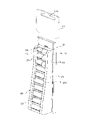
Fig. 1 is a perspective view of the socket displaying device in
accordance with the present invention;
Fig. 2 is a perspective view of the back plate of the socket displaying
device in accordance with the present invention;
Fig. 3 is an exploded view of the frame in accordance with the present
invention and the sockets to be received in the frame;

CA 02282077 1999-09-10
4
Fig. 4 is an end illustrative view to show the frame is engaged with the
back plate
Fig. 5 is a perspective view of the socket displaying device in
accordance with the present invention with sockets received in the frame of
the
device and the frame is located in its first position;
Fig. 6 is a perspective view of the socket displaying device in
accordance with the present invention wherein the frame is located in its
second
position, and
Fig. 7 is a perspective view of the socket displaying device in
1o accordance with the present invention wherein a tie strip extends through
the
hole and the aperture so secure the frame to the back plate.
Referring to Figs. 1 to 4, the socket displaying device in accordance
with the present invention comprises a back plate 10 having a rectangular
frame
12 and a plurality of protrusions 13 extending from two sides of the
rectangular
frame 12 so as to define two grooves. A plate 14 is connected to the first end
of
the back plate 10 and a stop 141 extends from the distal end of the plate 14.
A
leading plate 11 extends from the second end of the back plate 10. The leading
plate 11 has a slot 111 defined therethrough so that the back plate 10 can be
2o hung on a wall. A hole 15 is defined through the second end of the back
plate
10.
A frame 20 has two rails 24 on two sides thereof so as to be slidably
engaged with the grooves of the back plate 10. Two side plates 21 extend from
the frame 20 and a plurality of boards 22 are connected between the two side
plates 21 so as to define a plurality of chambers 23 in each of which a socket
30
can be received, Each board 22 has two bosses 221 respectively extending from
two surfaces thereof so that the socket 30 is inserted into the chamber
between

CA 02282077 1999-09-10
two boards 22 by force-fitting the socket 30 over the two bosses 221. Each of
the side plates 21 has a flange 211 extending toward the other side plate 21
so
that the socket 30 will not drop between the two side plates 21. The frame 20
has a recess 27 defined in the first end thereof and the recess 27 is located
in
5 opposite to the two side plate sides 21. Therefore, when the frame 20 is
moved
relative to the back plate 10, the stop 141 can pass through the recess 27.
Therefore, as shown in Fig, 5, the first end of the frame 20 is engaged
with the stop 141 when the frame 20 is located in a first position. An
aperture
26 is defined in the second end of the frame 20 so as to engage with the stop
l0 141 when the frame is located in a second position as shown in Fig. 6.
Referring
to Fig. 7, it is to be noted that when the frame 20 is in its first position,
the hole
is in alignment with the aperture 26 of the frame 20 so that a tie strip 40
may
extend through the hole 15 in the back plate 10 and the aperture 26 in the
frame
so as to secure the frame 20 to the back plate 10.
15 The socket displaying device of the present invention can be displayed
in a hardware store and the sockets 30 can be seen touched via the two side
plates 22 of the frame 20. The device can also be used as a tool rack and is
easily carried with the users. The sockets 30 are easily taken from or
inserted
into the frame 20 by pulling the frame 20 relative to the back plate 10 to the
2o position where the desired chamber 23 is accessible.
While we have shown and described various embodiments in
accordance with the present invention, it should be clear to those skilled in
the
art that further embodiments may be made without departing from the scope
and spirit of the present invention.

Dessin représentatif
Une figure unique qui représente un dessin illustrant l'invention.
États administratifs

2024-08-01 : Dans le cadre de la transition vers les Brevets de nouvelle génération (BNG), la base de données sur les brevets canadiens (BDBC) contient désormais un Historique d'événement plus détaillé, qui reproduit le Journal des événements de notre nouvelle solution interne.

Veuillez noter que les événements débutant par « Inactive : » se réfèrent à des événements qui ne sont plus utilisés dans notre nouvelle solution interne.

Pour une meilleure compréhension de l'état de la demande ou brevet qui figure sur cette page, la rubrique Mise en garde , et les descriptions de Brevet , Historique d'événement , Taxes périodiques et Historique des paiements devraient être consultées.

Historique d'événement

Description Date
Le délai pour l'annulation est expiré 2002-09-10
Demande non rétablie avant l'échéance 2002-09-10
Réputée abandonnée - omission de répondre à un avis sur les taxes pour le maintien en état 2001-09-10
Demande publiée (accessible au public) 2001-03-10
Inactive : Page couverture publiée 2001-03-09
Inactive : CIB attribuée 1999-10-27
Inactive : CIB en 1re position 1999-10-27
Inactive : Certificat de dépôt - RE (Anglais) 1999-09-30
Demande reçue - nationale ordinaire 1999-09-29
Toutes les exigences pour l'examen - jugée conforme 1999-09-10
Exigences pour une requête d'examen - jugée conforme 1999-09-10

Historique d'abandonnement

Date d'abandonnement Raison Date de rétablissement
2001-09-10

Historique des taxes

Type de taxes Anniversaire Échéance Date payée
Requête d'examen - petite 1999-09-10
Taxe pour le dépôt - petite 1999-09-10
Titulaires au dossier

Les titulaires actuels et antérieures au dossier sont affichés en ordre alphabétique.

Titulaires actuels au dossier
JACK LEE
Titulaires antérieures au dossier
S.O.
Les propriétaires antérieurs qui ne figurent pas dans la liste des « Propriétaires au dossier » apparaîtront dans d'autres documents au dossier.
Documents

Pour visionner les fichiers sélectionnés, entrer le code reCAPTCHA :


Pour visualiser une image, cliquer sur un lien dans la colonne description du document. Pour télécharger l'image (les images), cliquer l'une ou plusieurs cases à cocher dans la première colonne et ensuite cliquer sur le bouton "Télécharger sélection en format PDF (archive Zip)" ou le bouton "Télécharger sélection (en un fichier PDF fusionné)".

Liste des documents de brevet publiés et non publiés sur la BDBC .

Si vous avez des difficultés à accéder au contenu, veuillez communiquer avec le Centre de services à la clientèle au 1-866-997-1936, ou envoyer un courriel au Centre de service à la clientèle de l'OPIC.


Description du
Document 
Date
(aaaa-mm-jj) 
Nombre de pages   Taille de l'image (Ko) 
Dessin représentatif 2001-02-15 1 11
Revendications 1999-09-09 1 40
Abrégé 1999-09-09 1 22
Dessins 1999-09-09 7 102
Description 1999-09-09 4 184
Certificat de dépôt (anglais) 1999-09-29 1 175
Rappel de taxe de maintien due 2001-05-13 1 111
Courtoisie - Lettre d'abandon (taxe de maintien en état) 2001-10-08 1 185