Note : Les descriptions sont présentées dans la langue officielle dans laquelle elles ont été soumises.
CA 02282838 1999-09-20
1427-3
METHOD AND APPARATUS FOR PROCESSING LARGE SQUARE
HAY BALES INTO SMALLER RECOMPRESSED BALES
Field of Invention
This invention relates to compressed forage products, and in
particular, to a method of processing large square bales of hay
into smaller, recompressed bales.
Background of the Invention
There is a growing international market for recompressed hay,
particularly in Japan and other Asian rim countries. Freight is
one of the biggest costs in exporting, hay overseas. Shipping is
usually done in containers, which have a maximum weight limit.
Freight is based on the number of containers, and so to minimize
freight the container must be loaded to the maximum weight
allowable. A typical hay bale, which consists of loose field hay
which has been compressed once and strapped to form a bale, is
too bulky to be transported overseas economically. Therefore, hay
bales are commonly recompressed into smaller, denser bales before
shipping.
Traditional recompression techniques were limited to small hay
bales (approximately 35 to 40 kg; 16-18 in x 16 in x 48 in), e.g.
U.S. Patent 5,249,350. However, balers which produce large
square bales (approximately 750 kg; and with approximate
dimension of 48 in x 52 in x 96 in) , have become increasingly
popular, due to the increased efficiency of bale production. In
particular, large square bales cost less in materials and man
hours to produce, and are more efficiently handled and
transported across land to export packaging facilities. These
1
CA 02282838 2007-07-16
large square bales must be processed into smaller, denser bales
before shipping, to reduce the costs of freight. It is also
important that the bales be processed into smaller, more
manageable units, because end users in Asian rim countries._,
generally lack the necessary equipment to handle large, heavy
bales. Accordingly, there is a need for a method of processing
large square bales into a product that maximizes container
weight, yet is light enough to be readily handled by the end
user, without automated equipment.
Suumary of the Invention
Accordingly, it is an object of the present invention to provide
an improved method and apparatus for processing a large square
hay bale into recompressed units.
This object is achieved by providing a method of processing a
large square hay bale, into recompressed units comprising the
steps of:
(a) making at least one cut through said bale to produce at
least two slabs of approximately equal size;
(b) separating said slabs;
(c) recompressing said slabs in a compression chamber; and
(d) removing said slabs from the compression chamber;
wherein
(i) the bale has a plurality of binding straps;
(ii) in step (a) the cut is made between at least two of
the straps in a direction substantially parallel to the
direction of the straps; and
(iii) in step (a) said cut is made by pushing the bale
through at least one stationary horizontal knife.
2
CA 02282838 2007-07-16
Conveniently, the bale has a plurality of binding straps, and
the cut is made between at least two of the straps in a
direction substantially parallel to the direction of the straps.
Conveniently, the cut is made by pushing the blade through at
least one stationary horizontal knife using a hydraulically
actuated plate.
Preferably, the slabs are separated by elevating the slabs using
elevator means having a platform which is movable between a down
position, wherein it receives the slabs of the bale, and an up
position, where it is substantially level with a bale support,
and pushing the slabs one at a time from the elevator means onto
the bale support, using a moving means or pusher.
Coriveniently, the separated slabs are moved along the bale
support to a compression chamber, wherein the slabs may be
compressed using a hydraulic compression ram.
In one embodiment, a selected amount of the slab is cut prior to
introduction into the compression chamber. Conveniently, the
selected amount may be determined by weight.
Preferably, a plurality of spaced apart straps are affixed to
the recompressed units. In one embodiment of the present
method, at least one cut is made through the recompressed unit
after strapping to produce at least two smaller units of
approximately equal size, wherein the cut(s) are made between
the straps in a direction substantially parallel to the
direction of the straps. Conveniently, the cut(s) are made by
pushing the recompressed unit through at least one stationary
vertical knife.
3
CA 02282838 2007-07-16
In one embodiment, the smaller units are lowered to the floor
using a second elevator means, and pushing onto the floor using
a moving means. The invention also seeks to provide an apparatus for
processing
a large square hay bale into recompressed units, comprising in
combination:
a first cutting means for making at least one cut through
the bale to produce at least two slabs of approximately equal
size, said first cutting means comprising:
a bale bed of sufficient size to accommodate the hay bale,
having
(i) a cutting end which is adjacent to said
separating means;
(ii) at least one stationary horizontal knife,
situated at the cutting end of the bale bed, to create
slabs of approximately equal size;
(iii) means for supporting said at least one
stationary horizontal knife; and
a separating means for separating the slabs, adjacent to
said first cutting means;
a bale support means, adjacent to said separating means;
a compression chamber for recompressing the slabs, adjacent
to said bale support means;
a first moving means for moving the slabs along the bale
support means and into the compression chamber, wherein the
slabs may be compressed to form recompressed units;
a second moving means for moving the recompressed units out
of the compression chamber; and
a third moving means for pushing the bale through said at
least one stationary horizontal knife, to produce said slabs.
4
CA 02282838 2007-07-16
An advantage of this method is that it efficiently processes a
large square bale into smaller, denser bales, which are more
cost-effective for overseas transport, and which may be more
easily handled by end-users without automated equipment. A
further advantage of this method is that it produces multiple
recompressed bales with each cycle of the recompression chamber,
which allows for greater efficiency of production. A still
further advantage of this method is that it produces
recompressed bales of uniform weight and good appearance.
Brief Description of the Dravings
A better understanding of the invention will be obtained by
considering the detailed description below, with reference to
the following drawings of embodiments of the present invention
in which:
FIGS. lA to lE are perspective views showing the processing of a
large square hay bale using the apparatus of this invention.
FIG. 1A illustrates the step of making two horizontal cuts in
the large square bale, to create three horizontal slabs.
FIG. 1B illustrates the step of making a vertical cut in the
slab, to section off a unit having a desired weight.
4a
CA 02282838 1999-09-20
Figure 1C illustrates the unit, before recompression.
Figure 1D illustrates the step of recompressing and strapping the
unit.
Figure 1E illustrates the step of cutting the recompressed unit
into the desired end products, having the desired weights.
Figures 2A to 2E are perspective views showing an alternative
embodiment of the present invention, for processing a large
square bale of different dimension than that illustrated in
Figures 1A to 1E.
Figure 2A illustrates the step of making one horizontal cut in
the large square bale, to create two horizontal slabs.
Figure 2B illustrates the step of making a vertical cut in the
slab, to section off a unit having a desired weight.
Figure 2C illustrates the unit, before recompression.
Figure 2D illustrates the step of recompressing and strapping the
unit.
Figure 2E illustrates the step of cutting the recompressed unit
into the desired end products, having the desired weights.
Figure 3 is a top plan view of the apparatus.
Figure 4 is a side view of another section of the apparatus
wherein a bale is forced against a stationary horizontal knife.
CA 02282838 1999-09-20
Figure 5 is a front view of a vertical knife for use in the
apparatus.
Figure 6 is a schematic front view of an elevator; and
Figure 7 is a cross-sectional view of a compactor of the
embodiment taken along the line 7-7 of Figure 3.
Detailed Description of the Invention
Referring to Figures 1A to 1E and 2A to 2E, a method for
processing a large square hay bale 21 according to the present
invention comprises the following steps. At least one horizontal
cut 20 is made through the bale to produce slabs 22 of
approximately equal size. A typical large square bale has a
plurality of binding straps, and the cut 20 is made between
straps in a direction substantially parallel to the direction of
the straps. The slabs 22 are then separated from each other and
moved along a bale support towards a compression chamber. A
vertical cut 24 is made through a slab 22 to produce a unit 22a
of a desired weight to fill the compression chamber. The unit
22a is compressed in the compression chamber to provide a
compressed unit 26, removed from the compression chamber, and
strapped using a plurality of straps 28 in a spaced apart
relationship, such that a vertical cut 30 may be made between the
straps 28 to produce an end product 32 of a desired weight.
It will be appreciated that the present method is suitable for
large square bales of various sizes, and may also be used for
processing smaller bales, with appropriate adjustments to the
number of cuts. For example, in Figures 1A to 1E, a large square
bale having the dimensions of 96 in x 52 in x 48 in, is processed
by making two horizontal cuts 20 through the hay bale to produce
6
CA 02282838 1999-09-20
three slabs 22 of approximately equal size. A vertical cut 24 is
made through a slab 22 to produce a unit 22a having a desired
weight. After compression and strapping, two vertical cuts 30
are made through the compressed unit 26 to produce an end product
32 having approximate dimensions of 16 in x 17.5 in x 18 in.
In another embodiment, shown in Figures 2A to 2E, a large square
bale having the dimensions of 96 in x 36 in x 36 in, is processed
by making one horizontal cut 20 through the hay bale to produce
two slabs 22 of approximately equal size. A vertical cut 24 is
made through a slab 22 to produce a unit 22a of a desired weight
to fill the compression chamber. After compression and
strapping, one vertical cut 30 is made through the compressed
unit 26 to produce an end product 32 having approximate
dimensions of 16 in x 18 in x 18 in.
It will be appreciated that one may vary the weight of the end
product 32 by adjusting the weight of the unit 22a used to fill
the compression chamber and / or the number of vertical cuts 30
made to the compressed unit 26.
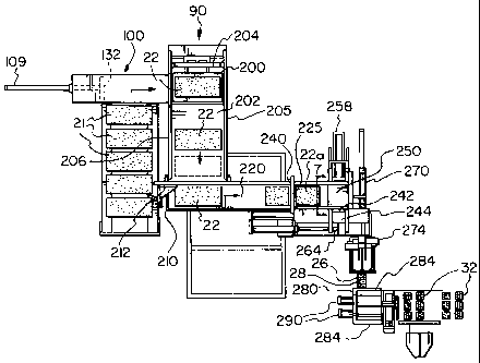
An apparatus for carrying out the method is shown generally at 90
in Figure 3 and includes a bale cutter shown at 100 in Figure 4.
As shown in Figure 4 a bale 21 is moved into contact with
stationary knives 105. Knife attachment members 101 are secured
as by welding to opposed side knife support members 103 adjacent
one end of a bale bed 102.
Each of the knives 105 has a flat side 106, a bevelled side 107
and a cutting edge 108. The knives 105 are spaced apart to
define three approximately equal compartments having a top edge
7
CA 02282838 1999-09-20
equipped with a pressure plate 115 secured to the side plates
103.
In an alte'rnate embodiment, the cutting device may have only one
horizontal knife or multiple horizontal knives.
A cylinder 109 mounted on a pivot 119 at an end of the bale bed
102 remote from the knives 105 has an inner end secured to the
side of a ram head 132. The ram head 132 has upright
transversely extending pusher plates 124, 125 and 126 secured
thereto as by welding. Spaces 133 and 134 are provided at the
ends of the plate 125, and are in alignment with the knives 105
and a space at the outer end of the plate 124 accommodates the
pressure plate 115.
In operation, a bale 21 is placed on the bale bed 102 and the
hydraulic cylinder 109 actuated thereby forcing a bale 21 against
the cuttiiig edge 108 of the knives 105. The upper side of the
bale 21 contacts the pressure plate 115 to minimize deformation
of the bale 21. The knives 105 can extend into the spaces 133
and 134 to complete the cutting of a bale 21 into three slabs 22
which are received on an elevator platform separating device 200.
The elevator platform 200 (as shown more clearly in Figure 6)
moves between a down position, where it is in alignment with the
bale bed 102, and an up position, where it is in alignment with
a bale support 202, and is indexed to stop as each of the slabs
22 is in alignment with the bale support 202. A pusher 204 is
then activated as one of the slabs 22 is aligned with the bale
support 202 and off loads an upper one of the slabs 22 onto the
bale support 202. The pusher 204 moves upwardly and rearwardly
before descending for the next cycle.
8
CA 02282838 1999-09-20
As shown in Figure 3, the bale support 202 is provided with
vertical sides 205 and 206 to guide the slab 22. The bale
support 202 has a right angle bend at 210 and a pusher 212,
similar to pusher 204, engages an end of a slab 22 to move the
slab towards a weigh station 220 and a second cutting knife 225.
Figure 5 shows a preferred embodiment of part of the invention 90
in which knife guide members 221 are attached, by welding or
similar conventional means, to opposed sides 205 and 206 of the
bale support 202. Cross member 223 is similarly attached to the
upper ends 224 of the knife guide members 221. The knife 225 has
a flat side (not shown) and a bevelled side 227 meeting at a
cutting edge 228, and is mounted on cutting hydraulic cylinders
229 by means of clevises 230 so as to be slidably engaged in
guide channels 231. Cutting channel 222 accommodates the knife
cutting edge 228 when the knife 225 is in the lowered position.
Referring again to Figure 3, another pusher means 240, similar to
the pusher 204, is preferably provided to move cut slab 22a in
front of inlet opening 242 of the compression chamber 244. As
shown more clearly in Figure 7 the compression chamber 244 is
provided with guide means 250 hingedly attached at the compactor
inlet 242. The guide means has a top wall 252 and two side walls
254 and 256. It will be appreciated that the guide means 250 is
raised before the cut slab 22a is moved to the compression
chamber 244. When the cut slab 22a is in position, the guide
means 250 is lowered and a rectangular ram provided with suitable
hydraulic means 258 is adapted to move the cut slab 22a into the
compression chamber 244. The major portion of the compaction or
compression is provided by a hydraulically operated ram 264 which
moves parallel to the table 202. A compressed unit 26 is ejected
by an ejection ram 270 and is positioned in a banding or
9
CA 02282838 1999-09-20
strapping station. The bale strapping machine 274 moves along
the length of the recompressed unit 26 providing straps 28 at the
required intervals. The recompressed unit 26 is not capable of
being easily handled without machinery and therefor further
subdividing of the recompressed unit 26 is carried out in the
cutter box 280. A ramp may be sloped downwardly from the
strapping machine 274 to the cutter box 280 to feed the
recompressed units 26 into the cutter box 280. The cutter box
280 is positioned to receive recompressed units 26 leaving the
strapping station 274 and has walls 284 to guide the recompressed
units 26 as hydraulic rams 290 move the bale slab through at
least one vertical knife which divides the recompressed unit 26
into smal-ler units 32 of approximately equal size. In a
preferred embodiment, the cutter box 280 contains two vertical
knives. The vertical cuts are made between the straps in a
direction substantially parallel to the direction of the straps.
A second elevator receives the smaller units 32 after they pass
through vertical knives, and lowers them to the ground, where a
moving device pushes the smaller units 32 from the second
elevator onto the ground.