Sélection de la langue

Search

Sommaire du brevet 2290838 

Énoncé de désistement de responsabilité concernant l'information provenant de tiers

Une partie des informations de ce site Web a été fournie par des sources externes. Le gouvernement du Canada n'assume aucune responsabilité concernant la précision, l'actualité ou la fiabilité des informations fournies par les sources externes. Les utilisateurs qui désirent employer cette information devraient consulter directement la source des informations. Le contenu fourni par les sources externes n'est pas assujetti aux exigences sur les langues officielles, la protection des renseignements personnels et l'accessibilité.

Disponibilité de l'Abrégé et des Revendications

L'apparition de différences dans le texte et l'image des Revendications et de l'Abrégé dépend du moment auquel le document est publié. Les textes des Revendications et de l'Abrégé sont affichés :

  • lorsque la demande peut être examinée par le public;
  • lorsque le brevet est émis (délivrance).
(12) Demande de brevet: (11) CA 2290838
(54) Titre français: LAMPE ELECTRIQUE
(54) Titre anglais: ELECTRIC LAMP
Statut: Réputée abandonnée et au-delà du délai pour le rétablissement - en attente de la réponse à l’avis de communication rejetée
Données bibliographiques
(51) Classification internationale des brevets (CIB):
  • H01K 01/46 (2006.01)
  • H01J 05/48 (2006.01)
  • H01K 07/06 (2006.01)
(72) Inventeurs :
  • HELBIG, PETER (Allemagne)
  • ECKHARDT, FRITZ (Allemagne)
(73) Titulaires :
  • PATENT-TREUHAND-GESELLSCHAFT FUER ELEKTRISCHE GLUEHLAMPEN MBH
(71) Demandeurs :
  • PATENT-TREUHAND-GESELLSCHAFT FUER ELEKTRISCHE GLUEHLAMPEN MBH (Allemagne)
(74) Agent: SMART & BIGGAR LP
(74) Co-agent:
(45) Délivré:
(22) Date de dépôt: 1999-11-25
(41) Mise à la disponibilité du public: 2000-06-01
Requête d'examen: 2004-11-23
Licence disponible: S.O.
Cédé au domaine public: S.O.
(25) Langue des documents déposés: Anglais

Traité de coopération en matière de brevets (PCT): Non

(30) Données de priorité de la demande:
Numéro de la demande Pays / territoire Date
198 55 411.7 (Allemagne) 1998-12-01

Abrégés

Abrégé anglais


The invention relates to an electric lamp, provided
with a metal-plastic cap, for a motor vehicle
headlight, which has a pressing-on spring (100) which
is arranged laterally on the lamp cap and serves to
mount the lamp in the reflector opening, constructed as
lamp holder, of the headlight. The lamp cap has a metal
holder part for the lamp bulb, a metal annular carrier
sleeve (14b) connected thereto, and a plastic cap part
(15) in which the carrier sleeve (14b) is anchored.
According to the invention, the annular carrier sleeve
(14b) has two inwardly angled lugs (14d) between which
the pressing-on spring (100) is arranged with a
clamping fit, and which are crossed with the 'ends
(104a) of the pressing-on spring (100).

Revendications

Note : Les revendications sont présentées dans la langue officielle dans laquelle elles ont été soumises.


-7-
THE EMBODIMENTS OF THE INVENTION IN WHICH AN EXCLUSIVE
PROPERTY OR PRIVILEGE IS CLAIMED ARE DEFINED AS FOLLOWS.
1. Electric lamp having a lamp cap, a transparent
lamp bulb (10), and having at least one luminous means
(11) surrounded by the lamp bulb (10), in which
- the lamp cap has a metal holder part (14a) in
which the lamp bulb (10) is fixed,
- the lamp cap has an annular metal carrier sleeve
(14b) connected to the holder part (14a), and a
plastic cap part (15) which is provided with the
electric connections (16, 17) of the lamp and in
which the carrier sleeve (14b) is anchored, and
- the lamp cap has a pressing-on spring (100)
constructed as a cambered leaf spring which bears
against the inner wall of the carrier sleeve (14b)
and reaches through a cut-out in the annular
carrier sleeve (14b),
characterized in that
- the annular carrier sleeve (14b) has two inwardly
angled lugs (14d) which are crossed in each case
with one end (104, 105) of the leaf spring (100),
and
- the leaf spring (100) is arranged with a clamping
fit between the inwardly angled lugs (14d).
2. Electric lamp according to Claim 1, characterized
in that each leaf spring end (104, 105) is
equipped with at least two teeth (104a, 105a)
between which the respective, inwardly angled lug
(14d) of the carrier sleeve (14b) is arranged.
3. Electric lamp according to Claim 1, characterized
in that the angled lugs (14d) respectively form an
acute angle with the carrier sleeve (14b), each
leaf spring end (104, 105) being arranged in the
region of the acute angle between the
corresponding angled lug (14d) and the carrier
sleeve wall.

-8-
4. Electric lamp according to Claim 1, characterized
in that the leaf spring (100)
- has a V-shaped section (101) which reaches through
the cut-out in the carrier sleeve (14b)
- has two U-shaped sections (102, 103) between which
the V-shaped section (101) is arranged, the
U-shaped sections (102, 103) in each case forming
a limb of the V-shaped section (101) with one end
(104, 105) of the leaf spring (100).
5. Electric lamp according to Claim 4, characterized
in that the leaf spring (100) bears against the
inner wall of the carrier sleeve (14b) in the
transition regions between the V-shaped section
(101) and the U-shaped sections (102, 103).
6. Electric lamp according to Claim 4, characterized
in that the leaf spring (100) bears against the
inner wall of the carrier sleeve (14b) in the
transition regions between the U-shaped sections
(102, 103) and the respective leaf spring end
(104, 105).
7. Electric lamp according to Claim 4, characterized
in that the connecting region (101a) between the
two V-limbs (101) is rounded off.

Description

Note : Les descriptions sont présentées dans la langue officielle dans laquelle elles ont été soumises.

CA 02290838 1999-11-25
Electric lamp
The invention relates to an electric lamp in accordance
with the preamble of Patent Claim 1.
I. Prior Art
Such an electric lamp is disclosed, for example, in the
International Patent Application WO 98/27567. This
patent application describes an electric lamp, in
particular a motor vehicle headlight lamp, having a
vitreous lamp bulb, an incandescent filament arranged
therein and a lamp cap consisting of metal and plastic
parts. The lamp cap has a metal holder part for the
lamp bulb, an annular metal carrier sleeve connected
thereto, and plastic cap part, which is provided with
the electric connections of the lamp and in which the
carrier sleeve is anchored. For the purpose of
fastening the lamp in the headlight reflector, the lamp
cap is equipped with a pressing-on spring constructed
as a cambered leaf spring. The leaf spring ends bear
against the inner wall of the annular carrier sleeve,
while a V-shaped section of the leaf spring reaches
through a cut-out in the carrier sleeve. The leaf
spring is fastened in the plastic cap part.
II. Summary of the Invention
It is the object of the invention to provide an
electric lamp having an improved pressing-on spring and
an improved fastening for the pressing-on spring. This
object is achieved according to the invention by means
of the characterizing features of Patent Claim 1.
Particularly advantageous designs of the invention are
described in the subclaims. The electric lamp according
to the invention has a lamp cap, a transparent lamp
bulb and at least one luminous means surrounded by the
lamp bulb. The lamp cap has a metal holder part for the

CA 02290838 1999-11-25
- 2 -
lamp bulb, an annular metal carrier sleeve connected to
the holder part, and a plastic cap part which is
provided with the electric connections of the lamp and
in which the carrier sleeve is anchored. In order to
mount the lamp according to the invention in a
headlight reflector, the lamp cap is equipped with a
pressing-on spring which is constructed as a leaf
spring and ensures that the lamp is held with a
clamping fit in the reflector opening, constructed as
lamp holder, of the headlight. The pressing-on spring
bears against the inner wall of the annular carrier
sleeve, and reaches through a cut-out in the carrier
sleeve. According to the invention, the carrier sleeve
has two inwardly angled lugs which are crossed in each
case with one end of the leaf spring, and between which
the leaf spring is arranged with a clamping fit. As a
result, the pressing-on spring is fastened directly on
the carrier sleeve in a reliable and simple way, that
is to say without additional fastening means. The
angled lugs are formed from the material of the carrier
sleeve. The pressing-on spring constructed as a leaf
spring is arranged with a clamping fit between the two
angled lugs, which serve the leaf spring ends as a
stop.
Each end of the leaf spring is advantageously equipped
with at least two teeth between which the respective
inwardly angled lug of the carrier sleeve is arranged.
The above named teeth permit the respective leaf spring
end to be crossed with the corresponding lug of the
carrier sleeve. The angled lugs advantageously form an
acute angle with the carrier sleeve, each leaf spring
end being arranged in the region of the acute angle
between the corresponding angled lug and the carrier
sleeve wall. As a result, the lugs additionally act as
a guidance aid for the leaf spring ends, so that the
ends of the leaf spring is [sic] fixed in a clamped
fashion between the lugs and the carrier sleeve wall
because of the mechanical tension in the leaf spring.

CA 02290838 1999-11-25
' - 3 -
The pressing-on spring, constructed as a leaf spring,
of the lamp according to the invention advantageously
has a V-shaped section which reaches through the
cut-out in the carrier sleeve, and two U-shaped
sections between which the V-shaped section is
arranged, the U-shaped sections respectively connecting
one V-limb of the V-shaped section to an end of the
leaf spring. With the aid of the U-shaped sections, a
mechanical tension is advantageously produced in the
leaf spring, and the clamping fit of the leaf spring is
produced between the angled lugs of the carrier sleeve.
The V-shaped section, which reaches through the cut-out
in the carrier sleeve, bears resiliently after mounting
of the lamp in the reflector opening, constructed as
lamp holder, in the headlight. The connecting region
between the two limbs of the V-shaped section is
advantageously rounded off, in order to enlarge the
contact area between the pressing-on spring and lamp
holder, and in order to facilitate the mounting of the
lamp in the holder. The leaf spring advantageously
bears against the inner wall of the carrier sleeve in
the transition regions between the V-shaped section and
the U-shaped sections and in the transition regions
between the U-shaped sections and the respective leaf
spring end. The stability of the fastening of the
pressing-on spring is increased thereby.
III. Description of the preferred exemplary embodiment
The invention is explained in more detail below with
the aid of a preferred exemplary embodiment. In the
drawing:
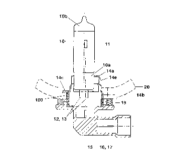
Figure 1 shows a side view of the preferred exemplary
embodiment of the invention in a dia-
grammatic, partially sectioned representation
with a reflector indicated by dashes
Figure 2 shows a top view of the connection between
the carrier sleeve of the lamp in accordance

CA 02290838 1999-11-25
- 4 -
with Figure 1 and the reflector of the
headlight
Figure 3 shows a cross section through the plastic cap
part and the carrier sleeve of the lamps from
Figure 1
Figure 4 shows a side view of the pressing-on spring
of the lamp illustrated in Figure 1, and
Figure 5 shows a top view of the pressing-on spring
illustrated in Figure 4.
The preferred exemplary embodiment of the invention is
a single-filament halogen incandescent lamp which is
provided for use in a motor vehicle headlight. This
lamp has a vitreous, essentially cylindrical lamp bulb
10 having a pinch foot l0a sealed in a gas tight
fashion. The dome lOb of the lamp bulb 10 is provided
with a light-absorbing coating. Serving as light source
is an incandescent filament 11 which is aligned
parallel to the lamp bulb axis and is connected in an
electrically conductive fashion to two supply leads 12,
13 which are guided out of the pinch foot l0a and
consist of molybdenum wire. The pinch foot l0a of the
lamp bulb 10 is fixed in a metal holder which consists
of the cup-like holder part 14a, the intermediate ring
14e and the annular carrier sleeve 14b. In addition to
the metal holder 14a, 14b, the lamp cap also has a
plastic cap part 15 which is provided with the electric
connections 16, 17 of the lamp and in which the annular
metal carrier sleeve 14b is anchored. The carrier
sleeve 14b has three reference noses 14c, situated in a
plane, and a pressing-on spring 100 for mounting the
lamp in the reflector 20 of a motor vehicle headlight.
The sealing of the reflector 20 is performed by means
of a silicone sealing ring 19 which bears against the
outer wall 20b of the reflector 20 and against the
plastic cap part 15. The design of the lamp in

CA 02290838 1999-11-25
- 5 -
accordance with the preferred exemplary embodiment, and
its use in a headlight are represented diagrammatically
in Figure 1.
Figure 2 shows details of the arrangement of the lamp
in the reflector 20 of the motor vehicle headlight. The
three reference noses 14c engage in the mounting
opening 21, constructed as lamp holder, of the
reflector 20, and bear against the inside 20a of the
reflector 20. They 14c are distributed equidistantly
over the circumference of the annular carrier sleeve
14b. The pressing-on spring 100 of the carrier sleeve
14b is arranged below a first reference nose 14c, and
bears resiliently against the edge 22 of the lamp
mounting opening 21. The purpose of fastening the
pressing-on spring 100 on the carrier sleeve 14b is
served by two lugs 14d which are integrally formed on
the annular carrier sleeve 14b, are angled inwards and
between which the pressing-on spring 100 constructed as
leaf spring is arranged with a clamping fit (Figure 3).
The lugs 14b form an acute angle with the carrier
sleeve wall. The leaf spring 100 consists of a spring
steel. Its shape is shown in Figures 4 and 5.
The leaf spring 100 has a V-shaped section 101 which is
arranged between two U-shaped sections 102, 103. The
U-shaped sections 102, 103 in each case connect a limb
of the V-shaped section 101 to a leaf spring end 104,
105. Each leaf spring end 104, 105 is equipped with two
teeth 104a, 105a, between which the corresponding lug
14d, angled from the carrier sleeve 14b, is arranged in
each case (Figure 3). The teeth 104a, 105a enclose an
angle of 105 degrees with the leaf spring ends 104,
105. The V-shaped section 101 reaches through a cut-out
in the carrier sleeve 14b, and after the lamp mounting
the rounded-off connecting region lOla arranged between
the two limbs of the V-shaped section 101 bears
resiliently against the edge 22 of the reflector
opening 21 constructed as lamp holder. The leaf spring

CA 02290838 1999-11-25
- 6 -
100 bears against the inner wall of the carrier sleeve
14b in the transition regions between the V-shaped
section 101 and the U-shaped sections 102, 103, as well
as in the transition regions between the U-shaped
sections 102 and 103 and the respective leaf spring end
104, 105.
The outside of the carrier sleeve 14b has a depression
14f in each case below the other two reference noses
14c. The edge 22 of the lamp mounting opening 21 of the
reflector 20 in each case has a prismatic bearing
surface 22a in the region of the two abovenamed other
reference noses 14c. The outside of the carrier sleeve
14b of the lamp cap bears with a clamping fit against
these two prismatic bearing surfaces 22a. The clamping
effect is produced by means of the pressing-on spring
100. The depressions 14f ensure that the outer edge
22a2, possibly affected by a burr, of the edge 22 of
the mounting opening 21 is arranged not to contact the
lamp cap and, in particular, not to contact the carrier
sleeve 14b.

Dessin représentatif
Une figure unique qui représente un dessin illustrant l'invention.
États administratifs

2024-08-01 : Dans le cadre de la transition vers les Brevets de nouvelle génération (BNG), la base de données sur les brevets canadiens (BDBC) contient désormais un Historique d'événement plus détaillé, qui reproduit le Journal des événements de notre nouvelle solution interne.

Veuillez noter que les événements débutant par « Inactive : » se réfèrent à des événements qui ne sont plus utilisés dans notre nouvelle solution interne.

Pour une meilleure compréhension de l'état de la demande ou brevet qui figure sur cette page, la rubrique Mise en garde , et les descriptions de Brevet , Historique d'événement , Taxes périodiques et Historique des paiements devraient être consultées.

Historique d'événement

Description Date
Demande non rétablie avant l'échéance 2008-11-25
Le délai pour l'annulation est expiré 2008-11-25
Réputée abandonnée - omission de répondre à un avis sur les taxes pour le maintien en état 2007-11-26
Inactive : CIB de MCD 2006-03-12
Lettre envoyée 2004-12-07
Toutes les exigences pour l'examen - jugée conforme 2004-11-23
Exigences pour une requête d'examen - jugée conforme 2004-11-23
Requête d'examen reçue 2004-11-23
Demande publiée (accessible au public) 2000-06-01
Inactive : Page couverture publiée 2000-05-31
Lettre envoyée 2000-03-21
Inactive : CIB attribuée 2000-02-21
Inactive : CIB en 1re position 2000-02-16
Inactive : Transfert individuel 2000-02-10
Inactive : Lettre de courtoisie - Preuve 1999-12-29
Inactive : Certificat de dépôt - Sans RE (Anglais) 1999-12-22
Demande reçue - nationale ordinaire 1999-12-21

Historique d'abandonnement

Date d'abandonnement Raison Date de rétablissement
2007-11-26

Taxes périodiques

Le dernier paiement a été reçu le 2006-10-18

Avis : Si le paiement en totalité n'a pas été reçu au plus tard à la date indiquée, une taxe supplémentaire peut être imposée, soit une des taxes suivantes :

  • taxe de rétablissement ;
  • taxe pour paiement en souffrance ; ou
  • taxe additionnelle pour le renversement d'une péremption réputée.

Les taxes sur les brevets sont ajustées au 1er janvier de chaque année. Les montants ci-dessus sont les montants actuels s'ils sont reçus au plus tard le 31 décembre de l'année en cours.
Veuillez vous référer à la page web des taxes sur les brevets de l'OPIC pour voir tous les montants actuels des taxes.

Historique des taxes

Type de taxes Anniversaire Échéance Date payée
Taxe pour le dépôt - générale 1999-11-25
Enregistrement d'un document 2000-02-10
TM (demande, 2e anniv.) - générale 02 2001-11-26 2001-11-05
TM (demande, 3e anniv.) - générale 03 2002-11-25 2002-11-01
TM (demande, 4e anniv.) - générale 04 2003-11-25 2003-11-06
TM (demande, 5e anniv.) - générale 05 2004-11-25 2004-11-04
Requête d'examen - générale 2004-11-23
TM (demande, 6e anniv.) - générale 06 2005-11-25 2005-11-02
TM (demande, 7e anniv.) - générale 07 2006-11-27 2006-10-18
Titulaires au dossier

Les titulaires actuels et antérieures au dossier sont affichés en ordre alphabétique.

Titulaires actuels au dossier
PATENT-TREUHAND-GESELLSCHAFT FUER ELEKTRISCHE GLUEHLAMPEN MBH
Titulaires antérieures au dossier
FRITZ ECKHARDT
PETER HELBIG
Les propriétaires antérieurs qui ne figurent pas dans la liste des « Propriétaires au dossier » apparaîtront dans d'autres documents au dossier.
Documents

Pour visionner les fichiers sélectionnés, entrer le code reCAPTCHA :


Pour visualiser une image, cliquer sur un lien dans la colonne description du document. Pour télécharger l'image (les images), cliquer l'une ou plusieurs cases à cocher dans la première colonne et ensuite cliquer sur le bouton "Télécharger sélection en format PDF (archive Zip)" ou le bouton "Télécharger sélection (en un fichier PDF fusionné)".

Liste des documents de brevet publiés et non publiés sur la BDBC .

Si vous avez des difficultés à accéder au contenu, veuillez communiquer avec le Centre de services à la clientèle au 1-866-997-1936, ou envoyer un courriel au Centre de service à la clientèle de l'OPIC.


Description du
Document 
Date
(aaaa-mm-jj) 
Nombre de pages   Taille de l'image (Ko) 
Dessin représentatif 2000-05-22 1 6
Description 1999-11-24 6 259
Abrégé 1999-11-24 1 20
Revendications 1999-11-24 2 68
Dessins 1999-11-24 4 63
Certificat de dépôt (anglais) 1999-12-21 1 164
Courtoisie - Certificat d'enregistrement (document(s) connexe(s)) 2000-03-20 1 113
Rappel de taxe de maintien due 2001-07-25 1 112
Rappel - requête d'examen 2004-07-26 1 117
Accusé de réception de la requête d'examen 2004-12-06 1 177
Courtoisie - Lettre d'abandon (taxe de maintien en état) 2008-01-20 1 175
Correspondance 1999-12-21 1 15