Note : Les descriptions sont présentées dans la langue officielle dans laquelle elles ont été soumises.
CA 02295713 2000-O1-06
WO 99/03747 PCT/AU98/00511
1
"Pusli-on Closure"
Technical Field
The present invention relates to a closure for containers. such as
bottles, which can be pushed onto the container but then screwed off.
Background Art
It is known to provide closures that may be applied to the neck of a
container in a push-on manner but which are screwed off the container,
namely so-called push-on closures. Such container and closure
combinations usually rely upon the use of very fine complementary threads
so on each of the closure and the container. The closure is placed over the
neck
of the container and pushed relatively downwardly onto the neck. The two
complementary screw threads ride over one another as the closure is forced
onto the neck of the container. When the closure is to be removed the
closure is rotated relative to the container such that the complementary
threads engage and so allow the closure to be removed from the neck of the
container.
Such closures can be advantageous as they do not require a complex
capping chuck that for normal screw-on closures must. while attaching the
closure. also rotate the closure relative to the neck sufficiently to ensure
2o sufficient torque is applied to the closure to seal the container. A
difficulty
associated with push-on closures is, however, that the fine threads on the
container and the closure are inclined to strip and override one another if
there is any longitudinal resistance to removal of the closure. Such
resistance is likely to be encountered, for example, if the closure includes a
tamper evident band. The present invention is directed to an alternative
construction of a push-on closure that allows the use of fine threads to be
avoided if desired.
Disclosure of Invention
In a first aspect the present invention relates to a closure and a
container in combination, the container having a neck that is provided on an
outer surface with a mufti-start thread comprising alternating ridges and
grooves, each groove of the thread commencing at or adjacent an upper free
end of the neck and terminating at a recess formed in the neck. the closure
including a substantially circular top portion and a depending skirt, the
skirt
being provided on a radially inner surface with a plurality of lugs, the lugs
being spaced apart circumferentially by distances corresponding to the
CA 02295713 2000-O1-06
WO 99/03747 PCT/AU98/00511
2
spacing of the grooves of the thread and being spaced axially from an inside
surface of the top portion by a distance such that on being pushed relatively
downwardly onto the neck of the container each of the lugs will engage with
one of the recesses formed in the neck as the closure sealingly engages with
the neck of the container, a ramp member being located adjacent each recess
such that upon relative rotation of a closure that has been pushed onto the
neck of a container at least some of the lugs will bear against at least some
of
the ramp members and be directed by the ramp members into a
corresponding one of the grooves in the thread to allow the closure to be
unscrewed from the neck of the container.
In further aspects, the present invention relates to closures and to
containers for inclusion in the combination according to the first aspect of
the invention.
In a preferred embodiment of the invention the multi-start thread
includes from four (4) to eight (8) ridges and grooves, more preferably six
(6)
ridges and grooves. Each groove preferably starts just below a tapered lip on
the free end of the neck of the container. The tapered lip serves to
facilitate
the radially outward deflection of the lugs as the closure is pushed onto the
neck and over the thread ridges thereon. Each groove of the thread
2o preferably finishes in recesses comprised by a substantially annular recess
formed in the neck which has the ramps extending across it at appropriate
intervals.
The closure preferably has on the inside surface of the skirt a number
of lugs equal to the number of grooves in the thread. It would. however, be
possible to have fewer lugs than thread grooves, in which case some thread
grooves would go unused. Alternatively, it is possible to have more Iugs than
there are grooves, in which case the additional lugs would be deflected over
ridges in the thread as the closure is unscrewed. In any of these cases.
however, the lugs that are to be guided up the thread grooves as the closure
is
unscrewed must be radially spaced apart by distances equal to the
circumferential spacing of the thread grooves. The lugs also preferably lie in
a single horizontal plane on the inner surface of the skirt.
The thread is preferably formed of a plurality of grooves each of which
has a square cross-sectional shape. Each of the interposed ridges preferably
has an upper edge that is curved in cross-section. This curvature facilitates
CA 02295713 2000-O1-06
WO 99/03747 PCT/AU98/00511
3
the lugs being pushed over the ridges as the closure is applied to the
container.
Each iug preferably has a longitudinal axis orientated in a
circumferential direction. One end of each lug is preferably chamfered and
can end in a point. The chamfer results in the lugs being able to more easily
cooperate with the corresponding ramp member as the relative unscrewing
rotation of the closure from the neck of the container commences.
There is preferably a ramp member adjacent the end of each thread
groove and so inclined that a lug that is brought into contact with the upper
1o side of the ramp member will be caromed upwardly into the bottom end of
the associated thread groove. In a preferred embodiment, the upper side of
each ramp lies in the same helical locus as the upper side of the thread ridge
(which is also the lower side of the adjacent upper groove) to which the ramp
is connected. Such an arrangement ensures that the lug on being brought
into contact with the upper side of the ramp llleIllber 1S sIllOOthly caromed
upwardly into the associated thread groove.
It is highly desirable that some form of supplementary sealing means
be positioned between the neck of the container and the closure. In a
particularly preferred embodiment of the present invention, the sealing
2o means comprises a deformable sealing rib integral with the closure as is
described in US patent specification 5,423,444, or variants thereof that are
described in Australian patent specification 637,706, and Australian patent
specification 74.544/94. The contents of the foregoing patent specifications
are incorporated herein by reference.
For example, the sealing means can comprise an annular sealing rib
projecting downwardly from an underside of the top portion, the rib
including a first portion which is contiguous with the top portion and having
an inner surface, which inner surface lies radially inwardly of the skirt
portion, and a second, frusto-conical, portion contiguous with the first
portion and separated from the top portion by the inner surface of the first
portion. the second portion extending radially inwardly to terminate in a
circular free edge, the first portion having an internal diameter relative to
the
external diameter of the neck of the container such that during attachment of
the closure with the neck. the second portion will be engaged by a free end of
the neck of the container and folded back towards, and preferably against,
CA 02295713 2000-O1-06
WO 99/03747 PCT/AU98/00511
4
the inner surface of the first portion of the rib to form a seal between the
neck of the container and the closure.
In one embodiment, the first portion of the sealing rib can be formed
radially inwardly of the skirt portion with an annular space therebetween.
The first portion in another embodiment can be in continuous abutment with
the skirt portion. The first portion of the rib can comprise a thickening of
the
skirt portion adjacent the top portion. In a further embodiment, the sealing
rib can include a substantially annular region of weakness that is formed
around an inside surface of the sealing rib approximately at the join between
1o the first and second portions of the sealing rib. The first portion of the
rib
can also increase in thickness as it extends away from the top portion of the
closure. At or adjacent the free circular edge. the upper surface of the
second
portion of the sealing rib can have a continuous or segmented annular ridge.
The underside of the top portion of the closure can also be provided with a
15 segmented or continuous annular ridge positioned inwardly and adjacent the
first portion of the sealing rib. The sealing rib can also include a third
portion connected to the second portion at or adjacent the circular edge and
extending generally in a direction away from the top portion, the third
portion being substantially no thicker than the second portion and having a
20 length longer than its thickness.
Alternatively, the seal could be any one of a variety of known sealing
arrangements. A sealing wad of a compressible material such as a synthetic
plastics foam could be used as could a flowed-in gasket. In another
embodiment, the seal could be a cylindrical boss or tube projecting axially
25 from the underside of the top portion of the closure and adapted to
sealingly
engage with the radially inner surface of the neck of the container. In a
still
further arrangement, the sealing means could comprise a closure having a rib
formed on the inside surface of the top portion inside which is a sealing
membrane formed by rotary moulding or another suitable technique.
3o It is also highly preferred to form the closure with a tamper evident
band that will show a consumer whether any attempt. either successful or
unsuccessful. has been made to remove the closure frOIIl the container. In a
particularly preferred embodiment of the present invention, the tamper
evident band is made according to the disclosure of Australian patent
35 specification 668,197 or US patent specification 5676269. The contents of
the foregoing patent specifications are incorporated herein by reference.
CA 02295713 2000-O1-06
WO 99/03747 PCT/AU98/00511
In one embodiment, the band can comprise a generally cylindrical
body portion and a segmented rib extending inwardly of the body portion and
adapted to provide a lip having an inner free edge to engage under a retaining
flange extending outwardly from the neck of the container. The combined
5 length of the segmented ribs is preferably equal to at least 50% of the
internal
circumference of the band. The inner surface of the band can have a
plurality of radially inward projections extending from above the free edge of
the band and not extending beyond the inner free edge of the lip. The band
in one embodiment can also have on its outer surface a plurality of
longitudinally extending areas of localised thickening separated from each
other by areas that are not so thickened. The areas of thickening increase the
longitudinal stiffness of the body portion but still allow the body portion to
move radially outwardly as it is moved over the retaining flange on the
container on attachment of the closure to the container.
In a still further embodiment, the rib segments on the inner surface of
the band can have an upper surface facing generally towards the top portion
of the closure and an underside facing generally away from the top portion,
with the upper surface of each rib segment comprising a first surface
contiguous with the body portion of the band, which surface slopes inwardly
and downwardly away from the top portion, and a second surface which
extends radially inwardly from the inner terminus of the first surface and has
a slope angle substantially normal to the skirt portion of the closure.
Other known tamper evident bands could alternatively be used.
Whichever type of tamper evident band is used it is important to ensure that
the frangible bridges connecting the band to the lower end of the skirt of the
closure do not require a force to rupture them which exceeds the force that
can be applied to them by the action of the lugs being moved up the thread
grooves. If this were to happen then the lugs will shear or, alternatively,
the
lugs will ride over the thread ridges as the closure is rotated.
Brief Description of Drawin~,s
The following description of a preferred embodiment of the present
invention is provided as an example of the invention and is described with
reference to the accompanying drawings, in which:-
Fig. 1 is a sectional view of a closure according to one embodiment of
the present invention, with the closure depicted applied to the neck of a
container also according to one embodiment of the present invention;
CA 02295713 2000-O1-06
WO 99/03747 PCT/AU98/00511
6
Fig. 2 is a detailed side elevational view of the thread on the container
depicted in Fig. 1;
Fig. 3 is a cross sectional view along line III-III of the closure as
depicted in Fig. 4;
Fig. 4 is a vertical sectional view along line IV-IV of the closure as
depicted in Fig. 3; and
Fig. 5 is a cross sectional view along line V-V of the closure as depicted
in Fig. 4.
Best Mode for Carrying Out the Invention
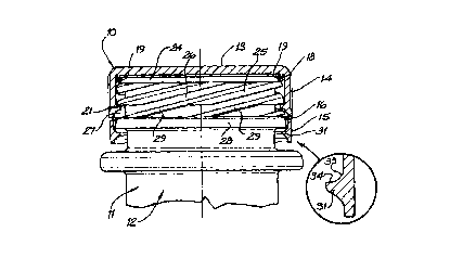
The closure 10 according to the present invention is depicted in Fig. 1
on the neck 11 of a container 12 according to the present invention.
The closure 10 comprises a circular top 13 and a cylindrical skirt 14. A
tamper evident band 15 is connected by a plurality of frangible bridges 16 to
the lower edge of the skirt 14. The inside surface of the closure 10 is
25 provided with a sealing rib 17. This sealing rib is formed integrally with
the
top 13 of the closure 10 and has a substantially cylindrical portion 18 spaced
slightly inwardly from the skirt 14. While depicted positioned slightly
inwardly of the skirt 14. it can be readily envisaged that the cylindrical
portion 18 could be in abutment or integral with the skirt 14 of the closure
10. The lower end of the cylindrical portion 18 is connected to a frusto-
conical portion 19. As depicted in Fig. 4, a sharp edge 20 is provided
between the first cylindrical portion 18 and the second frusto-conical portion
19. On the application of the closure 10 to a container 12. a free end 23 of
the neck 11 will engage with the frusto-conical portion 19 and fold it back
towards, and preferably into contact with, the radially inner surface of the
cylindrical portion 18. The sharp edge 20, while not essential. does define a
line of weakness between the two portions 18.19 and serves to facilitate even
folding back of the frusto-conical portion 19 relative to the cylindrical
portion 18 when the closure is attached to a container. Once attached to the
container 12. the folded back frusto-conical portion 19 forms a fluid-tight
seal
with the radially outer surface of the neck 11.
Again, while not depicted, it can be readily envisaged that the upper
surface of the frusto-conical portion 19 can have adjacent its free edge, an
annular ridge that is adapted to engage with the underside of the top 13 when
the frusto-conical portion 19 is folded back towards the cylindrical portion
18. A complementary annular ridge that is positioned on the underside of
r
CA 02295713 2000-O1-06
WO 99/03747 PCT/AU98/0051 I
7
the top 13 and radially inward of the cylindrical portion 18 can also be
readily envisaged.
Six lugs 21 are equiangularly disposed around the radially inner
surface of the skirt 14. The lugs 21 are disposed to lie in a single
horizontal
plane through the skirt 14 above the frangible bridges 16 and below the
sealing rib 17. Each lug 21 has a longitudinal axis lying in the plane. At the
end of each lug 21 that will be the leading end when the closure 10 is
unscrewed from the neck 11 (ie. the left hand end of the lugs 21 depicted on
the closure in Fig. 4), the lug is tapered to a point 22.
The neck 11 of the container 12 has on its outer surface and
immediately adjacent its free end 23 an outwardly tapered section 24. Below
the section 24 on the outer surface of the neck 11 are six alternating helical
ridges 25 and grooves 26. The ridges 25 and the grooves 26 comprise a multi-
start screw thread. Below the thread on the outer surface of the neck 11 is an
annular recess 27. The annular recess 27 lies in a horizontal plane
surrounding the neck 11 and has a depth equal to that of the grooves 26. It is
thus overhung on its upper side by the lower ends of the ridges 25. On its
lower side the annular recess 27 is bounded by an external retaining flange
28 for the tamper evident ring 15 of the closure 10. There are also six (6)
ramps 29 located in the annular recess 27. Each ramp 29 is connected at its
lower end to the retaining flange 28 and at its upper end to the lower end of
one of the thread ridges 25. The upper surface of the ramp 29 lies in the
same helical locus as the upper surface of the thread ridge 25 (which is also
the lower surface of the adjacent upper groove 26) to which the ramp 29 is
connected.
In use, a closure 10 will normally be positioned over the neck 11 of the
container 12 in a capping chuck. The closure 10 is then pushed vertically
downwardly by the chuck. The lugs 21 can then slide over the outwardly
tapered section 24 of the neck 11 and then over the thread ridges 25 until the
lugs are at a level just slightly below the upper edge of the annular recess
27.
The closure 10 is then turned slightly in a clockwise direction (as seen in
Fig.
1) about its longitudinal axis relative to the container 12 by the chuck. This
turning movement serves to locate the lugs 21 in the recess 27 free from the
ramps 29 and lodged under the lower ends of corresponding ones of the
thread ridges 25.
CA 02295713 2000-O1-06
WO 99/03747 PCT/AU98/00511
8
As the closure 10 is being pushed onto the neck 11, the sealing rib 17
will be contacted by the free end 23 of the neck 11. The frusto-conical
portion 19 will be folded back towards and preferably against the inside
surface of the cylindrical portion 18 of the sealing rib 17 by the neck 11.
The
sealing rib 17 will thus form its seal between the closure and the container
12
specifically against the outwardly tapered section 24 and the free end 23 of
the neck 11.
A further effect of the application of the closure 10 to the neck 11 is
that inwardly directed rib 30 on the inner surface of the tamper evident band
15, which provides an inwardly directed lip, is pushed past the retaining
flange 28 and engages under the retaining flange 28 once the closure 10 is
fully closed onto the neck 11. The closure 10 can then only be removed from
the container 12 by the rupture of the frangible bridges 16 leaving the tamper
evident ring 15 on the neck of the container 12.
The rib 30 is made up of a series of rib segments 31 separated by short
breaks 32 and in the depicted embodiment constitute about 85% of the
circumference of the band 15. The short breaks 32 provide circumferential
flexibility to the band 15 and allow the rib 30 to pass over the retaining
flange 28 without creating a stress sufficient to break the frangible bridges
16.
2o Each rib segment 31 has an upper side directed towards the top 13 and
an underside directed away from it. The upper side includes a radially outer
frusto-conical surface 33 and a radially inner annular surface 34. The
annular surface 34 lies in a plane normal to the longitudinal axis of the
closure 10 while the frusto-conical surface 33 is inclined inwardly and
downwardly away from the top 13. The presence of the frusto-conical
surface 33 assists in the moulding of the closure 10 as it prevents or at
least
substantially reduces the production of closures having deformed ribs 30.
When the container is to be opened a user turns the closure in an anti-
clockwise fashion (as seen in Fig. 1). The lugs 21 are then brought into
contact with respective ones of the ramps 29 and so guided into the lower
ends of the grooves 26 of the thread. The resulting relative upward
movement of the lugs 21, and thus the closure 10, to the neck 11 brings the
rib segments 31 into contact with the underside of the retaining flange 28.
Further rotational IIlOVBIIlellt of the closure 10 raises the closure 10 still
further on the neck 11 and eventually causes the rupture of the frangible
CA 02295713 2000-O1-06
WO 99/03747 PCT/AU98/00511
9
bridges 16. The rotation may then be continued until the closure 10 can be
lifted free from the neck 11.
It will be appreciated by persons skilled in the ar t that numerous
variations and/or modifications may be made to the invention as shown in
the specific embodiments without departing from the spirit or scope of the
invention as broadly described. The present embodiments are, therefore, to
be considered in all respects as illustrative and not restrictive.