Note : Les descriptions sont présentées dans la langue officielle dans laquelle elles ont été soumises.
CA 02298920 2006-03-27
119361-1001 PATENT
TANK CLEANING APPARATUS
TECHNICAL FIELD
S This invention relates generally to the cleaning of
sludge from storage tanks, and more particularly to an
apparatus for circulating crude oil through a crude oil
storage tank to facilitate resuspension and removal of the
sludge into the crude oil.
BACKGROUND AND SUMMARY OF THE INVENTION
The manufacture of petroleum-based products begins
with the pumping of crude oil from one or more wells. The
crude oil is directed from the wells into one or more
storage tanks comprising a tank battery. The oil is then
transported most commonly by pipeline to storage tanks at
oil refineries prior to processing.
As will be apparent, when contained in a storage tank
crude oil is in a quiescent state. This allows any solid
components and the heavier liquid components comprising the
crude oil to settle to the bottom of the storage tank in
CA 02298920 2000-03-03
-2-
the form of sludge. Sludge build up in the bottom of a
crude oil storage tank is undesirable for a number of
reasons, the most apparent of which is reduction of the
storage capacity of the tank. A number of systems have
heretofore been developed to reduce sludge build up in
crude oil storage tanks. Several of these techniques
involve the circulation of crude oil into the bottom of the
tank in an attempt to resuspend the sludge in the crude
oil.
One problem that has characterized prior tank cleaning
apparatus and sludge removal systems is a significant
pressure drop and flow turbulence created by the
perforations and/or around the ninety degree bends that
exist in present jetting apparatus. Reduction in pressure
and flow turbulence cause a reduction in the flow rate, or
velocity, of the crude oil that is being used to resuspend
the sludge, ultimately leading to a significant reduction
in system efficiency.
The present invention comprises a tank cleaning
apparatus which overcomes the foregoing and other problems
that have long since characterized the prior art. In
accordance with the broader aspects of the invention, crude
oil is pumped through a long, straight passageway and is
discharged therefrom through a nozzle into the bottom of a
crude oil storage tank. By this means the significant
pressure drop which has characterized the operation of
CA 02298920 2000-03-03
-3-
prior sludge removal systems is eliminated. For example,
the present invention has less than 50% of the pressure
drop of the prior systems known to the inventor.
Also, the elimination of the sharp bends through the
apparatus greatly reduces turbulence in the flow. This in
turn allows for a more focused and straighter discharge
from the nozzle, i.e., a laminar flow stream, which
substantially increase the efficiency of the system.
Another important aspect of the invention is the
location of all moving components externally of the tank,
excepting the outlet end of the straight pipe and the
interior side of the gimbal. The apparatus may be
permanently left on the tank without concern for the
apparatus becoming inoperable due to sludge buildup within
the apparatus, thus providing a significant advantage over
the prior sludge removal systems.
The present invention may employ reciprocating
movement of the gimbal and straight pipe in one plane in
order to substantially increase system efficiency.
It is an advantage of the present invention to provide
a tank cleaning apparatus which does not require the tank
to be removed from service for cleaning.
It is an advantage of the present invention to
eliminate the need for manual cleaning or opening the tank
to the outside environment during cleaning.
CA 02298920 2000-03-03
-4-
It is an advantage of the present invention to
eliminate the cost and need for manual cleaning prior to
tank inspection and servicing.
It is an advantage of the present invention to allow
tank operators to decontaminate their tanks for service
changes without decommissioning the tank.
It is an advantage of the present invention to operate
on the tank as a closed system, eliminating the need to
vent the tank to atmosphere prior to, during, or after
cleaning.
It is an advantage of the present invention to allow
either use of the oil from the tank itself or the use of a
fluid from an outside supply source, such as a source of
cutter stock, to clean the tank.
It is an advantage of the present invention to provide
a tank cleaning apparatus which will interface between two
dissimilar environments, i.e., the exterior, natural
atmosphere outside of the tank and the interior contents of
the tank, thereby eliminating the need to decommission the
tank before, during, or after cleaning by permanently
installing the tank cleaning apparatus on the tank.
CA 02298920 2000-03-03
-5-
BRIEF DESCRIPTION OF THE DRAWIINGS
A more complete understanding of the invention may be
had by reference to the following Detailed Description when
taken in conjunction with the accompanying Drawings,
wherein:
Figure 1 is a front view of a sludge removal system
incorporating the invention;
Figure 2 is a vertical sectional view of the sludge
removal system of Figure 1;
Figure 3 is an enlargement of a portion of Figure 2;
Figure 4 is a horizontal sectional view of the sludge
removal system of Figure 1;
Figure 5 is an enlargement of a portion of Figure 4;
and
Figure 6 is a diagrammatic illustration of a hydraulic
circuit useful in the practice of the invention.
Figure 7 is a schematic representation of another
embodiment of a tank cleaning apparatus of the present
invention installed on a crude oil tank for operation.
Figure 8 is a top view in partial section of the tank
cleaning apparatus of Figure 7.
Figure 9 is a view along line 9-9 of Figure 8.
Figure 10 is view along line 10-10 of Figure 9.
Figure 11 is a side sectional view of an embodiment of
the tank cleaning apparatus of Figure 7 in its dormant
state.
CA 02298920 2000-03-03
-6-
DETAILED DESCRIPTION
Referring now to the drawings and particularly to
Figure 1 thereof, there is shown a sludge removal system 10
comprising an embodiment of the invention. A system
mounting bracket 12 supports the operating components of
the sludge removal system 10, which may include an
elevation hydraulic cylinder 14 and an azimuth hydraulic
cylinder 16. The elevation hydraulic cylinder 14 has a
piston rod 18 which is connected to an elevation bracket 20
by a clevis 22. Likewise, the azimuth hydraulic cylinder
16 has a piston rod 24 which is connected to an azimuth
gimbal assembly 26 by a clevis 28.
Referring to Figure 2, the sludge removal system 10 is
utilized in a crude oil storage tank 30, it being
understood that the system 10 is also adapted to other
applications. The tank 30 has a bottom wall 32 and a
plurality of side walls 34, only one of which is shown in
detail. The side wall 34 is provided with an access port
36 having the sludge removal system 10 mounted therein.
Although a particular storage tank configuration is
illustrated in the Drawings, the sludge removal system 10
is adapted for use in conjunction with other types and
kinds of crude oil storage tanks.
The sludge removal system 10 includes a crude oil
delivery pipe 40 which extends through the azimuth gimbal
assembly 26 and terminates in a nozzle 42. A pipe 40 is
CA 02298920 2000-03-03
connected to a flexible hose 44 through a ball valve 46.
In the use of the system 10, a pump (not shown in Figure 2)
withdraws crude oil from the tank 30 and directs the crude
oil under high pressure through the flexible hose 44, the
ball valve 46, the pipe 40, and the discharge nozzle 42.
The crude oil is discharged from the nozzle 42 at high
velocity into engagement with sludge formed at the bottom
32 of the tank 30, whereupon the sludge is resuspended in
the crude oil contained within the tank.
It is important that the passageway comprising the
flexible hose 44, the ball valve 46, the pipe 40, and the
nozzle 42 define a length of at least 20 diameters that
does not include obstructions such as sharp bends,
perforated members, etc. in order to minimize pressure drop
and thereby maximize both the flow rate and the velocity of
the crude oil exiting the discharge nozzle 42. Preferably,
the discharge nozzle 42 has a smooth bore to enhance the
creation of a discharge jet of fluid from the nozzle 42.
The system mounting bracket 12 is secured to the
access port 36 by a plurality of fasteners 50 which also
support a mounting flange 52. As is best shown in Figure
3, the mounting flange 52 includes a first portion 54 which
secured directly to the access port 36 and a second portion
56 which is secured to the first portion 54 by fasteners
58.
CA 02298920 2000-03-03
_g_
The clevis 22 connects the piston rod 18 of the
elevation hydraulic cylinder 14 to the elevation bracket 20
which is secured to an elevation gimbal 62 by fastener 64.
Referring again to Figure 3, the elevation gimbal 62
supports the azimuth gimbal 26 on the mounting flange 54
for pivotal movement about a horizontal axis 66 defined by
elevation pivot pins 68 (not shown in Figures 2 and 3).
The opposite ends of the mating surfaces are provided with
seals 70, and lubrication is provided to the mating
surfaces through a fitting 72.
The pivot pins 68 are secured in the mounting flange
54 and rotatably support the elevation gimbal 62. Needle
bearings 72 are mounted between the pivot pins 68 and the
elevation gimbal 72 and serve to support the elevation
gimbal 62 for pivotal movement about the axis 66 under
conditions of minimal resistance. In this manner the
elevational positioning of the nozzle 42 of the sludge
removal system 10 is readily controlled under the action of
the elevation hydraulic cylinder 14.
The azimuth hydraulic cylinder 16 is connected to the
system mounting bracket 12 by a bracket 78. The clevis 28
secures the piston rod 24 of the azimuth hydraulic cylinder
16 to a bracket 80 which is in turn connected to a coupling
82 comprising part of the pipe 40. Thus, upon actuation of
the azimuth hydraulic cylinder 16, the azimuth gimbal
CA 02298920 2000-03-03
-9-
assembly 26 is caused to pivot relative to the tank 30
about an axis 84.
Referring again to Figure 5, the azimuth gimbal
assembly 26 is supported for pivotal motion relative to the
elevation gimbal 62. The space between the azimuth gimbal
assembly 26 and the elevation gimbal 62 is isolated by
seals 86. Suitable lubrication is provided in the space
between the azimuth gimbal assembly 26 and the elevation
gimbal 62 by a suitable fitting (not shown).
Referring again to Figure 3, the axis 84 is defined by
the azimuth pivot pins 90 which are mounted in the
elevation gimbal 62. Needle bearings 92 are mounted
between the azimuth pivot pins 90 and the azimuth gimbal
assembly 26 to assure pivotal movement of the azimuth
gimbal assembly 26 under the action of the hydraulic
cylinder 16 without undue restriction. Contamination of
the bearings 92 is prevented by suitable seals 94.
Referring now to Figure 6, there is shown a hydraulic
circuit 100 useful in the practice of the invention of
Figures 1-5. A pump assembly 102 supplies pressurized
hydraulic fluid to the elevation hydraulic cylinder 14 and
the azimuth hydraulic cylinder 16 through a plurality of
valves and conduits. In the operation of the hydraulic
circuit 100, the azimuth hydraulic cylinder 16 is operated
to sweep the nozzle 42 back and forth horizontally between
the limits of its travel. The elevation hydraulic cylinder
CA 02298920 2000-03-03
-10-
14 is initially actuated to position the nozzle 42 at its
lower most orientation relative to the tank 30. At the end
of each oscillation of the azimuth hydraulic cylinder 16 an
index cylinder 104 actuates the elevation hydraulic
cylinder 14 to pivot the nozzle 42 upwardly one increment.
In a prototype system 10, the nozzle 42 starts
operation at an angle of -10° to horizontal and indexes up
one (1°) degree at the end of each horizontal sweep of
nozzle 42. Preferably, the end points of each sweep of the
nozzle define an angle of about 120°, and each sweep is
about thirty minutes in duration. When the nozzle reaches
the horizontal plane (0°), pivotal movement about the
vertical axis is terminated and the nozzle is pivoted
downwardly and returned to the starting point.
The indexing up of the nozzle allows for an ever-
increasing sweep radius with respect to the bottom of the
tank as the nozzle and sludge are swept outwardly toward
the opposite side of the tank from the access port 36 and
nozzle 42. By this means the sludge removal system 10 of
the present invention is effective to remove sludge from a
crude oil storage tank much more efficiently than has
heretofore been possible.
As may be seen in Figure 2, the ball valve 46 and 40
extending externally of the tank 30 provide an external,
visual indication of the direction the nozzle 42 is
discharging fluid within the tank. It is contemplated that
CA 02298920 2000-03-03
-11-
the control system effected by the hydraulic circuit 100
may be placed on manual control so that the direction of
the nozzle 42 and fluid jet discharge therefrom may be
manually selected.
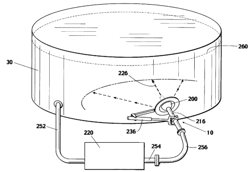
Referring now to the example of Figures 7-11, a more
preferred embodiment of the sludge removal system 10, also
referred to as a crude oil tank cleaning apparatus 10,
will be described. Referring to Figure 7, the crude oil
tank cleaning apparatus 10 is used for directing a high
velocity stream or jet 226 of fluid into the tank 30 in
order to resuspend or remove sludge from the tank 30.
Referring to Figure 8, the apparatus 10 may be generally
described as comprising a gimbal 200 having a substantially
straight passageway 202 extending through the gimbals a
mounting bracket 204 for sealingly and rotatably mounting
the gimbal 200 in a wall 206 of the tank 190 so that the
gimbal 200 has an interior side 208 exposed to the interior
210 of the tank 190 and an exterior side 212 exposed to the
exterior 214 of the tank 190; and a straight length of pipe
216 sealingly mounted in the gimbal passageway 202.
The pipe 216 has an inlet end 218 on the exterior side
212 of the gimbal 200 for connecting the pipe 216 to a high
pressure fluid source 220 (best seen in Figure 7)and an
outlet end 222 on the interior side 208 of the gimbal 200.
The inlet and outlet ends 218, 222 of the pipe define a
linear flow passageway 224 through the pipe 216 for
CA 02298920 2000-03-03
-12-
discharging the fluid in a fluid jet 226 into the tank 190
so that the fluid jet 226 (Fig. 7) is about collinear with
the flow passageway 224.
In the preferred embodiment, the pipe discharges the
fluid in a high velocity, laminar flow stream. The pipe
216 is designed and sized to laminarize the fluid
discharged from the pipe 216. This may be accomplished by
using flow straightening vanes inside the flow passageway
224 of the pipe 216. In the preferred embodiment, the flow
laminarization is achieved by sizing the straight pipe 216
so that the length of the pipe 216 from the interior
terminus 232 of the outlet end 222 to the exterior terminus
234 of the inlet end 218 is at least twenty pipe diameters.
As exemplified in Figure 8, the outlet end 222 of the pipe
216 extends beyond the gimbal 200 and defines the interior
terminus 232 of the pipe on the interior side 208 of the
gimbal 200, the inlet end 218 of the pipe 216 extends
beyond the gimbal 200 and defines the exterior terminus 234
of the pipe on the exterior side 212 of the gimbal 200, and
the pipe 216 is straight between the interior terminus 232
and the exterior terminus 234.
Referring to the example of Figure 8, the gimbal 200
is spherically shaped. More preferably, the gimbal 200 is
a sphere of solid material, such as mild steel.
Referring to the example of Figure 8, the preferred
apparatus 10 includes an actuator 236 for reciprocating the
CA 02298920 2000-03-03
-13-
gimbal 200 and pipe 216 between selected positions. The
actuator has a first end 238 connected to a rotatable
portion of the gimbal 200 and a second end 240 connected to
a stationary portion of at least one of the tank 190 or the
mounting bracket 204. Preferably, the first end 238 of the
actuator 236 is connected to the exterior side 212 of the
gimbal 200 and the second end 240 of the actuator 236 is
connected on the exterior side 214 of the tank 190 so that
the interior side 208 of the gimbal 200 and the outlet end
222 of the pipe 216 are the only moving components of the
apparatus 10 exposed to the interior of the tank 190. The
actuator 236 may be used to reciprocate the gimbal 200 and
pipe 216 about a selected axis. In the prototype apparatus
10, the actuator 236 reciprocates the gimbal 200 and pipe
216 about a vertical axis 242 (Figure 9).
Preferably, the actuator 236 reciprocates the gimbal
200 in pipe 216 through an arc of at least 120°. The
preferred actuator 236 allows adjustment of the length of
stroke of the actuator, thereby allowing the operator to
preselect the arc through which the gimbal 200 and pipe 216
reciprocate. The mounting bracket 204 may be used to
adjust the position of the gimbal 200 in the manway 266,
i.e., to position the gimbal 200 toward and away from the
interior of the tank, if the wall 206 of the tank is
limiting the sweep angle of the apparatus 10. Preferably,
the actuator 236 also includes a variable timer so that the
CA 02298920 2000-03-03
-14-
operator may select the oscillation time of the apparatus
10.
On smal l tanks , the actuator 2 3 6 may be e1 iminated .
The gimbal 200 may be fixedly positioned to angle the
discharge of the pipe 216 and fluid jet 226 into the tank
and create a cyclonic flow of fluid in the tank. On large
tanks 190, multiple tank cleaning apparatus 10 may be
installed at intervals around the tank in order to shorten
the cleaning time or to enhance the efficiency of the
cleaning apparatus 10.
As previously mentioned, the duration or cycle time of
the preferred apparatus 10 is a selectable function which
may be varied depending on the application. Factors which
influence the optimal cycle time of the apparatus 10
include the viscosity of the oil in the tank, the density
of the sludge, the accumulation depth of the sludge, and
whether the sludge has accumulated to a depth above the
elevation of the apparatus 10.
Referring to the example of Figure 7, the preferred
high pressure fluid source is a pump 220 located outside of
the tank 10. Preferably the pump includes an intake 252
connected to the tank 190 so that the apparatus 10 uses
fluid from the tank to resuspend and remove sludge from the
tank. The preferred intake 252 is a pipe which connects
the pump to an existing connection, such as a manway 266,
on the tank 190. In the prototype apparatus 10, the pump
CA 02298920 2000-03-03
-15-
discharges through a discharge pipe 254 which extends to
approximately the midpoint of the arc defined by the
horizontal motion of the exterior terminus 234 of the pipe
216. A flexible hose 256 is used to connect the discharge
pipe 254 to the exterior terminus 234 of the pipe 216 in
order to allow the horizontal motion of the pipe 216.
Since pressure loss is greater in flexible hose than in
pipe, the length of the flex hose 256 should be kept to a
minimum in order to keep the pressure loss between the pump
220 and the pipe 216 to a minimum.
In the prototype apparatus 10, a flange 258 is
provided at the exterior terminus 234 of the pipe 216.
Although not illustrated in Figure 7, normally a ball valve
(such as ball valve 46 shown in Figure 2) will be connected
to the flange 258, and a gate valve will be connected
between the ball valve and the flex hose 256 to allow the
flex hose 256, discharge pipe 254, pump 220, and intake
pipe 252 to be removed from the tank 190, and to allow the
gimbal 200 and pipe 216 to be placed in a dormant status,
as will be further discussed below.
In the preferred apparatus 10, the mounting bracket
204 is mounted in an existing manway 266 of a crude oil
tank below the normal crude oil level 260 in the tank so
that the gimbal 200 and pipe 216 are below the crude oil
level in the tank, and may even be below the level of
sludge accumulation in the tank. Referring to Figures 8
CA 02298920 2006-03-27
-16
and 9, in the prototype apparatus 10, the mounting bracket 204
includes an annular flange 264 for bolting the apparatus 10 in
a manway 266 of tank 190. An annular gimbal frame 268 fastens
the gimbal 200 to the flange 264. The gimbal 200 is rotatably
mounted in the gimbal frame 268 with upper and lower pivot pins
270, 272. Upper and lower bearings 274, 276 are provided
between the upper and lower pivot pins 270, 272, respectively,
and the gimbal 200.
Referring to the example of Figure 10, in order to seal
the interface between the contents of the tank 190 and the
exterior 214 of the tank, the interior side 278 of the gimbal
frame 268 includes an o-ring seal 280 held in place by a
retainer ring 282, Teflon wiper ring 284 and wiper retainer
ring 286. Similarly, the exterior side 288 is sealed with 0-
ring 290, retaining ring 292, Teflon wiper ring 294, and wiper
retainer ring 296. As would be known to one skilled in the art,
appropriate seals are also used between the flange 264 and
manway 266, as well as between the gimbal frame 268 and flange
264. A grease cavity 298 is provided between the gimbal frame
268 and the gimbal 200 to complete the seal and lubricate the
interface between the 0-rings 280, 290 and the gimbal 200.
Normally the flange 264 is mounted in a manway 266 with the
pivot pins 270, 272 in vertical alignment to allow
reciprocation of the gimbal 200 and pipe 216 in a horizontal
plane. In the prototype apparatus l0, the first
CA 02298920 2000-03-03
-17-
end 238 of actuator 236 is connected to the pipe 216
outside of the tank 190 with pipe bracket 304. The second
end 240 of the actuator 236 is connected to the manway 266
with support arm 306. The actuator 236 is preferably a
hydraulically powered piston-cylinder-type actuator, but
may be any type of linear actuator, including pneumatically
and electrically powered devices, as would be known to one
skilled in the art in view of the disclosure contained
herein.
Referring to the example of Figure 8, in the preferred
embodiment, the inlet end 218 and outlet end 222 of the
straight pipe 216 are separate sections of pipe. The inlet
end 218 has a nozzle 308 adjacent the interior terminus
232. The nozzle 308 is integrally formed in the inlet end
218 of the preferred embodiment, although it may be made as
a separable component. The nozzle 308 serves to accelerate
the velocity of the laminar fluid jet as it is discharged
into the tank 190.
Referring to the example of Figure 8, the inlet end
218 of the pipe 216 has a first end 310 and a second end
312 which is threaded into the gimbal passageway 202. As
previously mentioned, when the first end 310 is fully
threaded into the gimbal passageway, the distance from the
interior terminus 232 of the inlet end 218 to the exterior
terminus 234 of the outlet end 222 should be at least
twenty times the inside diameter of the flow passageway.
CA 02298920 2000-03-03
-18-
In the prototype apparatus 10, the internal diameter of the
flow passageway 224 is four inches and the distance from
the interior terminus 232 to the exterior terminus 234 of
the pipe 216 is eighty inches. The opening at the small
end of the nozzle 308 is three inches in diameter, and the
nozzle is five inches long along the axis of the flow
passageway 224.
Figure 11, illustrates the apparatus 10 in its dormant
status. It is contemplated that many tank operators will
leave the gimbal 200 permanently mounted in a manway 266 so
that the tank may be periodically cleaned or desludged
without taking the tank out of operation. Referring to the
example of Figure 8, which illustrates the apparatus 10 in
its active configuration, when it is desired to deactivate
the apparatus 10, a bridge plug 314 (seen in Figure 11) is
inserted into the inlet end 218 of the straight pipe 216
and expanded to seal the flow passageway 224. The bridge
plug 314 is inserted through the ball valve previously
mentioned, as would be known to one skilled in the art in
view of the disclosure contained herein. After the bridge
plug 314 is installed, the actuator 236 is removed, and the
inlet end 218 of the pipe 216 is unthreaded and removed
from the gimbal passageway 202. Referring to Figure 11, a
gimbal plug 316 is then threaded into the gimbal passageway
to provide a second level of sealing outside of the bridge
plug 314. A manway cover 320 is then bolted to the manway
CA 02298920 2000-03-03
-19-
over the gimbal 200 and gimbal frame 268 to provide a third
level of sealing. The pump 220, intake pipe 252, discharge
pipe 254, and flex hose 256 (Figure 7) may then be removed
from the tank area. The tank then remains in normal
operation with the gimbal 200 in its dormant state. When
it is desired to clean or desludge the tank 190 at a
subsequent time, the manway cover 320 is removed, the
gimbal plug 316 is removed, the inlet end 218 of the pipe
216 is threaded into the gimbal passageway, the ball valve
and gate valve are reinstalled, the bridge plug 314 is
removed, and the pump 220 is reconnected to the pipe 216 as
previously described.
Although preferred embodiments of the invention are
illustrated in the accompanying Drawings and described in
the foregoing Detailed Description, it will be understood
that the invention is not limited to the embodiments
disclosed, but is capable of numerous rearrangements,
modifications, and substitutions of parts and elements
without departing from the spirt of the invention.