Note : Les descriptions sont présentées dans la langue officielle dans laquelle elles ont été soumises.
CA 02303187 2010-01-27
1
SYSTEM FOR HEATING SOLID TISSUES AND USE. OF SAME
BACKGROUND OF THE INVENTION
1. Field of the Invention
The present invention relates generally to the use
of radio frequency energy for heating and necrosing solid
tissue. More particularly, the present invention relates to a
control method and system for delivering radio frequency
current to the tissue through an electrode or electrode array
disposed'within the tissue.
The delivery of radio frequency energy to target
regions within solid tissue is known for a variety of
purposes. Of particular interest to the present invention,
radio frequency energy may be delivered to diseased regions in
target tissue for the purpose of tissue heating and/or
necrosis, referred to generally as hyperthermia. For example,
the liver is a common depository for metastases of many
primary cancers, such as cancers of the stomach, bowel,
pancreas, kidney and lung. Electrosurgical probes for
deploying single and multiple-electrodes have been designed
for the treatment and necrosis of tumors in the liver and
other solid tissues. See, for example, the references cited
in the Description of the Background Art hereinafter.
A primary goal in such hyperthermic treatments,
particularly those intended for tumor treatment, is the
complete, thorough, and uniform heating of the target tissue
mass. Uniform heating of the tissue mass, however, can be
= difficult to achieve, particularly in highly vascularized
tissues where variability in local blood flow can have a
= significant effect on the heating characteristics of the
tissue. For example, creation of a lesion having a selected
volume in some highly perfused tissue locations may require
twice as much power as an identically-sized lesion in less
highly perfused locations. While a variety of approaches for
CA 02303187 2000-03-09
WO 99/15117 PCT/US98/20198
2
achieving such complete, thorough, and uniform heating of
tissue have been proposed, most such approaches are somewhat
complex and require the use of electrodes which are capable of
measuring temperature, impedance, or the like. See, for
example, the radio frequency power supply described in
published PCT Application WO 93/08757. In general, many
approaches for achieving uniform tissue heating have relied on
slow, gradual heating of the tissue in order to avoid the
formation of charred or otherwise necrosed, high radio
frequency impedance regions within the target tissue mass.
Such approaches, however, are complex, can result in an
undesirable prolongation of the treatment, and are not always
successful.
For these reasons, it would be desirable to provide
improved treatment methods, systems, and apparatus which allow
for effective and efficient delivery of a radio frequency
energy to solid tissue masses using electrodes. In
particular, it would be desirable to provide such methods,
systems, and apparatus which are useful with many or all
tissue-penetrating electrode systems which are now available
or which might become available in the future. The methods,
systems, and apparatus should be simple to implement and use,
and should preferably reduce the complexity, cost, and
treatment time required to achieve complete heating and/or
necrosis of the target tissue mass. The methods, systems, and
apparatus should preferably require no information or feedback
from the tissue region being treated, other than information
which can be acquired from the power delivery characteristics
which can be monitored in the radio frequency power delivery
system itself. In particular, the methods, systems, and
apparatus should be able to operate solely by monitoring the
power and/or current delivery characteristics of the radio
frequency energy into an electrode system present in the
target tissue. At least some of these objective will be met
by the present invention as claimed hereinafter.
CA 02303187 2008-01-17
3
2. Description of the Background Art
The heating of solid tissue with radio frequency
current using the preferred electrode structures of the
present invention is described in WO 96/29946 and US Patent
No. 5,868,740 issued February 9, 1999; US Patent No.
5,855,576 issued January 5, 1999; US Patent No. 5,882,264
issued March 16, 1999; and US Patent No. 6,050,992 issued
April 18, 2000.
WO 97/06739; WO 97/06740; WO 97/06855; and WO
97/06857 describe RF treatment electrodes and note that power
delivery can "impede out" if levels are raised too high.
Assignee of the present application has developed a
radio frequency power supply (Model RF-2000*,
RadioTherapeutics Corporation, Mountain View, California)
which provides power levels up to 100 W and is intended for
the coagulation (ablation) of soft tissue. The power supply
is controlled by a programmable microprocessor which is
capable of continuously monitoring power delivered to an
electrode system.
Patents and published applications describing radio
frequency tissue ablation using electrodes having various
configurations include U.S. Patent Nos. 5,662,680; 5,599,346;
5,599,345; 5,562,703; 5,536,267; 5,489,161; 5,472,441; and
5,458,597; and published International Applications
WO 97/06857; WO 97/06855; WO 97/06740; WO 97/06739;
WO 96/04860; and WO 95/13113.
A radio frequency power supply having impedance
monitoring capability is described in WO 93/08757.
Other radio frequency power apparatus and methods
are described in U.S. Patent Nos. 5,556,396; 5,514,129;
5,496,312; 5,437,664; and 5,370,645; and WO 95/20360,
WO 95/09577, and WO 95/20360.
* Trademark
CA 02303187 2008-01-17
3a
SUMMARY OF THE INVENTION
The present invention provides improved methods,
systems, and apparatus for delivering radio frequency energy
to electrodes disposed in tissue for inducing hyperthermia and
other purposes. It has been found that the delivery of radio
frequency power to electrode(s) disposed in tissue can, if the
power is delivered for a sufficient time and/or at a
15
25
CA 02303187 2000-03-09
WO 99/15117 PCT/US98/20198
4
sufficient power delivery level or flux, result in an abrupt
increase in the electrical impedance between the electrode(s)
and tissue. While such an abrupt increase in impedance is
undesirable since it results in an immediate fall-off of
energy delivery (for a voltage limited radio frequency power
source), the present invention relies on the occurrence of the
abrupt reduction in power delivery (which may be observed as a
reduction in current delivery to the electrodes) to provide
information about the heat capacity and heat delivery
characteristics of the local target tissue region. The
present invention uses such information to control subsequent
delivery of energy to the target tissue region using the same
electrode(s).
The present invention still further depends, in
least in part, on the observation that the abrupt rise in the
electrode-tissue interface impedance diminishes very rapidly
when the power delivery is stopped, typically disappearing
within several seconds. Delivery of the radio frequency power
can be resumed after the impedance has diminished, typically
to impedance levels substantially equal to those observed
prior to the abrupt increase. Based on these observations, it
is possible to determine improved or optimized radio frequency
power delivery levels and protocols based on the power levels
and/or time periods required to induce the abrupt impedance
increases and associated power declines in specific target
locations. In particular, the protocols rely on appropriate
adjustments to the power levels which are resumed after the
tissue impedance diminishes.
It is presently believed that the abrupt increase in
electrode-tissue interface impedance results from the
formation of a thin gaseous layer over the electrode surface,
apparently resulting from vaporization of water within the
tissue as the temperature approaches the local boiling point.
Surprisingly, the thin gaseous layer appears to spread from an
initial nucleation site to cover most or all of an electrode
surface in a very short time period, typically less than 30
seconds, resulting in an increase in electrode-tissue
interface impedance which is very large when compared to the
CA 02303187 2000-03-09
WO 99/15117 PCT/US98/20198
total system impedance prior to formation of the thin gaseous
layer. In the exemplary systems described herein after,
typical system impedance prior to formation of the thin
.gaseous layer will be in the range from 40 0 to 70 0, which
5 impedance will rise to from 300 0 to 400 S2 after formation of
the thin gaseous layer. While this is presently believed to
be the mechanism responsible for the above-described
observations, the present invention does not depend on the
accuracy of this model. The methods, systems, and apparatus
of the present invention have been found to be useful and
effective regardless of the actual mechanism which is
responsible for the change in impedance.
In a first particular aspect of the present
invention, a method for heating tissue and/or controlling the
delivery of radio frequency energy to an electrode and tissue
comprises gradually increasing the power delivery rate to the
tissue over time until an abrupt decrease in the power
delivery rate (resulting from the increase in electrode-tissue
interface impedance) is observed. The power which such power
drop occurs can be determined, and is considered a "maximum"
power level which should not be exceeded. After waiting for
the electrode-tissue impedance to return to an acceptable
level, typically requiring fifteen seconds or less, the
electrodes can be reenergized and the power delivery to tissue
resumed at a level which is some fraction of the maximum power
delivery rate. Typically, the reenergization power level is
from 50% to 90% of the maximum power level, preferably being
from 70% to 80%. The increase in the power delivery rate used
to determine the maximum power level will depend on the
electrode size as well as the initial power level, typically
being linear and increasing at a rate in the range from
1 W/min. to 25 W/min., preferably from 5 W/min. to 10 W/min.
In a second aspect of the present invention, a
method for determining the subsequent level of power delivery
relies on rapidly increasing the level of power delivered to
the tissue to an amount which has been predetermined to
certainly or very likely produce the abrupt impedance
increase/power delivery decrease almost immediately after the
CA 02303187 2000-03-09
WO 99/15117 PCT/US98/20198
6
power increase is initiated, typically within 10 seconds,
preferably within 5 seconds. While the time between
initiating the power increase and observing the power decrease
will be relatively short, it will be finite and measurable.
The elapsed time between such initiation and the observed
power decrease is relied on by the present invention as an
indicator of the margin between an equilibrium or gradually
increasing electrode/tissue interface temperature and a
maximum electrode/tissue interface temperature characteristic
of that particular target tissue location.
By establishing an initial level of radio frequency
power delivered to the target tissue mass, a relatively stable
(equilibrium) or gradually increasing electrode/tissue
interface temperature is achieved. By then rapidly increasing
or pulsing the energy delivery rate to induce the impedance
increase/power decrease, the time required to induce the event
provides a qualitative determination of how close the initial
treatment temperature was to a "maximum" characteristic of
that tissue location. This qualitative determination, in
turn, can be relied on for raising, lowering, or maintaining
the initial level of power delivery to the tissue. In
particular, if the power decrease/impedance increase occurs
almost immediately after the delivered power is rapidly
increased, e.g. within 2 seconds to 5 seconds, usually from
2 seconds to 3 seconds, it can be assumed that the treatment
conditions prior to the power increase had resulted in a
tissue temperature which is very close to the maximum. Thus,
in order to achieve uniform and complete heating of the
tissue, it will be desirable to decrease the power delivery
rate to the tissue from the initial rate to delay formation of
the thin gaseous layer. Conversely, if the power
decrease/impedance increase requires a relatively long time
period to occur, for example from 10 seconds to 20 seconds, it
can be assumed that the initial tissue temperature is
relatively far from the maximum sustainable by the tissue.
Thus, it will be desirable to increase the power delivery rate
in order to achieve optimum tissue hyperthermia. There may
also be instances, of course, where the elapsed time between
CA 02303187 2000-03-09
WO 99/15117 PCT/US98/20198
7
power increase to power decrease/tissue impedance increase
will be considered within an acceptable or optimum range,
where the initial treatment power level need not be modified.
In this second aspect of the present invention, it can be seen
that the power level used for the subsequent treatment of the
tissue mass will vary inversely with respect to the observed
length of the elapsed time.
In general, the radio frequency energy will be
supplied as a radio frequency current using a controlled
voltage or constant voltage power supply. The use of such
radio frequency power sources is preferred because the limited
voltage available necessarily results in a reduction of
current when the electrode/tissue impedance rises. In
addition to allowing the monitoring of impedance based on
observing the power or current delivered to the electrodes,
the limited voltage also decreases the likelihood of arcing or
sparking from the electrode into the tissue. Usually, the
power supply will be operated at a level which depends on the
size of the electrode, the target tissue type, and the degree
of tissue perfusion. Typically, the power supply will provide
power in the range from 10 W to 200 W, during all phases of
the above-described methods. For prolonged treatment, the
electrodes will generally be energized at a power between 20
and 100 W which is in the range from 50% to 90% of the local
maximum power level, usually from 70% to 80%.
In further aspects of the present invention, systems
are provided which comprise an electrosurgical power supply,
typically a radio frequency power supply, in combination with
written, electronic, or other instructions setting forth any
of the methods set forth above.
In still another aspect of the present invention,
computer programs embodied in a tangible medium, such as a
floppy disk, compact disk, tape, flash memory, hard disk
memory, or the like, which set forth any of the methods
described above, in computer-readable code. Such computer
programs are useful with digital controllers which may be
built into a radio frequency power supply or other
electrosurgical power supply according to the present
CA 02303187 2000-03-09
WO 99115117 PCT/US98/20198
8
invention. Alternatively, such programs may be useful with
general purpose computers, such as personal computers, which
can be interfaced with conventional electrosurgical power
supplies for the control thereof according to any of the
methods of the present invention.
In a still further aspect of the present invention,
electrosurgical power supplies are provided which comprise a
radio frequency power source having a voltage controlled
output, a connection for a tissue electrode, and a connection
for a return or counter electrode. The electrosurgical power
supplies will further comprise a digital controller or other
means for automatically adjusting the power output of the
power supply, where the power is delivered between an
electrode and a counter electrode, where the electrodes are
coupled to the power supply and present in solid tissue. The
controller or other adjusting means is programmed or
programmable to automatically increase power delivered by the
radio frequency power source into a target tissue mass to a
maximum level where an abrupt rise in impedance occurs. After
the abrupt rise is observed, the controller or other adjusting
means will reduce the power delivered by the radio frequency
power source to a level below that at which the increase in
impedance is maintained. After allowing the impedance to
decrease, a controller or other adjusting means will increase
or reestablish a treatment power level which is below the
maximum level observed, but which may be higher or lower than
any initial treatment level employed before the power is
pulsed. In particular, the controller or other adjusting
means can be programmed to implement any of the methods
described above independent of operator intervention.
BRIEF DESCRIPTION OF THE DRAWINGS
Fig. 1 is a flow chart illustrating the method steps
of the present invention which may be implemented manually or
as part of an automatic control system, as described in more
detail below.
CA 02303187 2000-03-09
WO 99/15117 PCT/US98/20198
9
Fig. 2 is a flow chart illustrating a first
exemplary method for determining a treatment power level which
may be implemented as part of the general method illustrated
in Fig. 1.
Fig. 3 is a flow chart illustrating a second
exemplary method for determining a treatment power level which
may be implemented as part of the general method set forth in
Fig. 1.
Fig. 4 is illustrates the distal end of an electrode
probe assembly which may be employed in the methods and
systems of the present invention.
Fig. 5 is a cross-sectional view taken along line
5-5 of Fig. 4.
Fig. 6 is an end view of the distal tip of the probe
of Fig. 4.
Figs. 7-10 illustrate use of the probe of Fig. 4 in
treating a tissue target region according to the methods of
the present invention.
DESCRIPTION OF THE SPECIFIC EMBODIMENTS
Methods, systems, and apparatus according to the
present invention will rely on placement and use of one or
more electrode element(s) positioned at or within a treatment
region within solid tissue of a patient. The treatment region
may be located anywhere in the body where hyperthermic
exposure may be beneficial. Most commonly, the treatment
region will comprise a solid tumor within an organ of the
body, such as the liver, kidney, lung, bowel, stomach,
pancreas, breast, prostate, uterus, muscle, and the like. The
volume to be treated will depend on the size of the tumor or
other lesion, typically having a total volume from 1 cm3 to
150 cm3, usually from 1 cm3 to 50 cm3, and often from 2 cm2 to
cm2. The peripheral dimensions of the treatment region may
be regular, e.g. spherical or ellipsoidal, but will more
35 usually be irregular. The treatment region may be identified
using conventional imaging techniques capable of elucidating a
target tissue, e.g. tumor tissue, such as ultrasonic scanning,
magnetic resonance imaging (MRI), computer-assisted tomography
CA 02303187 2000-03-09
WO 99/15117 PCTIUS98/20198
(CAT), fluoroscopy, nuclear scanning (using radio labeled
tumor-specific probes), and the like. Preferred is the use of
high resolution ultrasound which can be employed to monitor
the size and location of the tumor or other lesion being
5 treated, either intraoperatively or externally.
Treatments according to the present invention will
usually be effected by passing a radio frequency current
through the target tissue region in a monopolar or bipolar
manner. The specific electrode probes and methods described
10 hereinafter illustrate a monopolar application of radio
frequency current to the patient, where a treatment electrode
is positioned in the target tissue and a passive or dispersive
"electrode" is disposed against the patient's skin to complete
a return path for the radio frequency circuit being created.
Alternatively, a type of monopolar operation may be employed
where the dispersive return electrode is mounted on a portion
of the electrode probe being used for treatment. In that
case, the area of the dispersive electrode is maximized in
order to decrease any heating effect which might occur from
current flux at the return electrode. Further alternatively,
the methods of the present invention can employ bipolar
treatment where paired treatment electrodes are employed to
both form the complete circuit and to heat the tissue
therebetween.
The desired radio frequency power may be supplied by
a conventional or modified general purpose electrosurgical
power supply operating at a frequency in the range from 300
kHz to 1.2 MHz, with a conventional sinusoidal or non-
sinusoidal wave form. Preferably, the power supply will
operate with a fixed or controlled voltage so that power and
current diminish with an increase in observed impedance.
Preferred power supplies will operate at relatively low fixed
voltages, typically below 150 V (peak-to-peak), usually being
from 50 V to 100 V will be preferred. Such radio frequency
power supplies are available from Radionics. In all cases,
current will be selected to provide an operating power
generally in the range from 10 W to 100 W, usually have a sine
wave form, but optionally having other wave forms.
CA 02303187 2000-03-09
WO 99/15117 PCT/US98/20198
11
The radio frequency power supplies will have
adjustable power outputs, typically by varying the voltage to
set current and power, and will permit monitoring of the
actual power delivered to the electrodes being used to treat
the patient. It will be appreciated that with a fixed or
controlled voltage, the power delivered will depend on the
current and the impedance present in the circuit. Generally,
as described in detail below, methods according to the present
invention will begin with delivering power at levels which do
not result in excessive electrode/ tissue interface
impedances. At some point in the treatment protocols of the
present invention, power/current will be increased resulting
in a more rapid heating of the tissue. Such rapid heating
will induce an abrupt increase in the impedance between the
tissue electrodes and the adjacent tissue, as previously
described. The power supply operates at a constant voltage
and will thus be unable to maintain current/power levels
through the increased tissue impedance. Thus, power is
reduced rapidly since it falls as the square of the decrease
in current.
Preferably, the power supplies will be programmable
or be capable of being interfaced with a digital controller,
such as a personal computer. An exemplary power supply having
the power and computer interface capabilities suitable for the
present invention is the Model RF-2000, available from
RadioTherapeutics Corporation, Mountain View, California,
assignee of the present application.
Referring now to Fig. 1, methods according to the
present invention will be generally described. Such methods
will rely on energizing tissue electrodes disposed within
tissue to heat the tissue for a variety of hyperthermic
therapeutic purposes. The electrode(s) will be energized with
radio frequency current generally within the power ranges set
forth above. Initially, the electrode(s) will be energized at
a power PO, with an initial energization lasting long enough
to establish a base tissue temperature, which may either be
constant or may be gradually increasing, i.e. at a rate less
than about 10 C/min., usually less than about 5 C. The
CA 02303187 2000-03-09
WO 99/15117 PCT/US98/20198
12
electrode energization will then be increased above the
initial power level Po, by either a rapid increase or gradual
increase protocol as described in more detail below. In both
protocols, the level of power delivered to the tissue will
eventually cause an abrupt increase in the impedance between
the electrode(s) and the adjacent tissue, which in turn
results in observation of an abrupt decrease in the power
delivered to the electrode(s). Conveniently, the decrease in
power is observable by measuring the current and voltage, thus
permitting determination of power delivered from the power
supply. Thus, there is no need to measure impedance,
temperature, or any other characteristics directly within the
tissue or at the electrode/tissue interface. Power at which
such decrease occurs is defined herein as the maximum power
Pte. The abrupt increase in impedance and decrease in power
delivered to the electrode(s) is dependent on a number of
factors such as tissue type, the degree of local blood
perfusion, and the tissue temperature prior to the power
increase. In all cases, at the local value of Pte, the
abrupt impedance/power decrease will occur over a very short
period of time, typically in the range from 10 seconds to 20
seconds. The increase in impedance results from the formation
of a thin layer of gas over the electrodes which begins as
discrete, isolated bubble(s) at particular sites on the
electrode surface. Surprisingly, such local bubble formation
quickly spreads over most or all of the electrode surface area
so that the power delivered to the electrodes quickly drops to
a uniformly low density. Thus, power delivered to the tissue
will be reduced, typically by an amount in the range from 70%
to 95%, usually in the range from 85% to 95%, based on the
initial power level Po.
Determination of the maximum power level is useful
in a variety of ways to determine a subsequent treatment power
level, as described in more detail below. In all treatment
protocols, however, it will be necessary to briefly stop or
reduce the delivery of energy to the tissue through the
electrode(s). As discussed above, it is believed that the
impedance results from a very thin gaseous layer formed over
CA 02303187 2000-03-09
WO 99/15117 PCT/US98/20198
13
all or a portion of the electrode surface, and it is further
believed that cessation of energization allows the thin
gaseous layer to cool very rapidly and to dissipate. Usually,
the radio frequency power source will be completely de-
energized for a period of time sufficient to permit the bubble
layer to dissipate and the tissue impedance to return to its
low impedance condition, typically from 3 seconds to 20
seconds, usually from 5 seconds to
seconds. It is not necessary, however, to completely shut
10 off power so long as it is reduced sufficiently to allow the
temperature and impedance to lower.
After the impedance has returned to its low
impedance state, the energization of the electrode(s) will be
restored at a power level selected to maximize delivery of
radio frequency energy to the target tissue without
prematurely terminating treatment due to the high
impedance/low power delivery condition described above. In
some cases, however, it will be desirable to optionally repeat
the intentional inducement of the high impedance/low power
delivery state in order to further optimize power delivery, as
discussed in more detail below.
Referring now to Fig. 2, a first preferred protocol
for inducing the abrupt impedance increase/power decrease and
determining a desired treatment power level is described.
Power being delivered to the tissue electrodes is increased at
a controlled rate, typically in the range from 1 W/min. to
25 W/min., preferably from 10 W/min. to 15 W/min. The power
is preferably increased linearly at a specific rate within
these ranges via a linear increase in voltage until the
impedance increases. Actual power delivered to the electrode
is monitored, either visually by the operator or automatically
by a control system. At some point, which may occur from
2 minutes to 10 minutes after initiating the power increase,
usually occurring from 3 minutes to 5 minutes after the
initiation of the power increase, the impedance at the
electrode-tissue interface will abruptly increase, causing an
observable decrease in the level of power being delivered to
the electrodes. The power which was delivered to the
CA 02303187 2000-03-09
WO 99/15117 PCT/US98/20198
14
electrodes immediately prior to the abrupt decrease is
considered to be the maximum power (P) deliverable to the
electrodes for that particular treatment location. The
subsequent treatment power level can thus be determined as a
fraction or percentage of the maximum power Pte, typically
being from 50% to 90% of Pte, preferably from 70% to 75% of
PMAX .
The particular protocol illustrated in Fig. 2 is
desirable in its simplicity. It can readily be implemented
manually, i.e. without the use of an automatic digital
controller, by a user gradually increasing the delivered power
rate by manually adjusting the power supply (either
continuously or more usually in shortly spaced increments
within the ranges set forth above), but is also suitable for
automatic implementation. It is disadvantageous, however, in
that it takes a relatively long time to identify Pte, taking
a particularly long time in highly vascularized tissue in
which the electrode/tissue interface temperature rises slowly
at lower power levels. With automation, the power may be
increased in a non-linear manner, e.g. exponentially. The
exponential power increase will shorten the time necessary to
observe the decrease in power delivery, but will be more
difficult to assess in terms of the desired, target power
delivery to tissue. That is, by increasing the rate of
increase in power delivery, the margin of difference between
the beginning tissue temperature and the end tissue
temperature is more difficult to determine and utilize.
An alternative protocol for determining both maximum
power and a desired treatment power level is illustrated in
Fig. 3. The protocol of Fig. 3 energizes the tissue electrode
at a power Po selected to be below the maximum power level
PMM in all circumstances, i.e. for all possible perfusion
levels in the target tissue. In the case of a 3.5 cm
electrode array described hereinafter, the PO will typically
be selected to be 50 W or less. PO is applied for some
minimum period of time, typically at least about 3 minutes,
usually at least about 5 minutes. Thus, an electrode/tissue
interface temperature is established, which may be a
CA 02303187 2000-03-09
WO 99/15117 PCT/US98/20198
substantially steady state temperature or may be a gradually
increasing temperature. Thereafter, the electrode
energization level is rapidly increased to a predetermined
power above that expected to be sufficient to induce the
5 impedance increase/power decrease. Typically, the power is
increased over a very short period of time, from 0.5 seconds
to one second, most preferably being increased as a spike, and
the increased power level is typically above 80 W, usually
being above 100 W, and most usually being in the range from
10 100 W to 120 W for a typical 3.5 cm diameter spherical
treatment volume. Specific power levels, of course, will
depend on the particular tissue being treated and size of
electrode being used. After the power is increased to the
target level, the time elapsed until the power delivered to
15 the electrodes decreases is determined. The length of the
elapsed time is a direct indication of the difference between
the initial tissue temperature and a maximum temperature at
which local tissue impedance increases. Thus, observation of
a relatively long time period between the power increase to
the electrode and observed decrease of delivered power (e.g.
20 seconds to 30 seconds, indicates that an increased
treatment power level can be used. Conversely, a short time
between the power increase and observed decrease in delivered
power (e.g. 3 seconds to 5 seconds) indicates that the initial
tissue temperature is relatively close to its maximum value
and that a decreased power level should be employed to ensure
heating of the tissue in a complete and uniform manner. Times
between these ranges, i.e. greater than 5 seconds but less
that 20 seconds, generally indicate that the treatment power
level prior to the rapid increase was generally in the right
range. Of course, times to decrease which are closer to 5
seconds than 20 seconds may warrant some decrease in the
subsequent treatment power level, while those which are closer
to 20 seconds than 5 seconds may warrant some increase in the
treatment power level.
The protocol of Fig. 3 will often be repeated one or
more times in order to adjust the treatment power level during
subsequent portions of the treatment. It will be appreciated
CA 02303187 2000-03-09
WO 99/15117 PCT/US98/20198
16
that each time the protocol is repeated, the qualitative
difference between the tissue temperature which has been
achieved (which will increase as the treatment progresses) and
the maximum tissue temperature will be determined. Each of
these readings will permit further adjustment of the treatment
power level in order to maximize the total amount of energy
and the uniformity of heat being delivered to the tissue.
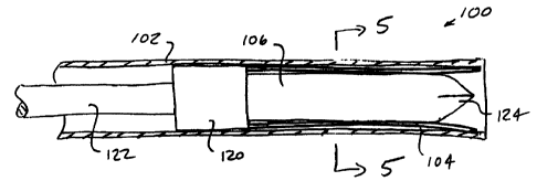
Referring now to Figs. 4-6, a particular electrode
assembly for use in the methods of the present invention will
be described. A probe system 100 includes a cannula 102 and a
plurality of individual electrodes 104 constrained within the
cannula over the outer cylindrical surface of a core
member 106. The cannula 102 is only partly illustrated with a
proximal length broken-off. The entire cannula will typically
have a length in the range from about 5 cm to 30 cm,
preferably from 10 cm to 20 cm, and outer diameter in the
range from 1 mm to 5 mm, preferably from 1.3 mm to 4 mm, and
an inner diameter in the range from 0.7 mm to 4 mm, preferably
from 1 mm to 3.5 mm. The cannula may be formed from metals,
plastics, or the like, and may be electrically active or
inactive within the probe system, depending on the manner in
which electrical energy is to be applied.
The individual electrodes 104 are illustrated as
having rectangular cross-sectional geometries, with preferred
dimensions generally within the ranges set forth above. The
electrodes 104 are resilient and have a spring memory which
causes them to curve along an arcuate path as they are
distally extended from the cannula 102, as shown in Figs. 13-
16 hereinafter.
An annular envelope 110 is defined between the inner
surface of the cannula 102 and the outer surface of core
member 110, as best seen in Figs. 5 and 6. The width of the
annular envelope 110 (defined by the distance between the
outer surface of core 106 and inner surface of cannula 102) as
typically in the range from 0.1 mm to 1 mm, preferably from
0.15 mm to 0.5 mm, and will usually be selected to be slightly
larger than the thickness of the individual electrodes 104 in
the radial direction. In this way, the electrodes are
CA 02303187 2000-03-09
WO 99/15117 PCT/US98/20198
17
constrained and held in generally axially aligned positions
within the cannula 102.
Electrodes 104 are connected at their proximal ends
to a cylindrical block 120 which in turn is secured to the
distal end of a reciprocatable shaft 122. The core 106 is
also secured to the distal end of cylindrical block 120 so
that the core and electrodes move together as the shaft 122 is
advanced distally or retracted proximally relative to the
cannula 102. As the core 106 moves with the electrodes, it
will be appreciated that the core will enter the tissue at the
same time as the electrodes 104. Thus, the core 106 is shown
to have a sharpened distal end 124 to enhance tissue
penetration. The core 106 may be electrically coupled to the
electrodes 104 (in which case it acts as an additional
electrode of the same polarity as electrodes 104) or may be
electrically isolated from the electrodes. When the core is
electrically isolated, it can remain neutral during a
treatment protocol, or alternatively it may be energized in
the opposite polarity and thus act as a return electrode in a
bipolar treatment protocol.
Note that a total of six electrodes are illustrated.
Additional electrodes could be added in the spaces between the
illustrated electrodes, with the maximum number of electrodes
determined by the electrode width and total circumferential
distance available (i.e., the electrodes could be tightly
packed). It would also be possible to add additional
concentric layers of electrodes, although such a design will
generally not be preferred.
As discussed above, the electrosurgical power supply
ES may be a conventional or modified power supply, depending
on the desired implementation of the methods of the present
invention. The methods may be performed manually, i.e. by an
operator manually adjusting the power levels and observing the
power deliveries on a conventional power supply.
Alternatively and preferably, the methods of the present
invention may be implemented using a digital controller which
may be incorporated within the electrosurgical power supply
ES, situated between the electrosurgical power supply and the
CA 02303187 2000-03-09
WO 99/15117 PCTIUS98/20198
18
patient, or which may be interfaced with a properly equipped
power supply. The use of a computer interfaced with a power
supply is illustrated in Fig. 10. The power supply ES will
also usually include a monitoring/control interface. The
computer PC may employ any operating system compatible with
the electrosurgical power supply ES, the computer will
typically be interfaced using a conventional cable. The
methods of the present invention may be delivered to the
personal computer PC and thus to the electrosurgical power
supply ES by programming the computer in any conventional
manner. A floppy disk D or other computer memory component
may be used in order to implement the program within the
computer. Any other manner of delivering computer readable
code and instructions into the computer may also be utilized,
including compact disk, tape, read only memory (ROM), and
delivery of instructions via a modem and/or over the internet.
Referring now to Figs. 7-10, a treatment region TR
within tissue T is located beneath the skin or an organ
surface S of a patient. The treatment region TR may be a
solid tumor or other lesion where it is desired to treat the
tissue by RF hyperthermia. The treatment region TR prior to
treatment is shown in Fig. 7.
In order to introduce an electrode array according
to the method of the present invention, a conventional sheath
and obturator/stylet assembly 300 is introduced through the
skin or organ surface S so that a distal end of the sheath
lies at or within a target site TS within the treatment
region, as shown in Fig. 8. In many cases, the sheath and
obturator/stylet assembly 300 may be introduced percutaneously
directly through the patient's skin. In other cases, however,
it may be desirable to provide an open surgical incision or to
place a trocar through the skin in order to introduce the
stylet to the organ surface S. In either case, the
obturator/stylet 302 is then removed from the sheath 304,
leaving the sheath in place as shown in Fig. 9. The
cannula 102 of probe system 100 may then be introduced through
the lumen of sheath 304 so that a distal end advances from the
sheath into the target region T, also as shown in Fig. 9
CA 02303187 2000-03-09
WO 99/15117 PCTIUS98/20198
19
An alternative placement method would utilize a
cannula which incorporates a thin insulating film covering the
exterior. Thus, the sheath/cannula may be directly inserted
into target tissue without use of a separate sheath.
After the cannula 102 is properly placed, the
shaft 122 will be distally advanced to deploy the
electrodes 104 radially outwardly from the distal end of the
cannula, as shown in Fig. 10. The shaft 122 will be advanced
sufficiently so that the electrodes 104 fully evert in order
to circumscribe substantially the entire treatment region TR.
The core member 106 (Fig. 10) also advances distally into the
tissue along a line which is axially aligned with the
cannula 102.
A connector 140 at the proximal end of shaft 122 may
then be connected to an electrosurgical power supply ES.
Suitable power supplies are available from commercial
suppliers as listed above. A second connecting cable 190
extends from the electrosurgical power supply ES to a
dispersive plate electrode (not shown) on the patient for
monopolar operation.
While the above is a complete description of the
preferred embodiments of the invention, various alternatives,
modifications, and equivalents may be used. Therefore, the
above description should not be taken as limiting the scope of
the invention which is defined by the appended claims.