Note : Les descriptions sont présentées dans la langue officielle dans laquelle elles ont été soumises.
CA 02305648 2000-03-27
WO 99/18244 PCT/US98/18502
METHOD AND APPARATUS FOR INSTALLATION OF
REFRACTORY MATERIAL INTO A METALLURICAL VESSEL
FIELD OF THE INVENTION
The present invention generally relates to a method and apparatus for forming
a
lining on the internal faces of a metallurgical vessel, such as a tundish or a
casting ladle in
order to protect the vessel wall or its permanent refractory lining.
BACKGROUND OF THE INVENTION
Refractory products are often utilized as protective layers to protect the
vessels
that hold and transfer molten metal in metal casting processes such as steel
making. For
example, refractory products may be utilized as protective layers to protect
furnaces,
ladles, and tundishes. The purpose of the protective layer is to protect the
brick, safety
lining, and steel shell of the vessel from steel and slag penetration. By
inhibiting this
penetration, the protective layer prolongs the life of the vessel.
Conventional methods for forming protective layers include installing a
granular
refractory composition on the interior faces of a metallurgical vessel and
heating the
granular refractory composition to solidify and form a protective lining.
The problems associated with installing refractory material in metallurgical
vessels are well-known. Various methods are currently used with various
drawbacks.
For instance, according to one method, a protective layer is applied on the
internal faces
of a metallurgical vessel by spraying a water-based slurry consisting of a
mixture of
refractory materials, fibers and a binder. Although this method proves
satisfactory, it
suffers from the disadvantage of covering the internal faces of the
metallurgical vessel
with a lining containing a considerable quantity of water, which has to be
eliminated by a
long and costly drying operation. A second known method includes installing a
dry
refractory lining composition into a space located between the internal faces
of the
SUBSTITUTE SHEET (RULE 26)
CA 02305648 2000-03-27
WO 99/18244 PCT/US98/18502
metallurgical vessel and a mandrel placed within the vessel. The mandrel can
be
equipped with preheating means and valves through which heat can be applied
which sets
(hardens) the lining composition that has been poured into the space mentioned
above.
Past practices for installing the protective layers have the following
drawbacks:
1. In the first method, the main drawback is that considerable water is
required, thus requiring drying. In addition, this method has the further
drawbacks as
follows:
a. the slurry spraying equipment requires considerable maintenance,
b. the slurry compositions require careful manufacture to meet
specifications, and
c. the installation of the slurry is labor intensive and time consuming.
2. In the second method, although no water is required, considerable
drawbacks still exist as follows:
a. the use of manual labor to hand break 50 to 100 lb. bags of
granular refractory material,
b. the unsafe method of loading bulk sacks of granular refractory
material into a metallurgical vessel,
c. the unsafe method of loading bulk sacks of granular refractory
material into a feed hopper to create a reserve and then dispensing the
granular refractory
material into the metallurgical vessel (i) by a feed chute or funnel or (ii)
by a mechanica~
feeding apparatus,
d. the unsafe method of hanging a bulk sack of granular refractory
material that has a special discharge spout sewn into it over the
metallurgical vessel to
empty the granular refractory material,
e. the unsafe method of hanging bulk containers of granular
refractory material with special outlet discharge hoses over the metallurgical
vessel to
empty the granular refractory material, and
f. the action of filling the gap can cause segregation of coarse and
fine particles resulting in weak areas.
The conventional methods are labor intensive and create unsafe working
SUBSTITUTE SHEET (RULE 26)
CA 02305648 2000-03-27
WO 99/18244 PCT/US98/18502
conditions, especially when working under or near overhead hanging loads. The
past
practices also create a very imitating dusty work environment.
For example, U.S. Patents Nos. 5,302,563 to Rumpeltin et al., and 5,036,029 to
Johnson disclose methods for wet spraying a refractory composition to form a
lining in a
metallurgical vessel.
In an attempt to overcome the disadvantages of installing a dry composition,
U.S.
Patent No. 5,176,873 to Daussan et al. discloses a method that involves the
use of a
movable wall to form a lining on the internal faces of a metallurgical vessel
using a dry
granular refractory material. The method involves positioning the movable wall
into the
metallurgical vessel, introducing the granular refractory material between an
internal face
of the metallurgical vessel and the movable wall, heating the granular
refractory material
to sinter the internal face, transversely displacing the movable wall, and
repeating the
above steps until a lining is complete on the internal faces of the
metallurgical vessel.
Since the lining of Daussan is prepared one portion at a time, different
portions of the
lining set at different times. This results in the development of seams in the
lining. In
particular, the device discussed in Daussan does not permit the development of
a
continuous lining at the corners of the metallurgical vessel and rather
results in seams.
This is due to the fact that the device needs to be displaced from each wall
once the lining
against the wall is made and replaced onto the next wall to begin forming the
lining
against that wall. During this time, the previous wall cools. Once the
subsequent wall is
formed, a seam is formed at the corner between the previous and the subsequent
wall.
There therefore remains a need for better methods and apparatus that are
capable
of forming a refractory lining on the internal faces of a metallurgical vessel
such as a
tundish. The aim of the present invention is to overcome the disadvantages of
known
methods.
SUMMARY OF THE INVENTION
As an aid to understanding, but without being limited thereby, the present
invention is based on the discovery that the addition of a granular refractory
composition
SUBSTITUTE 8HEET (RULE 26)
CA 02305648 2000-03-27
WO 99/18244 PCf/US98/18502
in a single mass results in improved integrity of the resulting refractory
lining in a vess~i
such as a metallurgical vessel. When the granular refractory composition is
added in a
single mass into a gap formed between the metallurgical vessel and a mandrel,
the
turbulence that is created causes a mixing action that tends to reduce any
segregation of
particle sizes in the granular refractory composition that may have been
present. The
mixing action can be further enhanced by use of deflectors, which aid the flow
and
mixing as the granular composition is added into the gap. Furthermore,
although air is
not required for the inventive method, any air in the gap that is displaced by
the granular
composition further aids the mixing thereof. The resulting refractory lining
has a more
homogeneous structure than conventional refractory linings. The improved
homogeneous
structure in the refractory lining of the present invention results in less
"weak zones,"
within the resulting refractory lining. Thus, the refractory lining prepared
according to
the present invention has a longer life expectancy than conventional
refractory linings
prepared by conventional methods even if the same refractory materials are
used.
In addition, the inventive method, which reduces segregation of the particle
sizes,
permits the use of granular compositions having a wider particle size
distribution than
conventional methods.
Accordingly, it is an object of the present invention to provide a method and
apparatus for installing a granular refractory composition into a vessel such
as a
metallurgical vessel.
It is another object of the present invention to provide a method and
apparatus for
installing a granular refractory composition into a metallurgical vessel so as
to form a
continuous lining therein.
It is a further object of the present invention to provide a simple and
efficient
method and apparatus for installing a granular refractory composition into a
metallurgical
vessel.
It is yet a further object of the present invention to provide a method and
apparatus for installing a granular refractory composition into a
metallurgical vessel that
require minimum manual intervention.
It is another object of the present invention to eliminate the health risks
that are
SUBSTITUTE SHEET (RULE 26)
CA 02305648 2000-03-27
WO 99/18244 PCT/US98/18502
associated with the handling of refractory material during installation into a
metallurgical
vessel.
In accordance with the above and other objects, the inventive method comprises
installing a granular refractory composition into a gap formed between a
mandrel and the
interior faces of a metallurgical vessel, wherein the installing includes
positioning the
granular refractory composition over the metallurgical vessel and allowing the
granular
refractory composition to drop into the gap in a single mass. This process can
be carried
out one or more times until installation is complete.
The inventive apparatus may include, for example, a hopper that serves as both
a
transporting and installing device, wherein the hopper is adapted to install a
granular
refractory composition into a gap formed between a mandrel and the interior
faces of a
metallurgical vessel, wherein the installation includes dropping the granular
refractory-
composition into the gap in a single mass. Other apparatus that can be used to
drop
granular refractory composition into a gap formed between a mandrel and a
metallurgical
vessel in a single mass to install a refractory lining would be within the
scope of the
present invention.
The inventive method and apparatus may be used with apparatus such as a
storage
member for storing refractory material reserves; a feeding member for
dispensing the
stored refractory material into the transporting and installing device; a
mandrel member
designed and built to give the proper finished working lining contour in a
metallurgical
vessel; a vibrating member to fiirther reduce the porosity of the lining; and
a heating
member to heat set the refractory material, to ease the installation of
refractory material in
a metallurgical vessel. All of these apparatus are well-known to those skilled
in the art.
The present invention is also directed to the refractory lining that results
from use
of the present inventive method and apparatus. The refractory lining may be
characterized by its more homogeneous structure, as well as by its ability to
withstand
wear during steel processing.
Additional objects and attendant advantages of the present invention will be
set
forth in the description and examples that follow, or may be learned from
practicing the
method or using the apparatus of the present invention. These and other
objects and
SUBSTITUTE SHEET (RULE 26)
CA 02305648 2000-03-27
WO 99/18244 PCT/US98/18502
advantages may be realized and attained by means of the features,
instnamentalities
and/or combinations particularly described herein. It is also to be understood
that the
foregoing general description and the following detailed description are only
exemplary
and explanatory and are not to be viewed as limiting or restricting the
invention as
claimed.
The invention itself, together with further objects and attendant advantages,
will
best be understood by reference to the following detailed description, taken
in
conjunction with the accompanying drawings.
BRIEF DESCRIPTION OF THE DRAWINGS
FIG. 1 is a schematic showing a cross sectional view of one example of a
transporting and installing device for installing a protective lining in
accordance with the
method of the present invention.
FIG. 2 is a schematic showing a fragmentary plan.view of a transporting and
installing device.
FIG. 3 is a schematic showing a cross sectional view of an adapted mandrel
that
may be used as an accessory apparatus with the transporting and installing
device.
FIG. 4 is a schematic showing a cross sectional view of the positioning of the
transporting and installing device over the mandrel and the metallurgical
vessel so as to
allow an amount of the granular refractory composition sufficient to fill a
gap formed
between the mandrel and the metallurgical vessel to drop into the gap in a
single mass.
FIG. 5 is a schematic showing accessory apparatus that may be employed with
t:~e
inventive method and apparatus to ease the installation of the granular
refractory
composition into a metallurgical vessel.
FIG. 6A and FIG. 6B are photographs of refractory lining installed using ( 1 )
a
conventional method (FIG. 6A) and (2) the method of the present invention
(FIG. 6B).
FIG. 7A, FIG. 7B, FIG. 7C and FIG. 7D are schematics that show why
segregation of particle sizes is virtually non-existent in refractory linings
installed using
the method of the present invention.
SUBSTITUTE SHEET (RULE 28)
CA 02305648 2000-03-27
WO 99/18244 PCT/US98/18502
FIG. 8A and FIG. 8B are schematics showing how the segregation of particle
sizes happen when refractory material is installed in a conventional manner.
FIG. 9 is a schematic showing a cross sectional view of a newly installed
working
lining prepared in accordance with the method of the present invention.
FIG. 10 is a schematic showing a heating member cover that mates with the
mandrel member over the metallurgical vessel.
FIG. 11A and FIG. 11B are schematics showing an example of another type of a
valve that can be used in the transporting and installing device of the
invention in the
closed (FIG. 11A) and the opened (FIG. 11B) positions.
FIG. 12 is a schematic showing the use of an air bag as an actuator in a
system to
support and release the granular composition that can be used in the
transporting and
installing device of the invention.
FIG. 13A and FIG. 13B are schematics showing a cross sectional view of a
rotary
valve system that may be used to install one or two or more different granular
compositions that can be used in the transporting and installing device of the
invention.
In the following description, like parts are designated by like reference
numbers
throughout the figures.
DETAILED DESCRIPTION OF THE INVENTION
All patents, patent applications and literatures that may be cited in this
description
are incorporated herein by reference in their entirety.
As a further aid to understanding the present invention, but without being
limited
thereby, it is believed that dropping a granular composition into a gap formed
between a
mandrel and a metallurgical vessel in a single mass creates turbulence that
causes a
mixing action that tends to homogenize any segregation of particle sizes that
may have
been present in the granular composition.
It is to be understood that although the present disclosure is directed to the
installation of a granular refractory composition into a metallurgical vessel,
the inventive
method includes the installation of any type of granular composition into any
type of
SUBSTITUTE SHEET (RULE 26~
CA 02305648 2000-03-27
WO 99/18244 PCT/US98/18502
vessel. It is well-known in the art that a segregated refractory lining, i.e.,
one in which
larger particles and smaller particles are not distributed evenly throughout,
is not as
durable as a homogeneous refractory lining. This is due in part because a
segregated
refractory lining can lead to differential shrinkage which leads to cracking
and total lining
weakness. This, in turn, leads to metal and slag penetration, which damages
the
metallurgical vessel.
The invention involves a method that eases the installation of granular
refractory
compositions, and, in particular, dry vibratable refractory compositions, into
a
metallurgical vessel working lining. The invention also involves apparatus
that permit
the carrying out of the inventive method.
The granular refractory composition may contain one or more of the materials
disclosed in, for example, U.S. Patents Nos. 5,300,144 to Adams, and 5,366,944
to
Rumpeltin et al., the entire contents of which are incorporated herein by
reference. As
discussed in U.S. Patent No. 5,300,144, the dry vibratable granular refractory
composition is substantially dry and free flowing. Thus, although a liquid
component
may be present in the dry vibratable granular refractory composition, the
concentration of
any liquid component must not be so great as to cause the composition to cease
being free
flowing.
Conventional installation practices involve cumbersome, laborious, and safety
compromising techniques. The present invention, in contrast, allows the
granular
refractory composition to be installed by one operator quickly and safely.
This is
possible partly due, for example, to the use of a transporting and installing
device that can
transport the granular refractory composition to the metallurgical vessel and
install the
granular refractory composition into a gap formed between the interior walls
of the
metallurgical vessel and the outer surfaces of a mandrel placed within the
metallurgical
vessel in a single drop. Although this process can be carned out one or more
times until
installation is complete, it is preferred that an amount of granular
refractory composition
sufficient to complete installation is installed in one drop. The ability of
the transporting
and installing device to drop the granular refractory composition into the gap
in a single
mass permits the rapid formation of a continuous refractory lining in the
metallurgical
8
SUBSTITUTE SHEET (RULE 26)
CA 02305648 2000-03-27
WO 99/18244 PCT/US98/18502
vessel.
The method and apparatus of the present invention thus permit a rapid and safe
means for installing a refractory lining into a metallurgical vessel.
The continuous refractory lining of the present invention is advantageous over
conventional refractory linings in that it has greater life expectancy, which
results in less
cost to the user.
The inventive apparatus may be used with the following apparatus to achieve
rapid and effective installation of granular refractory composition into a
metallurgical
vessel:
(1) a storage member for storing granular refractory composition reserves;
(2) a feeding member for dispensing the stored granular refractory
composition into the transporting and installing device;
(3) a reusable mandrel member that may be designed and built to give the
proper finished working lining contour in a metallurgical vessel and that may
be adapted
to aid in the positioning of the transporting and installing device over the
metallurgical
vessel;
(4) a heating member that may be designed and built specifically to fit the
mandrel member and to bake the installed granular refractory composition to
the proper
set; and
(S) a mechanical vibrating member.
The method of the invention permits safer, easier, more economical, and more
predictable installation of refractory linings in metallurgical vessels.
Turning now to the drawings, FIG. 1 is a schematic showing an example of a
transporting and installing device 1 that may be used to achieve the method of
the present
invention. The transporting and installing device 1 comprises a cavity 2
around at least 3
portion of its outer perimeter 3 for holding a granular composition 4 such as
a granular
refractory composition. The granular composition 4 is held within the cavity 2
by one or
more valves 5, which when opened, permit the installation of the granular
composition 4
into a vessel such as a metallurgical vessel (see FIG. 4).
SUBSTfTUTE SHEET (RULE 26)
CA 02305648 2000-03-27
WO 99/18244 PCT/US98/18502
Although the cavity 2 may hold a calculated amount of granular refractory
composition 4 to complete the working lining installation in a single drop,
the amount of
granular refractory composition 4 need not be precisely measured, since if
underfilled,
additional drops may be carried out to complete the installation, and if
overfilled, the
valves 5 will close, thus allowing the use of any overfill to install a second
lining.
The transporting and installing device 1 may also have a lifting device 25
fabricated into the design to facilitate transport to the various stations
during its cycle.
The transporting and installing device 1 holds the 'granular composition 4
with a
simple valve system or the like that is incorporated on all sides. Any type of
valve
system may be employed, including actuators, pneumatics and hydraulic systems.
Each
valve S may be a hinged dump gate. The joints of the hinges may be covered
with a
flexible shield to keep them from contacting the refractory material. This
helps keep the
hinges from jamming. The valve dump gate may be actuated and latched from
outside
the granular composition 4 holding structure. The latching mechanism can be
constructed in any configuration that may need to be incorporated into a
specific
situation. Actuation can be manual or by automated means. The valves 5 are
closed
when being loaded and during transport and opened during installation.
The entire transporting and installing device 1 may be designed to be rigid
and
self supporting. Furthermore, for convenience, the transporting and installing
device 1
may be specially designed to mate to a mandrel member 7 (see FIGS. 3, 4 and 5)
with
minimal effort. This can be done, for example, by having the base b (see FIGS.
1, 4 and
5) of the transporting and installing device 1 be the foundation that mates
the structure to
the mandrel member 7. This may be accomplished by a guidance system that is
incorporated into the base b. The base b would thus mate quickly with minimal
effort
with the top of the mandrel member 7 into mating guide 8 as designed. This
simple
system aids in the positioning of the transporting and installing device 1
over a workiy
lining gap 10 (see FIG. 4). Other apparatus may be used to ensure proper
positioning of
the granular composition over the metallurgical vessel.
The transporting and installing device 1 can hold the proper amount of
granular
composition 4 to install all of the working lining walls of the metallurgical
vessel 9 (see
io
SUBSTITUTE SHEET (RULE 26)
CA 02305648 2000-03-27
WO 99/18244 PG"f/US98/18502
FIG. 4) at one time. The installation time is a fraction compared to
conventional
practices, and requires only one operator. With the transporting and
installing device 1
properly positioned, the installation operator only actuates the drop. This is
not a
laborious or unsafe task, as is the current practice.
The transporting and installing device 1 thus preferably contains guiding
members
6 (see FIGS. 1 and 4), for guiding and positioning the transporting and
installing device; 1
over an adapted mandrel member 7 placed in the metallurgical vessel 9.
Turning now to FIG. 2, which shows a fragmentary plan view of the transporting
and installing device 1. As can be seen from a review of FIG. 2, the cavity 2
is defined
by an inner wall 17 that surrounds the inner perimeter forming the cavity 2;
an outer wall
18 that surrounds the outer perimeter forming the cavity 2; an upper flange 19
that
provides rigidity and structural strength to the transporting and installing
device 1; and
one or more dump gates 20 (or valves S) and one or more deflectors 21 that
form the floor
of the cavity 2, thus forming a seal when the dump gates 20 (or valves S) are
closed. The
one or more dump gates 20 (or valves 5) and the one or more deflectors 21 are
supported
by the inner wall 17 and the outer wall 18. The number of dump gates 20 (or
valves 5)
and deflectors 21 depends upon the shape of the transporting and installing
device 1. In
FIG. 2, there would be four dump gates and four deflectors (not all shown),
one dump
gate 20 (or valve 5) and one deflector 21 for each side of the rectangular-
shaped
transporting and installing device 1. The dump gates 20 (or valves 5) and
deflectors 21
are closed upon transporting the granular composition 4 (see FIGS. 1 and 4)
and opened
upon installing the granular composition 4. When the dump gates 20 (or valves
5) are
opened, the deflectors 21 help center the granular composition 4 as it falls
into the
tundish, thus permitting the granular composition 4 to slide down the inner
wall 17.
More importantly, the deflectors 21 can direct and aid in the flow and the
premixing of
the granular composition 4 as the granular composition 4 falls into the gap 10
(see FIG.
4). The increased mixing is desirable in that it fimther aids the forniation
of a
homogenous lining. The transporting and installing device 1 may also contain
one or
more external mating flanges 22 (or b) and one or more internal mating flanges
23 (or b).
The one or more external mating flanges 22 (or b) aid the mating of the
transporting and
11
SUBSTITUTE SHEET (RULE 26)
CA 02305648 2000-03-27
wo ~nsa~a rcTius9snsso2
installing device 1 to the metallurgical vessel 9 (see FIG. 4) and the one or
more internal
mating flanges 23 (or b) aid in the mating of the transporting and installing
device 1 to
the mandrel member 7 (see FIG. 4). One or more internal webs 24 may also be
used to
further support the inner wall 17, the outer wall 18, the upper flange 19, the
one or more
dump gates 20 (or valves 5) mounted on the outer walls 18 and the one or more
deflectors
21 mounted on the inner walls 17 that form the cavity 2. The transporting and
installing
device 1 may also contain a lifting device 25, for example a lifting eye,
incorporated
therein to aid in the lifting and transport of the transporting and installing
device 1.
Turning now to FIG. 3, which is a schematic showing a mandrel member 7. The
mandrel member 7 may contain complementary guiding members 8 that complement
the
guiding members 6 in the transporting and installing device 1 as shown in FIG.
1 and
FIG. 4 in order to aid in the positioning of the transporting and installing
device 1 over
the metallurgical vessel 9.
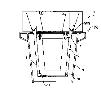
Turning now to FIG. 4, which is a schematic showing the positioning of the
transporting and installing device 1 over the mandrel member 7. As can be seen
in FIG.
4, the complementary guiding members 8 of the mandrel member 7 are adapted to
mate
with the guiding members 6 of the transporting and installing device 1 so as
to allow
rapid positioning of the transporting and installing device 1 above the
metallurgical
vessel 9 with minimal effort. Proper positioning permits rapid installation of
the granular
composition 4 into a gap 10 formed between the mandrel .member 7 and the
interior faces
11 of the metallurgical vessel 9. The transporting and installing device 1 and
the mandrel
member 7 are oriented together with a prepared metallurgical vessel 9 so as to
allow the
granular composition 4 to be installed in seconds. Conventional methods using
conventional apparatus can take 30 minutes or more and generally require more
than one
operator. When the granular composition 4 is finished dropping, a mechanical
vibrating
member 15 (see FIG. 5) may be actuated to settle the granular composition 4 to
a proper
density. Once the granular composition 4 reaches its proper density, a heating
device 14
(see FIG. 5 and FIG. 10), similar to what is now used in the industry, may be
used to
solidify the granular composition 4.
12
sues~urE sHE~r ~RU~ 2s~
CA 02305648 2000-03-27
WO 99/18244 PCT/US98/18502
Turning now to FIG. S, which is a schematic showing apparatus that may be used
with the method and apparatus of the present invention. The apparatus may
include: a
storage member 12, a feeding member 13, a heating member 14, a vibrating
member 15
and a mandrel member 7. The apparatus may be used to complement the inventive
method and, for example, the transporting and installing device 1 to further
aid in the
installation of the granular composition 4 into the metallurgical vessel 9.
As discussed above, the inventive method and apparatus eliminate the need for
hard labor and unsafe working conditions and significantly reduce installation
time and
dust.
Referring to FIG. 5, material that is held in the storage member 12 is fed by
the
feeding member 13 to the transporting and installing device 1. The
transporting and
installing device 1 is transported to the mandrel member 7 that has been
placed into the
prepared metallurgical vessel 9 to be lined. The mandrel member 7 may be self
indexing
into the metallurgical vessel 9 (see FIG. 10, 29 and 6). The transporting and
installing
device 1 then indexes itself into the proper position on top of the mandrel
member 7.
When the metallurgical vessel 9, the mandrel member 7 and the transporting and
installing device 1 have been mated, dump valves 5 (see FIG. 1 and FIG. 4) in
the
transporting and installing device 1 are opened. With the dump valves S
opened, the
granular composition 4 flows in a fluid-like manner into the engineered
working lining
gap 10 (see FIG. 4). The granular composition 4 that has entered the gap 10
(see FIG. 4)
may then be mechanically vibrated using the vibrating member 15 for a set time
to
compact the granular composition 4 to the proper density. With the granular
composition
4 properly installed, the transporting and installing device 1 may be removed
and then a
heating member 14 may be positioned. The heating member 14 may also be indexed
in a
predetermined position (see FIG. 10). The heating member 14 then heat sets the
granular
composition 4 that is in gap 10 (FIG. 4). The heating member 14 may be
programmed to
automatically shut down and then removed after it has finished. Next, a cool
down
period takes place. After the cool down is complete, the mandrel member 7 and
the
transporting and installing device 1, if not earlier removed, may now be
removed from
the metallurgical vessel 9. When the mandrel member 7 and the transporting and
13
SU8ST1TUTE SHEET (RULE 26)
CA 02305648 2000-03-27
WO 99/18244 PCT/US98/18502
installing device 1 have been removed, the metallurgical vessel 9, complete
with the
newly installed working lining 16 (see FIG. 9), is ready for use or for
further preparation.
The storage member 12 (see FIG. 5) permits the storage of the granular
composition 4 near the installation area in a controlled manner. This may be
accomplished by, for example, loading large hoppers or silos by means of bulk
delivery,
which thus provides cost savings to the user. The advantage to this feature is
having the
granular composition 4 readily accessible to be supplied into the feeding
member 13.
This keeps the granular composition 4 in the same area at all times, which is
in contrast ~o
the way granular refractory composition has been inventoried conventionally.
This
permits the filling of the transporting and installing device 1 at the user's
convenience,
thus eliminating the common practice of breaking and loading 50 to 100 lb.
bags of
granular refractory material directly into the metallurgical vessel or a
hopper, which
usually requires more than one person's involvement. It is also possible to
arrange the
loading of the transporting and installing device 1 directly from large 2,000
to 4,000 lb.
bags as is common in the industry.
Turning to FIG. 10, FIG. 10 shows a heating member cover 26 that mates with
the
mandrel member 7. To center the heating member 14 over the metallurgical
vessel (not
shown), the heating member cover 26 can also be designed to mate with the
transporting
and installing device (not shown) of the invention. FIG. 10 shows guiding
members 8
and 27, respectively, that mate the heating member cover 26 with complementary
guiding
members 6 and 28, respectively, on the mandrel member 7 to center the heating
member
14 over the center of the mandrel member 7. The guiding members 27 and 28 are
a
variation, wherein a funnel (27)/cone (28) mating relationship is used. The
heating
member 14 heats mandrel member 7 through a first opening 31 in the heating
member
cover 26. The heat exits thmugh a second opening 32 at the opposite end of the
heating
member cover 26 after travelling through the mandrel member 7. The mandrel
member 7
in FIG. 10 also contains additional directing members 29 and 6, and the like,
to further
aid in the positioning of the mandrel member 7 over the metallurgical vessel
(not shown).
Turning to FIG. 1 lA, FIG. 11B and FIG. I2, which are schematics showing an
example of a valve system that can be used in the transporting and installing
device (not
14
SUBSTITUTE SHEET (RULE 26)
CA 02305648 2000-03-27
WO 99118244 PCT/US98/18502
shown) of the invention. FIG. 12 shows an air bag actuator system 34 that,
when
pressurized, maintains in conjunction with the deflectors 20, the valves S in
the closed
position. The air bag system 34 comprises an air bag 35 attached to support
36, which, in
turn, abuts the valves 5 and a mandrel mating flange 37 of the transporting
and installing
device 1. When pressurized, the air bag 35 holds up the support 36, which in
turn, holds
up the valves 5, thus maintaining closure between the valves 5 and the
deflectors 20 (see
FIG. 1 lA). When pressure is released from the air bag 35, the valves 5 drop,
and the
granular composition 4 is released (see FIG. 11B). The valves 5 thus can be
closed and
opened by inflating and deflating the air bag 3~, respectively.
Turning to FIG. 13A and FIG. 13B, which are schematics showing a cross
sectional view of a rotary valve 37 that may be used in the transporting and
installing
device 1 of the invention. The rotary valve 37 has a passageway 39 that may be
aligned
with one or more holding chambers 38a and 38b for holding one or more granular
compositions (not shown}. When the passageway 39 is lined up with one of the
one or
more holding chambers 38a and 38b, the granular composition contained within
one of
the one or more holding chambers 38a and 38b is released into the
metallurgical vessel
(not shown). Use of the rotary valve 37 permits the application of more than
one type of
granular composition (not shown) into the metallurgical vessel (not shown).
The present invention will be further illustrated in the following non-
limiting
Example and accompanying drawings.
Example
560 pounds of granular material was dropped into a gap formed between a
mandrel and a small Plexiglas scale model of a metallurgical vessel in a
single mass to
form a lining in accordance with the invention. The process took about 3-5
seconds.
This is in contrast to the conventional method of breaking 50-100 Ib. bags and
filling the
gap by hand, wherein only 20-30 Ibs./min. may be installed, thus requiring at
least 15-20
minutes to complete installation.
FIG. 6A and FIG. 6B are photographs of the small Plexiglas scale model showing
refractory lining prepared using (1) a conventional method (FIG. 6A) and (2)
the method
of the present invention (FIG. 6B). As can be seen in FIG. 6A, the lining
prepared using
SUBSTITUTE SHEET (RULE 26)
CA 02305648 2000-03-27
WO 99/18244 PCT/US98/18502
the conventional method, which results in segregation of the particle sizes,
has coarse and
fine layers. As discussed above, the varying layers in an installed lining are
undesirable
because of weak zones.
FIG. 7A, FIG. 7B, FIG. 7C and FIG. 7D are schematics that show why
segregation of particles is virtually non-existent in refractory linings
prepared using the
method and apparatus of the present invention. As shown in FIGS. 7A to 7D, the
granular refractory composition is installed into a gap formed between a
mandrel and a
metallurgical vessel in a single drop. When the material drops into the gap,
the deflectors
21 direct and aid in the flow and premixing of the granular composition 4 (see
FIG. 7C
and FIG. 11B). In addition, any air that may be in the gap is displaced
throughout the
granular composition 4 (see FIG. 7D). The turbulence created by the drop
creates a
mixing action that tends to reduce any segregation of particle sizes that may
have pre-
existed in the granular refractory composition in the transporting and
installing device.
FIG. 8A and FIG. 8B are schematics showing segregation of particles by
particle
size when a granular refractory composition is installed using conventional
methods. As
can be seen in FIG. 8A and FIG. 8B, particles tend to segregate by particle
size due to the
differences in flow properties of large and small particles. As FIG. 8A shows,
because
large particles have more momentum than small particles, they tend to bounce
and roll
down a slope, wherein the small particles are more apt to pile up upon one
another. FIG.
8B shows that the differences in flow properties of the large and small
particles result in
coarse and fine layers in the installed refractory lining.
Although the present invention has been fully described by way of examples
with
reference to the accompanying drawings, it is to be noted that various changes
and
modifications will be apparent to those skilled in the art. It is therefore
intended that the
foregoing detailed description be understood that it is the following claims,
including all
equivalents, which are intended to define the scope of this invention.
Therefore, unless
such changes and modifications depart from the scope of the present invention,
they
should be construed as being included therein.
16
suesTn~ sHeEr tRU~ zs~