Note : Les descriptions sont présentées dans la langue officielle dans laquelle elles ont été soumises.
Reactions of Aromatic Compounds
The present invention relates generally to reactions of aromatic compounds.
In particular, it relates to methods of carrying out electrophillic
substitution reactions
on aromatic compounds using microreactors.
Aromatic compounds undergo a number of electrophillic substitution
reactions, such as nitration and sulphonation, using a variety of reagents. As
an
example, aromatic compounds can be nitrated through the use of nitric acid and
a
catalyst such as sulphuric acid, which are commonly brought into contact with
the
organic compound to be nitrated in a reactor vessel. The product, a
nitroaromatic,
then has to be separated from the resulting mixture using some suitable means
such
as solvent extraction or distillation and the aqueous phase recycled. Such
separation
procedures add considerable cost and complexity to the process. In addition,
undesired by-products may be produced in the reaction, e.g. dinitrobenzene in
the
formation of nitrobenzene. These by-products may result in further
purification of
the product.
Numerous micropreparative and microanalytical methods, and corresponding
equipment, are available to the chemist. For example, D1: L. MESZAROS & 1.
MESZAROS: 'Kontinuerlich arbeitende Fadenreaktoren fiir mikropraparative
Zwecke' FETTE, SEIFEN, ANSTRICHMITTEL., vol. 70, no. 12, 1968, pages 940-
941, XP002095576 discloses a thread reactor and its use in the preparation of
dinitrobenzene and the sulfonation of decylbenzene. The reactants are fed down
two
glass threads which are brought together to a single thread where the
reactants mix
and form an emulsion without any mechanical intervention.
According to the present invention there is provided a method of reacting an
aromatic compound with a reacting agent, the method comprising providing a
first
flow path for the aromatic compound and a second flow path for a reacting
agent, the
reacting agent being immiscible with the aromatic compound and the flow paths
communicating with each other in a region in which the aromatic compound and
the
reacting agent can contact one another, flowing the aromatic compound and the
reacting agent through the first and second flow paths respectively such that,
at least
CA 02307656 2000-04-27
t i r (, . r r t r ,
. 1 l~j 1 i r r i f r t r r I i t . i
in the said region, the flow of the aromatic compound and the reacting agent
is
essentially laminar, and a stable open interface is formed therebetween, at
least the
first flow path in the interface region having a width perpendicular to the
interface in
the range 10-1,000 micrometres, allowing at least a portion of the aromatic
compound to react with the reacting agent and flowing the reacted aromatic
compound and the reacting agent away from said region, the reaction being
carried
out without substantial mixing of the unreacted aromatic compound and the
reacting
agent.
CA 02307656 2000-04-27
CA 02307656 2006-08-14
2
It has been found that the use of a so-called 'microreactor', that is a
reactor having
a flow path dimension perpendicular to the interface of the two liquid phases
of less than
1,000 micrometres, according to the present method, for the nitration of
aromatic compounds
provides unexpected improvements in process control including significant
improvements
in both reaction product yield and purity.
The present method also has advantages over conventional methods, in producing
an
organic product stream which requires no separation from the aqueous reactants
and
products.
The flow rates of the reactants can also be balanced such that a
stoichiometric
reaction occurs, thereby resulting in a more efficient and cost-effective
process which leaves
little or no unreacted reagents which would otherwise reduce the yield of the
main product.
This also reduces the need for extensive purification procedures for the
product.
The flow path carrying the aromatic compound may have a width (defined as
perpendicular to the liquid-liquid interface) in the range 10-1,000
micrometres. Preferably,
the width lies in the range 30-300 micrometres. Most preferably, the width
lies in the range
50-150 micrometres.
The length of the interface region (measured in the direction of the flow) may
typically lie in the range 10 mm to 1 metre. For example, a reactor length of
10 centimetres
has been used to produce high yields. The optimum reactor length for a
particular reaction
will be dependant on the flow rates and reaction kinetics in each case.
Typically, the microreactor used in the present method is the same general
type of
apparatus as disclosed in patent applications WO 96/12541 and WO 96/12540.
Patent applications WO 96/12541 and WO 96/12540 disclose the advantages of
using
microengineered fluid flow paths primarily in solvent extraction processes.
Surprisingly, we
have found that using the apparatus described in WO 96/12541 and WO 96/12540
to carry
out aromatic nitration reactions provides unexpectedly large improvements in
both product
yield and purity.
WO 99/22858 PCT/GB98/03288
3
The improvements in reaction control provided by the present method are
thought to arise from a number of features.
The reacting medium has a high surface area to volume ratio which is thought
to allow very efficient heat dissipation to the walls of the reactor. In the
case of
exothermic reactions, heat generated by the reaction will be carried away from
the
reacting medium thus reducing the tendency of side products to form.
Conversely,
the high surface area to volume ratio may also allow efficient transfer of
heat into the
reacting medium from external sources as required. Thus the microreactor
provides
an efficient means for heat sinking from or heat sourcing to the fluid
reacting region.
The high surface area to volume ratio also provides for a high interfacial
area for
chemical transfer compared with the volume of fluid to be reacted.
The small width of the flow path means that reacting species diffuse over
much shorter distances, particularly over distances associated with the
diffusion
boundary layer width, before they finally react with other reagents than in
conventional reactors.
The use of a flow path with a width perpendicular to the liquid interface
ranging from 10 to 1,000 micrometres allows very accurate control over very
low
flow rates. This fine control over flow rate together with precise control
over
residence time in the reactor provides a highly controllable reacting system
which
may enable highly reactive intermediate products to be formed in high yield.
Such
highly reactive intermediates can be difficult to produce under conventional
reacting
conditions and so may be very valuable. The intermediate may be used in
further
reactions. The intermediate may be removed from the reactor, or additionally
or
alternatively, the reaction may be halted before reaching the final product by
quenching it with a heat sink or through other methods such as the use of
suitable
reagents.
The fine fluidic control of the present method also has the advantage of
enabling the matching of the input reagents to the correct stoichiometry of
the
reaction. This can result in a more efficient and cost-effective process which
leaves
little or no unreacted reagents which would otherwise reduce the yield of the
main
CA 02307656 2000-04-27
WO 99/22858 PCT/GB98/03288
4
product. This also reduces the need for extensive purification procedures for
the
product.
The nitration reaction involves reaction of a first phase comprising an
organic
aromatic compound on a second phase comprising a nitrating agent to produce
two
new phases of different chemical composition to the starting phases. The
aqueous
and organic phases produced are ideally separated such that minimum
contamination
occurs.
Typically, the nitrating agent is a mixture of nitric acid and sulphuric acid.
The reaction is preferably carried out at elevated temperatures, for example,
in the
nitration of benzene, at 60 -140 C, preferably at 90 -120 C..
The mass concentration of sulphuric acid in the sulphuric acid/nitric acid
mixture is typically from 60%-85%, preferably 65%-80% more preferably from
70%-75%. The mass concentration of nitric acid is preferably from 3 lo-5%.
The organic volume is preferably from 5%-20% of the total and more
preferably of the order of 10%.
As indicated above, a preferred reactor length for this nitration reaction is
in
the range 50 m to 1504m, such a length taking into account reaction
performance on
the one hand and pressure drop and blockage factors on the other hand.
Preferred conditions for nitration of aromatic compounds include a sulphuric
acid range of 70-75%, about 3% nitric acid, about 10% volumetric organic flow
and a
temperature of about 100 C. In general the nitric acid content should be
balanced
with the organic content. Below 5% organic may result in instability and above
20%
organic may require excessive quantities of nitric acid, thereby possibly
causing DNP
to increase and the strength of the sulphuric acid to fall to too low a value.
Other examples of this type of reaction include the sulphonation of an
aromatic compound using sulphuric acid as the sulphonating agent. The aromatic
compound is slowly consumed in the reaction yielding a single aqueous phase.
Reactions of the type with which this invention is concerned may be
enhanced by virtue of the short diffusion distances over which the reagents
must
diffuse. Such diffusion distances are characterised by the expression Dt/12
where D is
the diffusion coefficient, t is the time taken for transport of the reagent
before it
CA 02307656 2000-04-27
WO 99/22858 PCT/GB98/03288
reacts with the other reagents and 1 is the length scale over which diffusion
takes
place. For substantial transport (50-100%) of the catalysed reagent, Dt/1,
lies in the
range 0.1-1 (see J. Crank - The Mathematics of Diffusion - Second Edition -
Oxford
University Press, 1975). Typical values of D for liquids lie between 10"10-10-
9 m2/s
5 which, for transport times of around 1 second, require length scales and
thus reactor
dimensions normal to the reactor surface of between 30-100 microns.
The improved reaction control in the present method allows the production of
reagents under highly defined conditions. This control will allow hazardous
reagents
to be produced and controlled such that they are maintained in a safe manner.
The
reduced inventory of the reagents, both within the lead-in flow paths or
microchannels and within the microreactor itself reduces potential risks
associated
with handling hazardous or explosive reagents.
When large quantities of fluid arc required to be reacted, such as in many
practical embodiments, a large number of microreactors may be employed. Since
large numbers of microreactors may be manufactured relatively cheaply, this
provides an efficient way of reacting large quantities of fluid under highly
controlled
conditions. In addition, in such a "scale-up", the reaction conditions in the
microreactors, and hence product distribution, remain unchanged. This is an
advantage in comparison to conventional batch reactors where the distribution
of
products may change as the reaction is scaled up from laboratory-scale to
plant-scale.
Examples of apparatus which can be used in connection with the method of
the present invention will now be described with reference to the accompanying
drawings, in which:-
Figure 1 is a conceptual illustration of a reactor useful in the method of the
present invention;
Figure 2 is a diagrammatic representation of a reactor useful in the method of
the present invention;
Figure 3 shows cross-sections through two channels which may form part of
reactors useful in the method of the present invention;
Figure 4 illustrates a phase splitting at the outlet end of a reactor useful
in the
method for the present invention;
CA 02307656 2000-04-27
CA 02307656 2006-08-14
6
Figure 5 shows a multichannel reactor sheet which may be used in the method of
the
present invention; and
Figure 7 shows a routing sheet which may form part of the same reactor as that
also
partly illustrated in Figure 5.
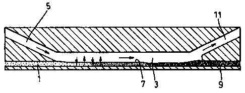
Referring to Figure 1 of the accompanying drawings a reactor which may be used
in
a method of the present invention is shown conceptually. The reactor includes
an input
channel 1 along which, in use, may be flowed an aromatic compound such as
benzene. Input
channel 1 opens into a reactor channel 3 as does a further input channel 5
which is a
somewhat larger cross-section than channel 1. Channel 5 may carry the other
reactant which
may be, for instance, an aqueous mixture of nitric acid and sulphuric acid.
Within reactor channel 3 a laminar flow is established, a stable open
interface 7 being
formed between the organic and aqueous phases. The liquid flow is indicated by
the larger
arrows in Figure 1 and the rapid diffusion across interface 7 is indicated by
the smaller
arrows.
At the end of reactor channel 3 remote from input channels 1 and 5 are located
output
channels 9 and 11. Channel 9 receives the organic output whereas the aqueous
acid output
proceeds along channel 11.
Referring to Figure 2 of the accompanying drawings, there is illustrated more
realistically the structure of a reactor suitable for use in a method of the
present invention.
Organic input is introduced through port 13 and aqueous acid input through
port 15. These
streams are fed through corresponding channels 17 and 19 respectively into the
reactor
channe121 which has a width of 100 m. The organic liquid exits from reactor
channe121
into output channel 23 and out of port 25. The aqueous acid exits from reactor
channel 21
through output channel 27 and port 29.
Figure 3 of the accompanying drawings illustrates two typical reactor channel
cross-sections, channel 31 having a rectangular cross-section and channel 33
being of
semi-circular cross-section. Also shown in Figure 3 are the positions occupied
by the organic
phase 35 and the acid phase 37 in both reactor channels.
Figure 4 of the accompanying drawings illustrates the phase splitting which
takes
place at the output end of reactor channel 35. As shown, the organic phase 37
WO 99/22858 PCT/GB98/03288
7
flows naturally into output channel 39 which is angled as illustrated from
reactor
channel 35. The aqueous acid phase enters output channel 41 which extends
initially
coaxially from reactor channel 35 but then bends as illustrated at 43, the
channel
becoming of larger width at this position.
Figure 5 illustrates a multichannel reactor sheet, in this case containing 61
reactor channels at 45. The size of the sheet is 130mm x 120mm. Finally,
Figure 6
shows a routing sheet for delivering liquid into the reactor channels in
Figure 5. The
sheet size in this case is also 310mm x 120mm.
The reactor throughput for the nitration of benzene is typically of the order
of
0.1 l.s' with an acid flow rate of l.0 l.s'. A typical channel density is of
the order
of I channel per mm width. Sheet thickness obtained using etching techniques
is of
the order of twice the channel width (due to etching from both sides to
produce feed
holes).
For production scale operation of a method according to the present invention
a multichannel reactor might include at least 1,000 channels, perhaps of the
order of
several thousand channels. A degree of parallel processing may be involved in
the
manufacture of such reactors. Among the techniques which can be used in order
to
produce such reactors are the following:-
Chemical etching
Masks are printed onto sheets which contain channel designs. These are then
chemically etched, typically using acid, to produce the finished sheet. Some
intermediate processing may be required, such as UV exposure, before the
etching.
Materials that could be used are metals and glass amongst others.
Embossing
A technique suited to polymers where a single tool is produced (possibly by
non-parallel techniques such as laser ablation or by x-ray lithography). The
tool
embosses out many designs on each sheet in a production run.
To assemble the final unit, the sheets may be bonded into a single block using
the method of diffusion bonding.
Materials which may be used include PTFE (good chemical resistance and
capable of being embossed, stainless steel robust and easy to chemically etch
with
CA 02307656 2000-04-27
WO 99/22858 PCT/GB98/03288
8
reasonable chemical resistance; both machinable and weldable) and glass (easy
to
chemically etch, transparent for visual observation and easily diffusion
bonded).
In a typical multichannel reactor unit the sheet thickness may be similar to
that of the channel width and is typically in the range 50 m to 300 m. The
number
of channels per sheet range from 10 to 1,000 and is typically of the order of
100.
There may be from 10 to 1,000 sheets per block typically of the order of 100.
Accordingly the number of channels per block may be from 100 to 1,000,000 and
is
preferably 1,000 to 100,000.
A 15cm x 15cm x 15cm block containing 1,000 sheets (each 200 m thick) of
100 channels with 100 routing sheets will produce 10ml.s"' of organic output.
Continuous running of such apparatus will produce 864 litres.day' which is
equivalent to about 300 tonnes per year.
Specific embodiments of the invention will now be described in detail by way
of the following Examples only.
Example 1
The formation of nitrobenzene was carried out using a simple reactor with
channel widths perpendicular to the liquid-liquid interface of 10-200 microns.
The
reactor is shown schematically in Figure 2.
Benzene was flowed through port 13, and an aqueous mixture of nitric acid
and sulphuric acid was flowed through port 15. The flow rates of the reactants
were
balanced such that a stoichiometric reaction occurred. Reaction occurred along
the
channel and the product, nitro-benzene, was flowed out of port 25. The
sulphuric
acid and aqueous product was flowed out of port 29. The reactor and flow
conditions
were such that no aqueous phase contaminated the organic product exiting port
25.
No separation of the organic product from the aqueous reactants and products
was
therefore needed. By-products formed were significantly reduced compared to
conventional conditions.
Ideally in this type of reaction only aqueous phase material would leave port
29, but the reactor and conditions could be arranged such that a small
proportion of
organic leaves port 29.
CA 02307656 2000-04-27
WO 99/22858 PCr/GB98/03288
9
Example 2
Benzene nitration was carried out using a 178 m channel, a temperature of
90 C, 78% sulphuric acid and 4.5% nitric acid. The by-product contamination
was
less than 3,000ppm DNB and less than 300ppm DNP.
Benzene nitration carried out with a 178 m channel, a temperature of 90 C,
73% sulphuric acid and 4.5% nitric acid resulted in a by-product contamination
of
less than 500ppm DNB and less than 100ppm DNP.
In a benzene nitration reaction carried out with a 178 m channel, 90 C, 72%
sulphuric acid and 4.5% nitric acid, the time for " complete" conversion was
estimated at 50 seconds. In a similar reaction but carried out with 78%
sulphuric
acid, the time for "complete" conversion was estimated at 25 seconds.
Example 3
Toluene nitration was carried out in a glass reactor of 200 m x 100 m at
100 C with 72% sulphuric acid and 3.0% nitric acid. For a I second residence
time,
43% conversion was obtained. The isomer output was 57% (2-NT), 6% (3-NT) and
37% (4-NT). The time for "conversion" was estimated at 4 seconds.
CA 02307656 2000-04-27