Sélection de la langue

Search

Sommaire du brevet 2311285 

Énoncé de désistement de responsabilité concernant l'information provenant de tiers

Une partie des informations de ce site Web a été fournie par des sources externes. Le gouvernement du Canada n'assume aucune responsabilité concernant la précision, l'actualité ou la fiabilité des informations fournies par les sources externes. Les utilisateurs qui désirent employer cette information devraient consulter directement la source des informations. Le contenu fourni par les sources externes n'est pas assujetti aux exigences sur les langues officielles, la protection des renseignements personnels et l'accessibilité.

Disponibilité de l'Abrégé et des Revendications

L'apparition de différences dans le texte et l'image des Revendications et de l'Abrégé dépend du moment auquel le document est publié. Les textes des Revendications et de l'Abrégé sont affichés :

  • lorsque la demande peut être examinée par le public;
  • lorsque le brevet est émis (délivrance).
(12) Brevet: (11) CA 2311285
(54) Titre français: EMBALLAGE-COQUE POUR DISPOSITIFS MEDICAUX IMPLANTABLES
(54) Titre anglais: BLISTER PACKAGE FOR IMPLANTABLE MEDICAL DEVICES
Statut: Périmé et au-delà du délai pour l’annulation
Données bibliographiques
(51) Classification internationale des brevets (CIB):
  • B65D 75/36 (2006.01)
  • A61F 02/00 (2006.01)
  • B65D 85/08 (2006.01)
(72) Inventeurs :
  • RUDNICK, JAMES J. (Etats-Unis d'Amérique)
  • GOLDEN, MARTIN (Etats-Unis d'Amérique)
(73) Titulaires :
  • MAQUET CARDIOVASCULAR LLC
(71) Demandeurs :
  • MAQUET CARDIOVASCULAR LLC (Etats-Unis d'Amérique)
(74) Agent: PIASETZKI NENNIGER KVAS LLP
(74) Co-agent:
(45) Délivré: 2006-10-24
(86) Date de dépôt PCT: 1998-09-03
(87) Mise à la disponibilité du public: 1999-03-11
Requête d'examen: 2003-08-05
Licence disponible: S.O.
Cédé au domaine public: S.O.
(25) Langue des documents déposés: Anglais

Traité de coopération en matière de brevets (PCT): Oui
(86) Numéro de la demande PCT: PCT/US1998/018409
(87) Numéro de publication internationale PCT: US1998018409
(85) Entrée nationale: 2000-02-29

(30) Données de priorité de la demande:
Numéro de la demande Pays / territoire Date
60/057,983 (Etats-Unis d'Amérique) 1997-09-05

Abrégés

Abrégé français

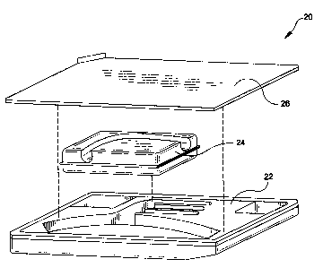
L'invention concerne un ensemble d'emballage pour greffon implantable d'arc aortique en configuration d'implantation. Le greffon pour arc aortique comprend un tube principal et plusieurs ramifications tubulaires partant du tube principal. Une plaquette-coque comporte une dépression destinée à recevoir le tube principal et au moins une ramification tubulaire du greffon. Un insert-coque vient se loger par insertion dans la plaquette-coque. L'insert-coque comprend une dépression formée sur l'une de ses surfaces, dépression qui est destinée à recevoir une autre ramification tubulaire du greffon. L'insert-coque maintient les ramifications tubulaires du greffon portées par la plaquette-coque écartées de la ramification tubulaire portée par l'insert-coque. Un couvercle-coque est disposé amovible sur la plaquette-coque de manière à recouvrir cette dernière et à enfermer le greffon et l'insert-coque à l'intérieur de la plaquette.


Abrégé anglais


A package assembly
supports an implantable aortic
arch graft in configuration for
implantation. The aortic arch graft
includes a main tube and plural
branch tubes extending therefrom.
A blister tray has a blister tray
depression formed therein for
accommodating the main tube and
at least one of the branch tubes
of the graft. A blister insert is
insertably accommodating within
the blister tray. The blister insert
includes a blister insert depression
formed in one surface thereof
for accommodating another of the
branch tubes of the graft. The
blister insert maintains the branch
tubes of the graft, supported by the
blister tray, in spaced positioned
from the branch tube supported by
the blister insert. A blister cover
is removably disposed over the
blister tray for covering the blister
tray and enclosing the graft and
the blister insert within the tray.

Revendications

Note : Les revendications sont présentées dans la langue officielle dans laquelle elles ont été soumises.


WHAT IS CLAIMED IS:
1. A package assembly for supporting an implantable aortic arch graft having a
main tube and a plurality of branch tubes extending therefrom said assembly
comprising:
a blister tray having a blister tray depression formed therein for
accommodating said main tube and at least one of said branch tubes of said
graft;
a blister insert insertably accommodated within said blister tray, said
blister
insert including a first planar surface positionable adjacent said blister
depression of
said blister tray and a second planar surface in spaced opposition to said
first planar
surface, said second surface having formed therein an insert depression for
accommodating therein a further branch tube of said plurality and for
maintaining
spaced separation between said at least one branch tube and said further
branch tube;
and
a blister cover removably disposed over said blister tray for covering said
blister tray and enclosing said graft and said blister insert within said tray
for
maintaining said graft in a sterile environment.
2. A package assembly of claim 1 further including an outer package for
enclosing said covered blister tray and maintaining said covered blister tray
in a sterile
environment.
3. A package assembly of claim 2 wherein said outer package includes:
an outer blister tray for accommodating said covered blister tray; and
11

an outer blister cover removably securable to said outer blister tray for
enclosing said covered blister tray.
4. A package assembly of claim 1 wherein said blister depression of said
blister
tray includes a main tube depression said at least one plural branch tube
depression in
communication with said main tube depression.
5. A package assembly of claim 4 wherein said blister tray includes plural
spaced
apart branch tube depressions in communication with said main tube depression
for
accommodating plural branch tubes of said graft in non-contacting
relationship.
6. A package assembly of claim 5 wherein each of said main tube depression and
said plural branch tube depressions include a curved configuration generally
corresponding to the configuration of said graft during implantation.
7. A package assembly of claim 1 wherein said blister tray includes a
perimetrical rim extending therearound for supporting said blister cover.
8. A package assembly of claim 7 wherein said blister cover is secured to said
perimetrical rim of said blister tray with an adhesive.
9. A package assembly of claim 1 wherein said blister insert is a generally
planar
member being foldable about a central fold line into a folded configuration,
said
12

blister insert defining said opposed first and second planar surfaces in said
folded
configuration.
10. A package assembly of claim 9 wherein said generally planar member of said
blister insert includes a blister cavity formed on each side of said folded
line, said
blister cavity on one side of said fold line forming said first planar surface
and said
blister cavity on said other side of said fold line forming said insert
depression.
13

Description

Note : Les descriptions sont présentées dans la langue officielle dans laquelle elles ont été soumises.


CA 02311285 2000-02-29
WO 99/11195 PCT/US98/18409
BLISTER PACKAGE FOR IMPLANTABLE MEDICAL DEVICES
The present invention relates generally to a blister package used to support a
medical device in a sterile environment. More particularly, the present
invention
relates to a blister package for supporting a vascular graft having complex
shape in a
protective sterile enclosure.
BACKGROUND OF THE INVENT
In the field of medical devices, especially medical devices which are to be
implanted in the body in surgical and nonsurgical procedures, such as
implantable
vascular grafts, it is necessary to provide a sterile protective environment
for such
grafts during shipping and storage prior to use. The use of blister packages
which
support vascular grafts in such a sterile environment is known in the art.
Typical
blister packages include blister trays, which are compression molded plastic
members
having specifically formed cavities or blister depressions formed therein
which
accommodate the vascular graft. These blister trays may be covered with a
blister
cover which is removably adhesively secured to the blister tray to enclose the
vascular
graft in the depression. As such, the interior of the blister package may be
maintained
in a sterile environment so that the vascular graft may be transported to the
surgical
site in a sterile condition. In use, the blister cover is peelably removed
from the tray,
rendering accessible the graft supported therein.

CA 02311285 2000-02-29
WO 99/11195 PCT/US98/18409
In order to provide enhanced sterility, the blister package itself may be
enclosed in a second or outer blister package having a separate removable
sealable
blister cover positioned thereover. The outer blister package may also
maintain a
sterile environment interiorly thereof so that the inner blister package
itself can be
transported in a sterile condition.
For vascular grafts having relatively simple shapes, it is quite easy to form
a
blister package which accommodates the graft in a protective manner. Vascular
grafts
are typically elongate, cylindrical tubes which may include one or more
branches at
one end thereof. It is quite common to form the blister depressions in the
blister tray
to the precise shape of the particular graft which is to be supported therein.
Furthermore, it is desirable to form the shape of the blister depression to
mirror the
shape and configuration of the graft as it is to be used or implanted. Such a
configuration of the blister depression avoids kinking or bending of the graft
during
shipping and storage. The graft will thus be presented to the surgeon, prior
to
implantation, in the shape and configuration in which it is to be used. While
it is
relatively simple to provide blister depressions in a blister tray for grafts
having
simple configurations such as an elongate tube or a tube having one or more
branches
lying in a similar plane, such as is in the case of bifurcated grafts, it is
more difficult
to form a blister depression which will adequately accommodate grafts having
more
complex shapes.
2

CA 02311285 2000-02-29
WO 99/11195 PCT/US98/18409
One such graft is an aortic arch graft 10 shown in Figure 1. Graft 10 includes
an elongate main tube 12 and a plurality of aligned branch tubes 14 extending
from
the main tube 12 in parallel fashion. In certain situations where the aortic
arch graft is
designed to be temporarily connected to external devices, such as for example,
a
heart-lung machine, the graft 10 may include a lateral branch 16 extending
from main
tube 12 at a location spaced from the aligned branches 14.
Blister packages of the prior art have not been able to adequately
accommodate such a complex-shaped aortic arch graft without sacrificing some
degree of protection to the graft during shipment and long term storage.
It is therefore desirable to provide a blister package which is designed to
accommodate a complex graft shape such as an aortic arch graft which protects
the
graft and maintains the graft in a sterile environment.
SUMMARY OF THE INVENTION
It is an object of the present invention to provide an improved package for
supporting an implantable medical device.
It is a further object of the present invention to provide a blister package
for
supporting an aortic arch graft having a main tube and a plurality of branch
tubes
extendins therefrom.

CA 02311285 2000-02-29
WO 99/11195 PCf/US98/18409
It is still a further object of the present invention to provide a blister
package
for supporting an aortic arch graft in a configuration generally ready for
implantation.
In the efficient attainment of these and other objects, the present invention
provides a package assembly for supporting an implantable aortic arch graft
where the
graft includes a main tube and plural branch tubes extending therefrom. The
package
assembly includes a blister tray having a blister depression formed therein.
The
blister depression accommodates the main tube and at least one of the branch
tubes
extending from the graft. A blister insert is insertably accommodated within
the
blister tray. The blister insert includes a first planar surface positionable
adjacent the
blister depression of the blister tray and a second planar surface in spaced
opposition
to the first planar surface. The second planar surface includes a depression
formed
therein for accommodating a further branch tube of the plural branch tubes and
for
maintaining spacial separation between the branch tubes in the blister tray
and the
further branch tube in the blister insert. A blister cover is removably
positioned over
the blister tray for covering the blister tray and enclosing the graft and the
blister
insert within the tray and maintaining the graft in a sterile environment.
As described by way of preferred embodiment herein, the covered blister tray
may be enclosed within an outer package to maintain the covered blister tray
in a
sterile environment. Furthermore, the blister depressions formed in the
blister tray
and the blister insert are preferably of configuration which matches a
configuration of
the aortic arch graft during implantation.
4

CA 02311285 2000-02-29
WO 99/11195 PCT/US98/18409
Figure 1 is a perspective showing of implantable aortic arch graft which may
be used in the package assembly of the present invention.
Figure 2 is an exploded perspective view of the package assembly of the
present invention.
Figures 3 and 4 are top and side plan views respectively, of a blister tray of
the
package assembly of Figure 2.
Figures 5 and 6 are top and side plan views respectively, of a blister insert
of
the package assembly of Figure 1.
Figure 7 shows the blister insert of Figures 5 and 6 in a folded
configuration.
Figure 8 is an exploded side elevational showing of the package assembly of
the present invention enclosed in an outer blister package.
The present invention provides a blister package assembly 20 shown in Figure
2. Assembly 20 includes a blister tray 22, a blister insert 24 and a blister
cover 26.
The blister tray 22 may be formed of suitably formed die cut plastic such as
polyethylene terephthalate (PET), including PETE and PETG, designed to support
the

CA 02311285 2000-02-29
WO 99/11195 PCT/US98/18409
aortic arch graft 10 of Figure 1. Blister insert 24 may also be formed of a
suitably
formed die cut plastic such as PETE and is positioned to be supported over
tray 22.
The blister cover 26 which may be formed .of a polyolefin such as TYVEKTM may
be
positioned over the blister tray to enclose the graft 10 therein. One surface
of blister
cover 26 may be adhesively coated to secure cover 26 to tray 22.
Referring more specifically to Figures 3 and 4, blister tray 22 is generally
an
open-ended rectangular member having a major blister depression 30 formed
therein.
Blister depression 30 takes the shape of the aortic arch graft 10 shown in
Figure 1,
having a central area 31 configured to accommodate the main tube 12 and
aligned
branch areas 31 a, 31 b, and 31 c in communication with central area 31 to
accommodate branch tubes 14. It is noted that blister depression 30 is sized
and
shaped to uniquely accommodate aortic arch graft 12 in a position generally
conforming to that at which it is implanted. The configuration of blister
depression 30
is such that aortic arch graft 10 may be maintained in the blister depression
without
bending or kinking. Also, the blister depression 30 maintains each of the
branches 14
in spaced non-contacting relationship in the blister tray.
In addition to main depression 30 used to accommodate aortic arch graft,
blister tray 22 may also include plural additional depressions 32 which are
provided
for structural stability of the blister tray. Further, blister tray 22 also
includes a
plurality of standoff locations 34 extending from the bottom of the blister
tray. Each
6

CA 02311285 2000-02-29
WO 99/11195 PCT/US98/18409
standoff location 34 together with a perimetrical rim 36 of blister tray 32
provide a
surface to which the adhesive coated blister cover 26 may be applied.
Referring now to Figures 5, 6 and 7, blister insert 24 may be described.
Blister insert 24 is generally a rectangular member having a pair of blister
cavities 44
and 46 formed on each side of a fold line 45. Blister cavity 44 includes a
generally
continuous first planar bottom surface 44a. Blister cavity 46 also includes a
second
planar bottom surface 46a which includes an elongate curved reverse blister
depression 48 formed thereon. Reverse blister depression 48 opens outwardly to
the
planar surface 46a and is configured in a shape to conform to the lateral
branch 16
(Figure 1) when in use. Reverse blister depression 48 is open at each end to
side
surfaces of cavity 46. Blister insert 24 may be folded about a fold line 45
into the
configuration shown generally in Figure 7.
In order to maintain the blister insert in the folded configuration, a
plurality of
cooperating detent members 49 are provided at the corners thereof. Opposed
detent
members 49 interlock when the blister insert 24 is folded about fold line 45
so as to
maintain the blister insert in the folded configuration. In the folded
configuration
shown in Figure 7, blister insert 24 presents bottom surface 44a as a flat
uniformly
smooth member on one side and presents reverse blister depression 48 for the
accommodation of lateral branch 16 on the other side thereof formed by planar
surface
46a. Thus, as shown in Figure 7, reverse blister depression 48 is maintained
in spaced
opposition to planar bottom surface 44a.
7

CA 02311285 2000-02-29
WO 99/11195 PCT/US98/18409
Having described the components of the blister package assembly 20 of the
present invention, its use and operation may be further described with
specific
reference to Figure 1, 2, 3, 5 and 7. Aortic arch graft 10 is positioned
within major
depression 30 of blister tray 22. Main tubular member I2 lies within the
curved
central area 31 of blister depression 30. The aligned extending branches 14
are
positioned in each of the associated branch areas 31 a, 31 b, and 31 c. The
lateral
branch 16 is held away from the blister tray 22 so that blister insert 24, in
the folded
condition shown in Figure 7, may be inserted into blister tray 22. Blister
insert 24 is
inserted in a position where the generally planar bottom surface 44a is
positioned
directly over the branches 14 supported in branch areas 31 a, 31 b and 31 c.
Thus, a
smooth surface is presented directly adjacent the graft branches 14. Such
positioning
of a smooth surface there adjacent reduces any incidence of damage to the
branches
14 when coming in contact with the blister insert 24 during shipment and
storage.
Furthermore, blister insert 24 is positioned within blister tray 22 in a
position where
the fold line 45 is positioned adjacent the central area 31 of blister
depression 30 at the
region of branches 14 and lateral branch 16. In this manner, the smoother
folded side
rather than the die cut edges 25 of the blister insert 24 are positioned
adjacent the
main body 12 and the region of attachment of branches 14 and lateral branch 16
to
graft 10. Again, maintaining the die cut edges 25 of blister insert 24 away
from the
graft 10 during shipment and storage protects the graft and prevents damage
thereto.
Once the graft is supported in blister tray 22 in the manner described above
and the blister insert 24 is properly inserted, the lateral branch 16 is
positioned in
8

CA 02311285 2000-02-29
WO 99/11195 PCT/US98/18409
reverse blister depression 48. The reverse blister depression 48 has a length
sufficient
to fully accommodate a range of lengths of lateral branch 16. So positioned,
the
blister insert 24 spaces and separates the lateral branch 16 from aligned
branches 14 of
graft 10.
Subsequent to such positioning, the blister tray 22 may be covered with
blister
cover 26. An appropriate application of heat and pressure is used to secure
the blister
cover 26 to the blister tray 24. Adhesive engagement is established between
blister
cover 26 and the perimetrical rim 36 of blister tray 22 and the surfaces
provided by
standoffs 34. This prevents the blister cover 26 from becoming inadvertently
dislodged from the blister tray 22 or from separating therefrom. The blister
insert 24
is loosely accommodated in tray 24. This loose accommodation allows blister
tray 24
to "float" within the tray 24. This prevents the insert 24 from being held in
a non-
desirable position. However, the insert 24 is adequately supported in the tray
22 by
cover 26.
As is shown in Figure 8, it is further contemplated, that blister package
assembly 20 may be further enclosed in an outer blister package 50 to enhance
further
protection and sterility. Such outer blister package 50 includes an outer
blister tray 52
which is designed to accommodate blister package assembly 20. An outer blister
cover 54 may be used to fully enclose blister assembly 20 in outer blister
tray 52.
9

CA 02311285 2000-02-29
WO 99/11195 PCT/US98/18409
It can be appreciated that the present invention allows the protective
accommodation of a complex graft configuration having a plurality of branches
where
the branches extend in different planar orientations from the main body of the
graft.
Various changes and modifications can be made to the present invention. It is
intended that all such changes and modifications come within the scope of the
invention as set forth in the following claims.

Dessin représentatif
Une figure unique qui représente un dessin illustrant l'invention.
États administratifs

2024-08-01 : Dans le cadre de la transition vers les Brevets de nouvelle génération (BNG), la base de données sur les brevets canadiens (BDBC) contient désormais un Historique d'événement plus détaillé, qui reproduit le Journal des événements de notre nouvelle solution interne.

Veuillez noter que les événements débutant par « Inactive : » se réfèrent à des événements qui ne sont plus utilisés dans notre nouvelle solution interne.

Pour une meilleure compréhension de l'état de la demande ou brevet qui figure sur cette page, la rubrique Mise en garde , et les descriptions de Brevet , Historique d'événement , Taxes périodiques et Historique des paiements devraient être consultées.

Historique d'événement

Description Date
Le délai pour l'annulation est expiré 2011-09-06
Lettre envoyée 2010-09-03
Lettre envoyée 2009-02-11
Inactive : Transfert individuel 2008-12-09
Accordé par délivrance 2006-10-24
Inactive : Page couverture publiée 2006-10-23
Inactive : Taxe finale reçue 2006-08-03
Préoctroi 2006-08-03
Inactive : CIB de MCD 2006-03-12
Un avis d'acceptation est envoyé 2006-02-14
Lettre envoyée 2006-02-14
Un avis d'acceptation est envoyé 2006-02-14
Inactive : Approuvée aux fins d'acceptation (AFA) 2005-11-02
Lettre envoyée 2003-08-26
Exigences pour une requête d'examen - jugée conforme 2003-08-05
Toutes les exigences pour l'examen - jugée conforme 2003-08-05
Requête d'examen reçue 2003-08-05
Inactive : CIB en 1re position 2000-08-15
Inactive : CIB enlevée 2000-08-15
Inactive : CIB attribuée 2000-08-15
Inactive : Page couverture publiée 2000-08-14
Inactive : CIB en 1re position 2000-08-01
Inactive : Notice - Entrée phase nat. - Pas de RE 2000-07-27
Lettre envoyée 2000-07-27
Demande reçue - PCT 2000-07-21
Inactive : Transfert individuel 2000-05-24
Demande publiée (accessible au public) 1999-03-11

Historique d'abandonnement

Il n'y a pas d'historique d'abandonnement

Taxes périodiques

Le dernier paiement a été reçu le 2006-07-13

Avis : Si le paiement en totalité n'a pas été reçu au plus tard à la date indiquée, une taxe supplémentaire peut être imposée, soit une des taxes suivantes :

  • taxe de rétablissement ;
  • taxe pour paiement en souffrance ; ou
  • taxe additionnelle pour le renversement d'une péremption réputée.

Les taxes sur les brevets sont ajustées au 1er janvier de chaque année. Les montants ci-dessus sont les montants actuels s'ils sont reçus au plus tard le 31 décembre de l'année en cours.
Veuillez vous référer à la page web des taxes sur les brevets de l'OPIC pour voir tous les montants actuels des taxes.

Titulaires au dossier

Les titulaires actuels et antérieures au dossier sont affichés en ordre alphabétique.

Titulaires actuels au dossier
MAQUET CARDIOVASCULAR LLC
Titulaires antérieures au dossier
JAMES J. RUDNICK
MARTIN GOLDEN
Les propriétaires antérieurs qui ne figurent pas dans la liste des « Propriétaires au dossier » apparaîtront dans d'autres documents au dossier.
Documents

Pour visionner les fichiers sélectionnés, entrer le code reCAPTCHA :


Pour visualiser une image, cliquer sur un lien dans la colonne description du document. Pour télécharger l'image (les images), cliquer l'une ou plusieurs cases à cocher dans la première colonne et ensuite cliquer sur le bouton "Télécharger sélection en format PDF (archive Zip)" ou le bouton "Télécharger sélection (en un fichier PDF fusionné)".

Liste des documents de brevet publiés et non publiés sur la BDBC .

Si vous avez des difficultés à accéder au contenu, veuillez communiquer avec le Centre de services à la clientèle au 1-866-997-1936, ou envoyer un courriel au Centre de service à la clientèle de l'OPIC.


Description du
Document 
Date
(aaaa-mm-jj) 
Nombre de pages   Taille de l'image (Ko) 
Dessin représentatif 2000-08-13 1 8
Abrégé 2000-02-28 1 61
Description 2000-02-28 10 344
Revendications 2000-02-28 3 77
Dessins 2000-02-28 6 136
Dessin représentatif 2005-11-17 1 12
Rappel de taxe de maintien due 2000-07-23 1 109
Avis d'entree dans la phase nationale 2000-07-26 1 192
Courtoisie - Certificat d'enregistrement (document(s) connexe(s)) 2000-07-26 1 115
Rappel - requête d'examen 2003-05-05 1 113
Accusé de réception de la requête d'examen 2003-08-25 1 173
Avis du commissaire - Demande jugée acceptable 2006-02-13 1 162
Courtoisie - Certificat d'enregistrement (document(s) connexe(s)) 2009-02-10 1 104
Avis concernant la taxe de maintien 2010-10-17 1 170
PCT 2000-02-28 9 330
Taxes 2003-06-18 1 33
Taxes 2001-06-25 1 36
Taxes 2002-06-20 1 36
Taxes 2000-06-21 1 38
Taxes 2004-06-20 1 35
Taxes 2005-06-21 1 39
Taxes 2006-07-12 1 44
Correspondance 2006-08-02 1 48
Taxes 2008-08-27 1 48