Note : Les descriptions sont présentées dans la langue officielle dans laquelle elles ont été soumises.
CA 02313115 2000-06-08
WO 99/37839 PCTNS98/01247
1
METHOD FOR MAKING A STRONG AND SOFT NONWOVEN WEB
s
~o FIELD OF THE INVENTION
The present invention relates to a method for making a strong and soft
nonwoven
web. Strong and soft materials, such as nonwoven webs are particularly well
suited for
use in disposable absorbent articles such as diapers, incontinence briefs,
training pants,
feminine hygiene garments, and the like, as they are able to be used in
portions of the
i s article where strength and softness can aid in the article's comfort and
overall
performance.
BACKGROUND OF THE INVENTION
Nonwoven webs may be manufactured into products and components of products
2o so inexpensively that the product may be viewed as disposable after only
one or a few
uses. Representatives of such products include diapers, training pants, wipes,
garments,
incontinence briefs, feminine hygiene garments and the like.
Nonwoven webs may be treated to provide the nonwoven web with certain
properties. For example, U.S. Patent No. 5,244,482 issued to Hassenboehler,
Jr. et al. on
zs September 14, 1993 discloses a method for treating a nonwoven web wherein
the
nonwoven web is heated at an elevated temperature and uniaxially drawn to
consolidate
and stabilize the nonwoven web. Such nonwoven webs are noted to exhibit an
increased
elasticity after processing. Such elasticity increase is recognized as being
caused by the
new "memory" instilled by the heating of the nonwoven web. Such drawing and
setting of
3o the nonwoven web by heating at an elevated temperature often causes fiber
embrittlement
and the nonwoven web to exhibit increased gloss. For many applications
involving skin
SUBSTITUTE SHEET (RULE 26)
CA 02313115 2000-06-08
WO 99/37839 PCT/US98/01247
contact. e.g., such as in diaper coverstock. such attributes are contrary to
the desired
cloth-like properties of softness and non-plastic, (low gloss) appearance.
Lastly, the
requirement of heating the nonwoven web to consolidate and stabilize the web
adds to the
complexity and cost of the process.
s U.S. Patent No. 4,981,747 issued to Morman on January 1, 1991, discloses a
"reversibly necked" material. It is taught that the unstabilized necked
material must be
held under high tension on the re-wound roll until such time as the further
heat setting
step is performed to stabilize the material. Such a material will again suffer
the deficits
noted above with respect to preferred skin contact applications, and will
enhance the
io elastic properties of the material rather than the strength and softness of
the material.
U.S. Patent No. 5,226,992 issued to Morman on July 13, 1993, discloses a
method
of producing a composite elastic necked-bonded material. A tensioning force is
applied
to at least one neckable material, such as a neckable nonwoven web, to neck or
consolidate the material. Instead of heating the consolidated nonwoven web,
this patent
~s teaches superposing the tensioned consolidated nonwoven web on an elastic
material and
joining the tensioned consolidated nonwoven web to the elastic material while
the
tensioned consolidated nonwoven web is in a tensioned condition. By joining
the
tensioned consolidated nonwoven web to the elastic material while still in a
tensioned
condition, the nonwoven web is constrained to its' necked dimension.
zo It is an object of the present invention to provide a strong and soft
nonwoven web,
capable of being wound into stable rollstock or festooned form, suitable for
subsequent
conversion or combining operations.
It is also an object of the present invention to provide a post-processing
method
for producing a strong and soft nonwoven web.
~s It is also an object of the present invention to provide a post-processing
method
for producing a strong and soft - nonwoven web that does not require heating
of the
neckable material to elevated temperatures.
As used herein, the temp "elastic", refers to any material which, upon
application
of a biasing force, is stretchable, that is, elongatable, to at least about 60
percent (i.e., to a
SUBSTITUTE SHEET (RULE 26)
_r . .._...._ w . . ...~.._.~....~.._....,.. r_ .._..__
' CA 02313115 2000-06-08
WO 99/37839 PCT/US98/01247
stretched, biased length which is at least about 160 percent of its relaxed
unbiased length),
and which, will recover at least ~~ percent of its elongation upon release of
the stretching,
elonsation force.
As used herein, the term "extensible" refers to any material which, upon
s application of a biasing force, is stretchable, that is, elongatable, to at
least about 60
percent without suffering catastrophic failure (i.e., to a stretched, biased
length which is at
least about 160 percent of its relaxed unbiased length), but does not recover
more than 55
percent of its elongation upon release of the stretching, elongation force.
As used herein, the term "highly extensible" refers to any material which,
upon
~o application of a biasing force, is stretchable, that is, elongatable, to at
least about 100
percent without suffering catastrophic failure (i.e., to a stretched, biased
length which is at
least about 200 percent of its relaxed unbiased length), but does not recover
more than 55
percent of its elongation upon release of the stretching elongation force.
As used herein, the term "stabilized" refers to a material of the present
invention
~s which is capable of being stored in a stable condition in any common or
conventional
web storage manner without the need for further heating or the addition of or
joinder with
other webs to stabilize the material. Such storage means would include for
example, low
tension rolls or festooned material in boxes.
As used herein, the term "nonwoven web", refers to a web that has a structure
of
Zo individual fibers or threads which are interlaid, but not in any regular
repeating manner.
Nonwoven webs have been, in the past, formed by a variety of processes such
as, for
example, meltblowing processes, spunbonding process, and bonded carded web
processes.
As used herein, the term "necked material", refers to any material which has
been
zs constricted in at least one dimension by applying a tensioning force in a
direction that is
perpendicular to the desired direction of neck-down.
As used herein, the term "neckable material", refers to any material which can
be
necked.
SUBSTITUTE SHEET (RULE 26)
CA 02313115 2000-06-08
WO 99/37839 PCT/US98/01247
As used herein, the term "percent neckdown". refers to the ratio determined by
measuring the difference between the un-necked dimension and the stabilized
necked
dimensions of the neckable material in the direction of necking, and then
dividing that
difference by the un-necked dimension of the neckable material, then
multiplying by 100.
s As used herein, the term "composite elastic material", refers to a material
comprising an elastic member joined to a stabilized extensible necked
material. The
elastic member may be joined to the stabilized extensible necked material at
intermittent
points or may be continuously bonded thereto. The joining is accomplished
while the
elastic member and the stabilized extensible necked material are in juxtaposed
~o configuration. The composite elastic material is elastic in a direction
generally parallel to
the direction of neckdown of the stabilized extensible necked material and may
be
stretched in that direction to the breaking point of the stabilized extensible
necked
material. A composite elastic material may include more than two layers.
As used herein, the term "polymer", generally includes, but is not limited to,
i s homopolymers, copolymers, such as, for example, block, graft, random, and
alternating
copolymers. terpolymers, etc. and blends and modifications thereof.
Furthermore, unless
otherwise specifically limited, the term "polymer" shall include all possible
molecular
geometric configurations of the material. These configurations include, but
are not
limited to, isotactic, syndiotactic and random symmetries.
2o As used herein, the term "surface-pathlength" refers to a measurement along
a
topographic surface of the material in question in a specified direction.
SUMMARY OF THE INVENTION
In accordance with the present invention there is provided a method of
producing
zs a stabilized extensible necked nonwoven web comprising the steps of
providing a neckable nonwoven web;
feeding the neckable nonwoven web in a first direction;
SUBSTITUTE SHEET (RULE 26)
r. .___ _.. W_..._.__._.__..~__. _._. ~_..... ,
...._.~......~....._....~._._....._..~.
CA 02313115 2000-06-08
-WO 99/37839 PC'T/US98/01247
applying a tensioning force to the neckable nonwoven web in a direction
parallel
to the first direction to neck the nonwoven web in a direction perpendicular
to the
first direction; and
subjecting the necked nonwoven web to incremental stretching in a direction
s perpendicular to the first direction to provide a strong and soft nonwoven
web.
The method may comprise the additional step of subjecting the nonwoven web to
mechanical stabilization after the nonwoven web has been tensioned in a
direction
parallel to the first direction.
The method may also comprise the additional step of winding the nonwoven web
io onto a take-up roll or festooning the stabilized extensible necked nonwoven
web into box.
The method may also comprise the additional step of joining the nonwoven web
to an elastic member to form a composite elastic material.
The neckable material may be any material that can be necked sufficiently at
room
temperature. Such neckable materials include knitted and loosely woven
fabrics, bonded
~ s carded nonwoven webs, spunbonded nonwoven webs, or meltblown nonwoven
webs.
The neckable material may also have multiple layers such as, for example,
multiple
spunbonded layers and/or multiple meltblown layers or film layers. The
neckable
material may be made of polymers such as for example, polyolefins. Exemplary
polyolefins include polypropylene, polyethylene, ethylene copolymers,
propylene
2o copolymers and blends thereof.
BRIEF DESCRIPTION OF THE DRAWINGS
While the specification concludes with claims particularly pointing out and
distinctly claiming the subject matter which is regarded as forming the
present invention,
2s it is believed that the invention will be better understood from the
following description
which is taken in conjunction with the accompanying drawings in which like
designations
are used to designate substantially identical elements, and in which:
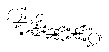
FIG. 1 is schematic illustration of an exemplary process for forming a strong
and
soft nonwoven web of the present invention;
SUBSTIrTUTE SHEET (RULE 26)
CA 02313115 2000-06-08
WO 99/37839 PCT/US98/OI247
- 6
FIG. ? is an enlarged perspective illustration of the stabilizing roller
arrangement;
FIG. 3 is an enlarged perspective illustration of the cross-machine direction
web
enhancement arrangement;
FIG. 4 is a plan view of a spaced-apart pattern of embossments which is not
suitable for setting the necked nonwoven web;
FIG. 5 is a plan view of an embossment pattern of the present invention which
is
suitable for setting the necked nonwoven web;
FIG. 6 is a plan view of another embossment pattern of the present invention
which is suitable for setting the necked nonwoven web; and
co FIG. 7 is a schematic illustration of another exemplary process for forming
a
necked nonwoven web of the present invention.
DETAILED DESCRIPTION OF THE INVENTION
Referring to FIG. 1 there is schematically illustrated at 10 a process for
forming a
~s strong and soft nonwoven web of the present invention.
According to the present invention, a neckable nonwoven web I2 is unwound
from a supply roll 13 and travels in the direction indicated by the arrows
associated
therewith, i.e., in the machine direction or MD or first direction, as the
suppiy roll 13
rotates in the direction indicated by the arrows associated therewith. From
the supply roll
20 13 the neckable nonwoven web 12 passes through a nip 25 of the S-roll
arrangement 26
formed by the stack rollers 28 and 30. The neckable nonwoven web 12 passes
through
the nip 25 of the S-roll arrangement 26 in a reverse-S path as indicated by
the rotation
direction arrows associated with the stack rollers 28 and 30.
The neckable nonwoven web 12 may be formed by known nonwoven extrusion
2s processes. such as, for example, known meltblowing processes or known
spunbonding
processes, and passed directly through the nip 25 without first being stored
on a supply
roll.
From the S-roll arrangement 26 the neckable nonwoven web 12 may optionally
pass through the nip 32 formed by the incremental stretching rollers 34 and 36
of the
SUBSTITUTE SHEET (RULE 26)
r _ ' . _ .., .__..,_.~ ...._.. _.~ _ _
CA 02313115 2000-06-08
WO 99/37839 PCT/US98/01247
_ 7
mechanical stabilization arrangement 38. Preferably, the neckable nonwoven web
12
passes directly to the cross-machine direction web enhancement arrangement 54
from the
S-roll arrangement 26. The optional step of passing through the mechanical
stabilization
arrangement 38 will now be discussed.
s Because the peripheral linear speed of the rollers of the S-roll arrangement
26 is
controlled to be less than the peripheral linear speed of the rollers of the
mechanical
stabilization arrangement 38, the neckable nonwoven web 12 is tensioned
between the S-
roll arrangement 26 and the nip 32 of the incremental stretching rollers 34
and 36 of the
mechanical stabilization arrangement 38. By adjusting the difference in the
speeds of the
i o rollers. the neckable nonwoven web 12 is tensioned so that it necks a
desired amount and
is maintained in such a tensioned, necked condition. The mechanical
stabilization
arrangement 38 provides a stabilized necked nonwoven web.
As the nonwoven web 12 is tensioned between the S-roll arrangement 26 and the
nip 32 of the incremental stretching rollers 34 and 36 tension is applied to
the neckable
i s nonwoven web in a direction parallel to the first direction or parallel to
the machine or
MD direction. The tensioning of the nonwoven web 12 in a direction parallel to
the first
direction causes the nonwoven web to neck in a direction perpendicular to the
first
direction or in a direction parallel to the CD or cross~machine direction.
Entering the S-roll arrangement 26, the nonwoven web 12 has a CD
~o surface-pathlength dimension Z. When tensioned between the S-roll
arrangement 26 and
the nip 32 of the incremental stretching rollers 34 and 36 of the mechanical
stabilization
arrangement 38 the nonwoven web 12 is necked such that its new CD surface-
pathlength
dimension Z' is less than the CD surface-pathlength dimension Z. CD surface-
pathlength
dimension Z' is preferably less than about 75% of CD surface-pathlength
dimension Z,
Zs more preferably less than about 50% of CD surface-pathlength dimension Z,
and most
preferably less than about 30% of CD surface-pathlength dimension Z. For
example, the
nonwoven web 12 having a CD surface-pathlength dimension Z of 10 inches may be
necked to have a CD surface-pathlength dimension Z' of 5 inches which is 50%
of the
CD surface-pathlength dimension Z of 10 inches.
SU9STITU~'E SHEET (RULE 26)
CA 02313115 2000-06-08
WO 99/37839 PCT/US98/01247
8
Other methods of tensioning the neckable nonwoven web 12 may be used such as,
for example, tenter frames.
The neckabie nonwoven web 12 may be extensible. elastic, or nonelastic
nonwoven material. The neckable nonwoven web 12 may be a spunbonded web, a
meltblown web, or a bonded carded web. If the neckable nonwoven web is a web
of
meltblown fibers, it may include meltblown microfibers. The neckable nonwoven
web 12
may be made of fiber forming polymers such as, for example, polyolefins.
Exemplary
polyolefins include one or more of polypropylene, polyethylene, ethylene
copolymers,
propylene copolymers, and butene copolymers.
~o In one embodiment of the present invention, the neckable nonwoven web 12
may
be a multilayer material having, for example, at least one layer of a
spunbonded web
joined to at Ieast one layer of a meltbIown web, a bonded carded web or other
suitable
material. Alternatively, the neckable nonwoven web 12 may be a single layer of
material
such as, for example, a spunbonded web, a meltblown web, or a bonded carded
web.
~s The neckable nonwoven web 12 may also be a composite material made of a
mixture of two or more different fibers or a mixture of fibers and particles.
Such
mixtures may be formed by adding fibers and/or particulates to the gas stream
in which
the meltblown fibers are carried so that an intimate entangled commingling of
meltblown
fibers and other materials, e.g., wood pulp, staple fibers and particulates
such as, for
~o example, hydrocolloidal (hydrogel) particles commonly referred to as
superabsorbent
materials, occurs prior to collection of the meitblown fibers upon a
collecting device to
form a coherent web of randomly dispersed meltblown fibers and other
materials.
The nonwoven web of fibers should be joined by bonding to form a coherent web
structure which is able to withstand necking. Suitable bonding techniques
include, but
zs are not limited to, chemical bonding, thermobonding, such as point
calendering,
hydroentangling, and needling.
FIG. 2 is an enlarged perspective illustration of a preferred embodiment of
the
mechanical stabilization arrangement 38 employing opposed pressure applicators
having
three-dimensional surfaces which at least to a degree are complimentary to one
another.
SUBSTITUTE SHEET RULE 26
r -__~...__ ~ . _ . . . . .,
CA 02313115 2000-06-08
w0 99/37839 PCT/US98/01247
- 9
The mechanical stabilization arrangement 38 shown in FIG. 2 comprises
incremental
stretching rollers 34 and 36. The neckable nonwoven web 12 passes through the
nip 32
formed by incremental stretching rollers 34 and 36 as the incremental
stretching rollers
rotate in the direction indicated by the arrows associated therewith.
Uppermost
s incremental stretching roller 34 comprises a plurality of teeth 40 and
corresponding
grooves 41 which extend about the entire circumference of roller 34. Lowermost
incremental stretching roller 36 comprises a plurality of teeth 42 and
corresponding
grooves 43 which extend about the entire circumference of roller 36. The teeth
40 on
roller 34 intermesh with or engage the grooves 43 on roller 36, while the
teeth 42 on
io roller 36 intermesh with or engage the grooves 41 on roller 34.
The teeth 40 and 42 on rollers 34 and 36, respectively, extend in a direction
substantially perpendicular to the first direction of the neckable nonwoven
web 12 or in a
direction substantially parallel to the width of the neckable nonwoven web 12.
That is,
teeth 40 and 42 extend in a direction parallel to the cross-machine or CD
direction. The
~s incremental stretching rollers 34 and 36 incrementally stretch the necked
web in a
direction generally perpendicular to the necked direction, i.e., in a
direction parallel to the
first direction, thereby stabilizing the necked nonwoven web I2 such that it
remains in its
necked condition after passing through the incremental stretching rollers 34
and 36 and
the tension on the necked nonwoven web is released. By stabilizing the necked
2o nonwoven web, the necked nonwoven web substantially maintains its necked
dimension
without returning to its precursor dimension.
After being stabilized by passing through the incremental stretching rollers
34 and
36, the stabilized necked nonwoven web 12 includes a plurality of stabilizing
embossments 44. Stabilizing embossments 44 extend in a substantially linear
direction
2s parallel to one another across the entire width of the stabilized necked
nonwoven web 12.
The stabilizing embossments 44 are shown to be extending in a direction
substantially
parallel to the CD or cross-machine direction. As seen in FIG. 2, each
stabilizing
embossment extends across the stabilized necked nonwoven web 12 from one edge
to the
other edge. This is important as this sets the fibers across the entire width
of the web
SUBSTITUTE SHEET (RULE 26)
CA 02313115 2000-06-08
-WO 99137839 PCT/US98/01247
- 10
thereby stabilizing the web. If the stabilizing embossments 44 did not extend
entirelv
across the neckable nonwoven web 12, the portion of the neckable nonwoven web
that is
not embossed would return to its precursor width. For example, a spaced apart
pattern of
embossments such as shown in Figure 4, would not effectively set the nonwoven
web.
The portions of the nonwoven web between the individual embossments would not
be set,
and therefore, would allow the nonwoven web to return to its precursor
dimension.
The incremental stretching rollers 34 and 36 may include any number of teeth
and
grooves to provide the desired stabilization in the nonwoven web. In addition,
the teeth
and grooves may be nonlinear, such as for example, curved, sinusoidal, zig-
zag, etc. The
io size and amount of engagement of the teeth and grooves on the incremental
stretching
rollers 34 and 36 may be of any desired dimension. In addition, the teeth and
grooves
may extend in a direction other than perpendicular to the travel direction of
the neckable
web. For example, the teeth and grooves may extend at an angle to the CD
direction, but
preferably not parallel to the MD or machine direction, as this type of
incremental
is stretching would tend to expand the width of the web, thus defeating the
purpose of the
necking operation.
Either directly from the S-roll arrangement 26 or from the optional mechanical
stabilization arrangement 38, the nonwoven web 12 passes to the cross-machine
direction
web enhancement arrangement 54.
zo FIG. 3 is an enlarged perspective illustration of a preferred embodiment of
the
cross-machine direction web enhancement arrangement 54 employing opposed
pressure
applicators having three-dimensional surfaces which at least to a degree are
complimentary to one another. The cross-machine direction web enhancement
arrangement 54 shown in FIG. 3 comprises incremental stretching rollers 51 and
52. The
~s nonwoven web 12 passes through the nip 50 formed by incremental stretching
rollers ~ 1
and 52 as the incremental stretching rollers rotate in the direction indicated
by the arrows
associated therewith. Uppermost incremental stretching roller 51 comprises a
plurality of
teeth 58 and corresponding grooves 59 which extend about the entire
circumference of
roller 51. Lowermost incremental stretching roller 52 comprises a plurality of
teeth 60
SUBSTITUTE SHEET (RULE 26j
~..~ ... ... ___.~._-_..__._._ , ~.. w~...~......~._.._ .,
CA 02313115 2000-06-08
WO 99/37839 PCT/U598/01247
and corresponding grooves 61 which extend about the entire circumference of
roller 52.
The teeth 58 on roller 51 intermesh with or engage the grooves 61 on roller
52, while the
teeth 60 on roller 52 intermesh with or engage the grooves 59 on roller 51.
The teeth 58 and 60 on rollers 51 and 52, respectively, extend in a direction
s substantially parallel to the travel direction of the nonwoven web 12 or in
a direction
substantially perpendicular to the width of the nonwoven web 12. That is.
teeth 58 and
60 extend in a direction parallel to the machine, MD or first direction. The
incremental
stretching rollers 51 and 52 incrementally stretch the nonwoven web in a
direction
generally perpendicular to the first or machine direction thereby causing the
fibers of the
~o nonwoven web to be oriented, at least to a degree, in the cross-machine or
CD direction
or perpendicular to the first direction. In addition to orienting the
individual fibers of the
nonwoven web in CD direction the surface-pathlength of the nonwoven web as
measured
in the CD direction or perpendicular to the first direction increases. As the
nonwoven
web 12 exits the cross-machine direction web enhancement arrangement 54 the
o nowvoven web 12 includes a plurality of rugosities 62. The rugosities 62
provide the
nonwoven web 12 with its increased surface-pathlength as compared to the
surface-
pathlength of the nonwoven web 12 prior to entering the cross-machine
direction web
enhancement arrangement 54.
As can be seen in FIG. 3, prior to entering the nip 50 of the cross-machine
Zo direction web enhancement arrangement 54, the nonwoven web 12 has a CD
surface-pathlength dimension Z'. After being subjected to the incremental
stretching
rollers 51 and 52 the nonwoven web has a plurality of rugosities 62 which
provide the
nonwoven web 12 with a new CD surface-pathlength dimension Z" which is greater
than
CD surface-pathlength dimension Z'. CD surface-pathlength dimension Z" is
preferably
~s at least about 10% greater than CD surface-pathlength dimension Z', more
preferably at
least about 20% greater than CD surface-pathlength dimension Z', and most
preferably at
least about 30% greater than CD surface-pathlength dimension Z'. CD surface-
pathlength dimension Z" may be as much as about 200% greater than dimension Z'
or
more without subjecting the nonwoven web to catastrophic failure.
SUBSTITUTE SHEET (RULE 26)
CA 02313115 2000-06-08
WO 99/37839 PCT/US98/01247
12
The method for determining the surface-pathlength of the nonwoven web can be
found in the Test Methods section set forth in subsequent portions of the
present
specification.
The incremental stretching rollers ~ l and 52 may include any number of teeth
and
_ grooves as desired. In addition, the teeth and grooves may be nonlinear,
such as for
example, curved, sinusoidal, zig-zag, etc. The size and amount of engagement
of teeth
and grooves on incremental stretching rollers 51 and 52 may be of any desired
dimension.
The nonwoven web is both strong and soft after having passed through the cross-
machine direction web enhancement arrangement. Because the nonwoven web is
both
~o strong and soft it is particularly well suited for use in disposable
absorbent articles such as
diapers. incontinent briefs, training pants, feminine hygiene garments, and
the like, as it is
able to be used in portions of the article where high strength and softness
can add to the
articles overall performance.
Referring now to FIG. 1, after the neckable nonwoven web 12 passes through the
n cross-machine direction web enhancement arrangement 54 it is wound up on
take-up roll
50. Alternatively, the neckable nonwoven web 12 may be festooned into a box
using
conventional festooning equipment.
Conventional drive means and other conventional devices which may be utilized
in conjunction with the apparatus of FIG. 1 are well known and, for purposes
of clarity.
2o have not been illustrated in the schematic view of FIG. 1.
In addition to incremental stretching, there are other suitable methods for
mechanically stabilizing the necked nonwoven web. These methods include
crimping,
and/or creping rollers. Another suitable method includes passing the necked
nonwoven
web through the nip of a pair of smooth rollers. The nip pressure and/or
roller
zs enga.gements of such stabilizing rollers are set to provide the desired
degree of
stabilization to the necked web.
FIG. ~ is a plan view of another suitable embossment pattern for stabilizing
the
neckable nonwoven web. The pattern includes a plurality of linear embossments
210
extending continuously across the entire width of the web 205 in a direction
generally
SUBSTITUTE SHEET (RULE 26)
~..__.....,~.. ~_........ _._~~.._.~ .__._... , _...... _......_ .._.. ...
CA 02313115 2000-06-08
WO 99/37839 PCT/US98/01247
- I3
parallel to the cross-machine direction. The pattern also includes a plurality
of linear
embossments 212 extending continuously across the entire width of the web 205
at an
angle to the cross-machine direction and at an angle to the embossments 2I0.
The web
205 also includes a plurality of linear embossments 214 extending continuously
across
s the entire width of the web 205 at an angle to the cross-machine direction
and at an angle
to the embossments 210 and 212. The embossments 212 and 214 may extend at any
angle to one another and to the embossments 210.
FIG. 6 is a plan view of another embossment pattern for stabilizing the
neckable
nonwoven web. The pattern includes a plurality of linear embossments 222
extending
~o continuously across the entire width of the web 220 at an angle to the
cross-machine
direction. The web 220 also includes a plurality of linear embossments 224
extending
continuously across the entire width of the web 220 at an angle to the cross-
machine
direction and at an angle to the embossments 222. The embossments 222 and 224
are
preferably aligned perpendicular to one another. However, other angles between
the
~s linear embossments 222 and 224 may also be employed.
The embossment pattern of FIGS. 5 and 6, is provided by feeding the necked
nonwoven web through a nip formed by a pair of patterned compression rollers.
Each
roller comprises a series of raised surfaces, similar to the teeth 40 and 42
on rollers 34 and
36, respectively. The raised surfaces on each of the rollers are complimentary
and engage
zo one another and compress the necked nonwoven web providing the embossment
pattern
shown in FIGS. 5 and 6. The compression provided by the patterned compression
rollers
sets the individual fibers to stabilize the web in its necked condition.
Alternatively, the patterned compression rollers may comprise a pattern roller
having a pattern of raised surfaces and an anvil roller having a smooth
surface. The
2s raised surfaces on the pattern roller compress the necked nonwoven web
against the anvil
roller to provide the embossment pattern shown in FIGS. 5 and 6.
'The nonwoven web may later be joined to an elastic member to form a composite
elastic material. The nonwoven web and the elastic member may be joined to one
another
either intermittently or substantially continuously along at least a portion
of their
SUBSTITUTE SHEET (RULE 26)
CA 02313115 2000-06-08
WO 99/37839 PCTNS98/01247
- la
coextensive surfaces while the elastic member is in either a tensioned or an
untensioned
condition. The nonwoven web may be joined to an elastic member after having
been
removed from a roll. such as take-up roll 50, or may be joined to an elastic
member after
having been immediately subjected to mechanical stabilization.
The elastic member may be made from any suitable elastic material. Generally,
any suitable elastomeric fiber forming resins or blends containing the same
may be
utilized for the nonwoven webs of elastomeric fibers and any suitable
elastomeric film
forming resins or blends containing the same may be utilized for the
elastomeric films of
the invention. For example, the elastic member may be an elastomeric film made
from
io block copolymers having the general formula A-B-A' where A and A' are each
a
thermoplastic polymer endblock which contains a styrenic moiety such as a
poly(vinyi
arene) and where B is an elastomeric polymer midblock such as a conjugated
diene or a
lower alkene polymer. Other exemplary elastomeric films which may be used to
form the
elastic sheet include polyurethane elastomeric materials such as, for example,
those
is available under the trademark ESTANE from B.F. Goodrich & Company,
polyamide
elastomeric materials such as, for example, those available under the
trademark PEBAX
from the Rilsan Company, and polyester elastomeric materials such as, for
example, those
available under the trade designation Hytrel from E. I. DuPont De Nemours &
Company.
A polyolefin may also be blended with the elastomeric polymer to improve the
2o processability of the composition. The polyolefin must be one which, when
blended and
subjected to an appropriate combination of elevated pressure and elevated
temperature
conditions, is extrudable, in blended form, with the elastomeric polymer.
Useful blending
polyolefin materials include, for example, polyethylene, polypropylene and
polybutene,
including ethylene copolymers, polypropylene copolymers, and butene
copolymers.
~s T'he elastic member may also be a pressure sensitive elastomeric adhesive
sheet.
For example, the elastic material itself may be tacky or, alternatively, a
compatible
tackifying resin may be added to the extrudable elastomeric compositions
described
above to provide an elastomeric sheet that can act as a pressure sensitive
adhesive, e.g., to
bond the elastomeric sheet to a tensioned. necked nonelastic web. The elastic
sheet may
SUBSTITUTE SHEET (RULE 26)
_..._.._._-_.____ ... _ . ~.-.._.__..___.... , _ ._ .... _..~_.__..._.- ...
CA 02313115 2000-06-08
WO 99/37839 PCT/US98/01247
- 15
also be a multilayer material that may include two or more individual coherent
webs or
films. Additionally, the elastomeric sheet may be a multilayer material in
which one or
more of the layers contain a mixture of elastic and nonelastic fibers or
particles.
Other suitable elastomeric materials for use as the elastic member include
"live"
s synthetic or natural rubber including heat shrinkable elastomeric films,
formed
elastomeric scrim, elastomeric foams, or the like. In an especially preferred
embodiment,
the elastic member comprises an elastomeric scrim available from Conwed
Plastics.
Referring now to FIG. 7, there is schematically illustrated another process
100 for
forming a strong and soft nonwoven web of the present invention.
io A neckable nonwoven web 102 is unwound from a supply roll 103 and travels
in
the direction indicated by the arrows associated therewith, i.e., in the
machine or first
direction, as the supply roll 103 rotates in the direction indicated by the
arrows associated
therewith. From the supply roll 103 the neckable nonwoven web 102 passes
through the
nip 125 of the S-roll arrangement 126 formed by the stack rollers 128 and 130.
is The neckable nonwoven web 102 may be formed by known nonwoven extrusion
processes, such as, for example, known meltblowing processes or known
spunbonding
processes, and passed directly through the nip 104 without first being stored
on a supply
roll.
The neckable nonwoven web 102 passes through the nip 125 of the S-roll
zo arrangement 126 in a reverse-S path as indicated by the rotation direction
arrows
associated with the stack rollers 128 and 130. From the S-roll arrangement
126, the
neckable nonwoven web 102 passes through the pressure nip 145 formed by
pressure
roller arrangement 140 comprised of pressure rollers 142 and 144. Because the
peripheral
linear speed of the rollers of the S-roll arrangement 126 is controlled to be
less than the
zs peripheral linear speed of the rollers of the pressure roll arrangement
140, the neckable
nonwoven web 102 is tensioned between the S-roll arrangement 126 and the
pressure nip
of the pressure roll arrangement 140. By adjusting the difference in the
speeds of the
rollers, the neckable nonwoven web 102 is tensioned so that it necks a desired
amount
and is maintained in such a tensioned, necked condition. From the pressure
roller
SUBST11TUTE SHEET (RULE 26)
CA 02313115 2000-06-08
WO 99/37839 PCT/US98/01247
- I6
arrangement 140 the necked nonwoven web 102 may optionally pass through the
nip 151
formed by the mechanical stabilization arrangement 1 ~2 comprised of
incremental
stretching rollers 153 and 154 or may pass directly to the nip 164 of the
cross-machine
direction web enhancement arrangement 167. A more detailed description of a
suitable
s mechanical stabilization arrangement is provided above and is shown in FIG.
2. The
cross-machine direction web enhancement arrangement 167 employs opposed
pressure
applicators having three-dimensional surfaces which at least to a degree are
complimentary to one another. The cross-machine direction web enhancement
arrangement 167 comprises incremental stretching rollers 165 and 166. A more
detailed
io description of the cross-machine direction web enhancement arrangement
comprising
incremental stretching rollers is provided above and is shown in FIG. 3. After
leaving the
cross-machine direction web enhancement arrangement 167 the nonwoven web 102
is
wound up on take-up roil I70. Alternatively, the nonwoven web 102 may be
festooned
into a box using conventional equipment.
~s Conventional drive means and other conventional devices which may be
utilized
in conjunction with the apparatus of FIG. 7 are well known and, for purposes
of clarity,
have not been illustrated in the schematic view of FIG. 7.
Test Methods
zo
Surface-pathlength measurements of nonwoven webs are to be determined by
analyzing the nonwoven webs by means of microscopic image analysis methods.
The sample to be measured is cut and separated from nonwoven web. An
unstrained sample length of one-half inch is to be "gauge marked"
perpendicular to the
~s "measured edge" while attached to the web. and then accurately cut and
removed from the
web.
Measurement samples are then mounted onto the long-edge of a microscopic glass
slide. The "measured edge" is to extend slightly (approximately 1 mm) outward
from the
slide edge. A thin layer of pressure-sensitive adhesive is applied to the
glass face-edge to
SUBSTITUTE SHEET (RULE 26)
r. .
CA 02313115 2000-06-08
WO 99/37839 PCT/US98/01247
- 17
provide a suitable sample support means. For a sample having deep rugosities
it may be
necessary to gently extend the sample (without imposing significant force) to
facilitate
contact and attachment of the sample to the slide edge. This allows improved
edge
identification during image analysis and avoids possible "crumpled" edge
portions that
require additional interpretation analysis.
Images of each sample are to be obtained as "measured edge" views taken with
the support slide "edge on" using suitable microscopic measuring means of
sufficient
quality and magnification. Data is obtained using the following equipment;
Keyence VH-
6100 (20x Lens) video unit, with video-image prints made with a Sony Video
printer
io Mavigraph unit. Video prints are image-scanned with a Hewlett Packard
ScanJet IIP
scanner. Image analysis is on a Macintosh IICi computer utilizing the software
NIH
MAC Image version 1.45.
Using this equipment, a calibration image initially taken of a grid scale
length of
.500" with .005" increment-marks to be used for calibration setting of the
computer image
~ s analysis program. All samples to be measured are then video-imaged and
video-image
printed. Next, all video-prints are image-scanned at 100 dpi (256-level gray
scale) into a
suitable Mac image-file format. Finally, each image-file (including
calibration file) is
analyzed utilizing Mac Image 1.45 computer program. All samples are measured
with
freehand line-measurement tool selected. Samples are measured on both side-
edges and
zo the lengths are recorded. Thin samples require only one side-edge to be
measured. Thick
samples are measured on both side-edges. Length measurement tracings are to be
made
along the full gauge length of a cut sample. In some cases multiple (partially
overlapping) images may be required to cover the entire cut sample. In these
cases, select
characteristic features common to both overlapping-images and utilize as
"markers" to
is permit image length readings to adjoin but not overlap.
The final determination of surface-pathlength is obtained by averaging the
lengths
of five (S) separate 1/2" gauge-samples of each region. Each gauge-sample
"surface-
pathlength" is to be the average of both side-edge surface-pathlengths.
SUBSTITUTE SHEET (RULE 26)
CA 02313115 2000-06-08
WO 99/37839 PCT/US98/01247
- 18
While the test method described above is useful for many of the webs of the
present invention it is recognized that the test method may have to be
modified to
accommodate some webs.
While particular embodiments of the present invention have been illustrated
and
s described, it would be obvious to those skilled in the art that various
other changes and
modifications can be made without departing from the spirit and scope of the
invention.
It is therefore intended to cover in the appended claims all such changes and
modifications that are within the scope of this invention.
io
SUBSTITUTE SHEET (RULE 26)
~....._ __ _ __.._.._