Sélection de la langue

Search

Sommaire du brevet 2318548 

Énoncé de désistement de responsabilité concernant l'information provenant de tiers

Une partie des informations de ce site Web a été fournie par des sources externes. Le gouvernement du Canada n'assume aucune responsabilité concernant la précision, l'actualité ou la fiabilité des informations fournies par les sources externes. Les utilisateurs qui désirent employer cette information devraient consulter directement la source des informations. Le contenu fourni par les sources externes n'est pas assujetti aux exigences sur les langues officielles, la protection des renseignements personnels et l'accessibilité.

Disponibilité de l'Abrégé et des Revendications

L'apparition de différences dans le texte et l'image des Revendications et de l'Abrégé dépend du moment auquel le document est publié. Les textes des Revendications et de l'Abrégé sont affichés :

  • lorsque la demande peut être examinée par le public;
  • lorsque le brevet est émis (délivrance).
(12) Demande de brevet: (11) CA 2318548
(54) Titre français: PROCEDE ET DISPOSITIF POUR REALISER UN GRAND NOMBRE D'ESSAIS BIOLOGIQUES/CHIMIQUES IDENTIQUES A UNE PETITE ECHELLE
(54) Titre anglais: METHOD AND DEVICE FOR CONDUCTING A LARGE NUMBER OF IDENTICAL BIOLOGICAL/CHEMICAL TESTS ON THE MICROSCALE
Statut: Réputée abandonnée et au-delà du délai pour le rétablissement - en attente de la réponse à l’avis de communication rejetée
Données bibliographiques
Abrégés

Abrégé français

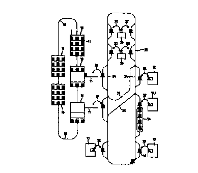
Dans le but de réaliser un grand nombre d'essais chimiques/biologiques identiques à une petite échelle, à l'aide d'un grand nombre de substances provenant de bibliothèques de substances, lesdites substances sont introduites dans les cavités de plaquettes d'essai et testées dans ces cavités, les plaquettes étant traitées dans différents postes de traitement (12, 12.1, 20). Les plaquettes sont stockées dans des récipients de stockage (10) sous forme de piles de plaquettes (1). Ces piles de plaquettes (1) sont chargées et déchargées à l'aide de moyens de manipulation de piles (31). Les piles de plaquettes sont ensuite chargées sur des moyens de transport (12) et transportées individuellement par ces derniers jusqu'aux postes de traitement (12, 12.1, 20) sur un système de rails (33/34/35). Les plaquettes sont séparées de la pile en vue de leur traitement une fois qu'elles ont atteint les postes de traitement (12, 12.1, 20), après quoi elles sont à nouveau placées dans une pile (1). Chaque poste de traitement (12, 12.1, 20) comprend au moins un élément de séparation de plaquette (32) destiné à réaliser cette fonction de séparation. Chaque pile de plaquettes (1) possède une pluralité de plaquettes empilées l'une sur l'autre et une plaque de recouvrement. Avantageusement, toutes les piles ont sensiblement la même taille.


Abrégé anglais


In order to conduct a large number of identical chemical/biological tests on a
microscale using a large number of substances from substance libraries, said
substances are inserted in the cavities of test plates and tested in the
cavities, whereby the plates are treated in different treatment stations (12,
12.1, 20). The plates are stored in storage containers (10) in the form of
plate stacks (1). Said plate stacks (1) are loaded and unloaded using stack
manipulation means (31). The plate stacks are then loaded on a means of
conveyance (12) and individually transported by said means of conveyance (12)
to the treatment stations (12, 12.1, 20) on a rail system (33/34/35). The
plates are separated from the stack for treatment once they have reached the
treatment stations (12, 12.1, 20), after which they are once again placed in a
plate stack (1). Each treatment station (12, 12.1, 20) comprises at least one
plate separation element (32) to carry out this separation function. Each
plate stack (1) has a plurality of plates stacked on top of each other and a
cover plate. Advantageously, all stacks are substantially the same size.

Revendications

Note : Les revendications sont présentées dans la langue officielle dans laquelle elles ont été soumises.


CLAIMS
1. Method for carrying out large numbers of similar chemical/biological tests,
in
which method large numbers of different compounds are inserted into
cavities (3) of plates (2) and are subjected to test reactions and
measurements,
wherein the plates (2) are transported in a succession of individually
transported plate stacks (1, 1.1, 1.2) along a predetermined treatment path
being substantially closed in itself to selected ones of a plurality of
treatment
stations (12, 12.1, 20) and away from the selected treatment stations (12,
12.1, 20),
wherein not selected treatment stations (12, 12.1, 20) are bypassed,
wherein in selected treatment stations, freely selectable plates (2) are
removed from plate stacks (1, 1.1, 1.2) for the application of compounds, for
test reactions or for measurements, are positioned in a treatment position
(13)
and are repositioned in plate stacks (1, 1.1, 1.2),
wherein plates (2) in plate stacks (1, 1.1, 1.2) are stored in movable storage
containers (10) in individually accessible plate stacks (1, 1.1, 1.2), which
containers can be brought into a manipulating position,
wherein plates (2) are manipulated in plate stacks (1, 1.1, 1.2) between
storage and transport and
wherein in each plate stack (1, 1.1, 1.2) a plurality of plates (2) are
loosely
superimposed and a covering plate (4) lies on the uppermost plate.

2. Method according to claim 1, wherein the different compounds are taken
from cavities (3) of library plates (2) and are transferred to cavities (3) of
plates (2) for which, in the same treatment station, plates (2) are removed
from two plate stacks (1.1, 1.2) and are replaced in two plate stacks (1.1,
1.2).
3. Method according to claim 1 or 2, wherein each plate (2) which is removed
from a plate stack (1, 1.1, 1.2) in a treatment station (12, 12.1, 20) is
repositioned in the same location in the same plate stack (1, 1.1, 1.2) after
treatment.
4. Method according to one of claims 1 to 3, wherein a specific storage
location
in a storage container (10) is allocated to each stack (1, 1.1, 1.2).
5. Method according to one of claims 1 to 4, wherein standardized microtest
plates are used as plates (2).
6. Method according to claims 1 to 5, wherein the plate stacks (1, 1.1, 1.2)
are
transported with the help of individually drivable transport means (12) along
a system of rails (33, 34, 35) and switch points from a storage area to the
treatment stations (12, 12.1, 20) and from a treatment station (12, 12.1, 20)
to
a next treatment station (12, 12.1, 20).
7. Method according to one of claims 1 to 6, wherein the plates (2) are
separated
for preheating and are incubated in a plate stack (1, 1.2) directly after the
preheating.

8. Method according to claim 7, wherein for incubation, the plate stacks (1,
1.2)
are transported through a continuous incubator (36).
9. Device for carrying out large numbers of identical chemical/biological
tests,
wherein large numbers of different compounds are inserted into cavities (3)
of plates (2) and are subjected to test reactions and measurements, which
device comprises a plurality of treatment stations (12, 12.1, 20) for
insertion
compounds into cavities (3) of plates (2) and for subjecting the compounds in
the cavities (3) of plates (2) to test reactions and measurements, storage
means for storing plates (2) in plate stacks (1, 1.1, 1.2), means for
transporting plates (2) in plate stacks (1, 1.1, 1.2) from storage to selected
treatment stations (12, 12.1, 20) and between selected treatment stations (12,
12.1, 20),
wherein the means for transporting comprises a rail system substantially
closed in itself and stack transporting means (15) individually movable on the
rail system (33, 34, 35) and the stack transporting means (15) are movable on
the rail system to and away from selected treatment stations (12, 12.1, 20)
and past non-selected treatment stations (12, 12.1, 20) on bypasses,
wherein there is at least one plate separation element (32) allocated to each
treatment station (12, 12.1, 20) for freely selectable removal of individual
plates (2) from a plate stack (1) transported to the treatment station (12,
12.1,
20), for positioning the removed plate (2) in a treatment position (13) of the
treatment station (12, 12.1, 20) and for repositioning individual plates (2)
in a
plate stack (1, 1.1, 1.2),
wherein the storage means for storing plate stacks (1, 1.1, 1.2) comprises
storage containers (10) being movable along a path, being positionable in at

least one manipulating position and allowing removal and repositioning of
individual plate stacks (1, 1.1, 1.2) in a freely selectable order,
wherein stack manipulating means (31) for removing stacks (1, 1.1, 1.2) from
storage, for re-storing stacks (1, 1.1, 1.2) and for loading and unloading
stack
transport means (15) are allocated to each manipulating position and
wherein the plates (2) are equipped for loosely superimposed stacking and a
covering plate (4) is provided for each stack (1, 1.1, 1.2).
10. Device according to claim 9, wherein for removal of compounds from
cavities (3) of library plates and for transferring the removed compounds to
cavities (3) of plates (2) at least one treatment station (20) with two plate
separation elements (32) is provided.
11. Device according to claims 9 or 10, wherein the storage containers (10)
comprise draw-out shelves (11) on which plate stacks (1, 1.1, 1.2) are
positionable distanced from each other.
12. Device according to claim 11, wherein a plurality of storage containers
(10) is
provided which are movably along a rail (30).
13. Device according to one of claims 9 to 12, wherein the rail system (33,
34,
35) comprises controlled switch points.
14. Device according to one of claims 11 to 13, wherein the stack manipulating
means (31) comprises a gripper being movable from above towards a drawn

out shelf (11), being equipped for gripping a plate stack (1, 1.1, 1.2) and
being movable above a transport means being positioned on the rail system
(33/34/35) and lowerable onto said transport means.
15. Device according to one of claims 9 to 14, wherein the plate separation
elements (32) comprise a stack shovel (40) for removing a stack (1, 1.1, 1.2)
from a transport means positioned in a transfer position (42), for moving the
stack into a working position (43) and for lifting the stack to different
levels
in the working position.
16. Device according to claim 15, wherein the plate separation element (32)
comprises an upper pair (50) and a lower pair (51) of supporting parts
cooperating with the stack shovel (40) in the working position (43), the
support parts being pivotable into a resting position and a holding position.
17. Device according to claim 16, wherein the plate separation elements (32)
comprise a plate sledge (41) being displaceable between the treatment
position (13) and the working position (43).
18. Device according to one of claims 9 to 17, wherein the at least one
treatment
station is a preheating station (12.1) and wherein this preheating station
(12.1)
is followed downstream by an incubator (36).
19. Device according to claim 18, wherein the incubator (36) is a continuous
incubator with at least one rail track leading through it.

20. Device according to one of claims 1 to 19, wherein the at least one
treatment
station comprises a plate transporting means leading from an entrance point
to an exit point and wherein a first separation element for positioning
individual plates in the entrance point is allocated to the entrance point and
a
second separation element for removing individual plates from the exit point
is allocated to the exit point.

Description

Note : Les descriptions sont présentées dans la langue officielle dans laquelle elles ont été soumises.


CA 02318548 2000-07-17
P 1321.PCTe 03.07.00
-1-
METHOD AND DEVICE FOR CARRYING OUT LARGE NUMBERS OF
SIMILAR BIOLOGICAL/CHEMICAL TESTS ON A MICROSCALE
The invention is in the field of automated microanalysis and relates to a
method
according to the generic part of the first independent claim. The method
serves for
carrying out large numbers of similar biological/chemical tests on a
microscale
(assays). For carrying out such assays, libraries of test compounds are used
and all or
selected ones of the compounds present in a compound library are submitted to
the
same test. The method can also be used for selecting compounds from a compound
library. The invention also relates to a device according to the generic part
of the
corresponding, independent claim, which device serves for carrying out the
method.
to Compound libraries, e.g. libraries of synthetic, organic molecules are
known in form
of large numbers of plates each having a plurality of cavities, wherein each
cavity
contains one of the compounds dissolved in a standard solvent and in an amount
sufficient for a large number of microtests. In the following, plates with
cavities
containing such large amounts of a compound are referred to as "library
plates". For
carrying out a series of tests, "test plates" are prepared using the compounds
of
library plates by removing test quantities of the compounds contained in the
cavities
of the library plates and by transferring them to empty cavities of further
plates. Test
plates containing one compound only in each cavity as well as test plates
containing
compound mixtures in each cavity can be prepared in substantially the same
manner.
Library plates as well as test plates are storable over longer periods of time
if contact
with air or oxygen respectively is prevented or at least largely reduced.
Assaying compounds of a compound library in the manner as shortly described
above serves e.g. for finding compounds having a specific pharmacological
effect.

CA 02318548 2000-07-17
P 1321.PCTe U3.07.00
-2-
For carrying out the tests, usually each test plate is treated in a plurality
of successive
treatment steps in a plurality of treatment locations. The treatment is e.g.
carried out
in three treatment steps: addition of one or several liquid reagents for
effecting a
reaction with the compound to be tested; incubation in a predetermined
atmosphere
and a predetermined temperature for a predetermined time; addition of further
liquid
reagents for stopping the reaction and/or for a color reaction; measurement of
a
specific property of the reaction mixture (color, fluorescence, radiation
etc.). A step
for reaction mixture separation and for removal of part of the reaction
mixture (e.g.
filtration or centrifugation) may also be provided.
1o For assays as described above, usually standardized plates with e.g. 96 (8
x 12)
cavities (microtest plates) are used, which plates comprise means for
stabilizing the
plates when stacked (e.g. a protruding rim on the upper side of the plate and
a
corresponding groove on the lower side of the plate). The treatment stations
necessary for charging the cavities of the plates and for carrying out the
assays as
well as the means for transporting the plates from one treatment station to
the next
are controlled by a central control unit. The treatment path from a first
treatment
station to a last treatment station, which each plate must cover for a
specific test to be
carried out may be different for different tests. Usually the plates are moved
behind
each other along the treatment path such that at any time there is a plurality
of plates
2o present along the treatment path.
Transport of the individual plates from a store to a first and then following
treatment
stations and possibly back to a store is usually carried out by means of a
suitably
controlled robot arm within the reach of which all treatment stations and
storage
containers are arranged. This robot arm by which all plates on the treatment
path are
transported, carries out a large number of different transport steps per time
unit,
whereby with each of these transport steps a plate is transported along a part
of the
treatment path, e.g. from one treatment station to the next. It is obvious
that the robot

- CA 02318548 2000-07-17
P 1321.PCTe 03.07.00
-3 -
arm must run through a succession of very complicated movements and that it
must
also carry out a large number of lost travels (movements without plate)
between the
actual transport steps. This robot arm proves to be the one part of a test
system
limiting the speed of assaying.
The number of compounds contained in one of the described compound libraries
needs to be very large and constantly growing if it is to be sufficient for
comprehensive tests. Compound libraries with several hundred thousand
compounds
are quite usual and are being enlarged further. Together with the libraries,
the
number of tests in a test series also grows. This means that for carrying such
large
to numbers of tests in a useful amount of time it is getting more and more
important to
have test systems enabling a throughput rate as large as possible. There is a
need for
means and ways with which the effciency of methods cannot only be gradually
increased but can be lifted to a different dimension.
For the above reason, the object of the invention is to create a method and a
device
allowing a considerably larger number of tests to be carried out than is
possible with
known methods and devices, and allowing this increase in efficiency without a
substantial increase regarding machinery (treatment stations). With the
inventive
method and the inventive device it is to be possible to achieve capacities in
the order
of 100,000 tests per day using known microtest plates with 96 cavities and
without
2o using parallel working treatment stations. The method and the device are,
however,
not to be limited to this specific sort of standardized plate, such that by
using plates
with more cavities a further capacity increase can be achieved. Furthermore,
it is to
be possible to carry out the method using known treatment stations.
The basic idea of the inventive method substantially consists in not handling
individual plates as done so far but handling stacks of plates, whereby all
handled

CA 02318548 2000-07-17
P1321.PC'Te 03.07.00
-4-
stacks of plates advantageously have the same size, i.e. all comprise the same
number of plates. According to the inventive method, all plates (test plates,
empty
plates and library plates) are stored in stacks, are manipulated in stacks and
are
transported in stacks. Only for treatment in treatment stations the plates are
separated
from stacks, are treated as individual plates and are inserted into stacks
again after
treatment. By such stack management, plate tragic on the treatment paths is
simplified and compared to known plate management throughput is considerably
increased.
A stack of plates e.g. comprises ten plates. In the stack, each plate covers
the one
1o underneath and on the top of the stack there is a covering plate covering
the
uppermost plate. This covering plate does not have any other function. As the
plates
in the stack cover each other during most of the time during assaying,
individual
covers for plates are not necessary. This is a further advantage of the
inventive
method.
For carrying out the inventive method, a plurality of treatment stations is
provided,
each treatment station being equipped with at least one means for separating
plates
from a stack, i.e. a means for taking one plate out of a stack, positioning
the plate in a
treatment position and for rearranging the plate in the stack after treatment.
Furthermore, a plurality of transport means is provided with each of which at
least
one stack of plates can be transported individually along a treatment path and
stack
manipulating means with which stacks of plates are removed from storage
containers
and loaded onto transport means and stacks of plates are unloaded from
transport
means and put back into storage. The inventive device, comprising treatment
stations
with plate separating means, stack transporting means, storage containers and
stack
manipulating means is controlled by a central computer, as is usual for
similar
installations with plate management, such that assaying can be carried out in
a fully
automated manner.

CA 02318548 2000-07-17
P 13 21.PCTe 03.07.00
-S-
It is advantageous for every specific plate to have a specific position in a
specific
stack to which position it is returned after every separation. It is also
advantageous
for each specific stack of plates to be used several times {library plates) to
have a
specific storage position in a storage container, to which position the stack
is always
s returned. In order for the test series to be able to be carried out without
loss of
freedom in relation to carrying out tests with plate management, the
separation
means are to be designed such that they can remove any plate from a stack and
place
it back in its position. Furthermore the storage containers and stack
manipulating
means are to be designed such that each stored stack can be taken out of or
put into
1o storage independently of which other stacks are present in the store.
The condition of the substantiaily unchanging plate position in the stack and
the
unchanging stack position in the store is, however, not compulsory to the
inventive
method. With the help of a correspondingly complicated management software it
is
also possible to localize plates and stacks in a constantly changing
"disorder" and to
15 extract them for treatment.
In any case, the storage containers are to be designed such that an arbitrary
access to
all stacks is possible, such that for loading plates with compounds and for
carrying
out tests, the selection of stacks from a storage container is completely free
and
totally independent of the storage order. This is not valid for individual
plates in the
2o storage area. If e.g. only one plate from a stack is to be treated the
whole stack is
removed and transported and only the plate to be treated is separated in the
treatment
stations. This means that for storage and removal an arbitrary access to any
individual stack must be guaranteed and for the separation of plates from
stacks an
arbitrary access to any individual plate must be guaranteed.

CA 02318548 2000-07-17
P1321.PCTe 03.07.00
-6-
For stack storage e.g. storage containers are used with draw-out shelves on
which the
stacks are positioned distanced from each other, such that, with the help of a
stack
manipulating means comprising a corresponding gripper each stack can be
removed
from a drawn out shelf from above and/or can be positioned on such a shelf in
an
unoccupied position. For transporting stacks e.g. individual transport means
are
provided which are movable on a rail system comprising controlled switch
points.
These transport means are loaded with at least one stack by the stack
manipulating
means and they transport the one stack along a test path being predetermined
for a
specific test series and leading the transport means to a predetermined
sequence of
treatment stations.
The inventive method and the inventive device are described in detail in
connection
with the following Figures, wherein:
Figure 1 shows an exemplified stack of plates as used in the inventive method;
Figure 2 is a diagrammatic representation of a test being carried out
according
to the inventive method;
Figure 3 is a diagrammatic representation of the preparation of test plates
from
library plates or of the preparation a further generation of library
plates from an earlier generation of library plates according to the
inventive method;
2o Figure 4 is a diagrammatic representation of an exemplified embodiment of
the
inventive device for carrying out the inventive method;
Figure 5 is a diagram of an exemplified embodiment of a plate separating
means;

P1321.PCTe
CA 02318548 2000-07-17
03.07.00
_ '7 _
Figure 6 shows a detail of the plate separating means.
Figure 1 shows a stack 1 of plates 2 with cavities 3 as used in the inventive
method.
On its top, the stack 1 carries a covering plate 4, which, as shown comprises
no
cavities or comprises empty cavities and the only function of which consists
in
covering the cavities of the second plate from the top. The covering function
for all
other plates of the stack is taken over by the next upper plate in the stack.
The plates 2 comprise stacking means matched to each other on their top and
bottom
sides, e.g. tongue-shaped rims 5 on the upper side and corresponding grooves
(not
shown) on the bottom side, such that stacks are relatively stable.
Advantageously, the
to surfaces 6 on which stacks are positioned, i.e. e.g. shelves of storage
containers,
supporting areas of transport means and treatment positions of treatment
stations are
equipped with the same stacking means, such that the stacks can be easily and
accurately positioned in defined positions. It is also possible for the
bottommost plate
of each stack to comprise different positioning means co-operating with
corresponding means of a supporting surface or that each stack comprises a
specific
bottommost positioning plate which, like the covering plate has no other
function.
Figure 2 shows, in a very diagrammatic representation, an example of a test
being
carried out according to the inventive method. In successive phases a to i the
stack or
plate movements to be carried out are shown by means of arrows, wherein
sequences
of phases are possibly repeated. The individual phases are:
a. in a storage container 10 having shelves 11, a stack 1 of test plates is
stored
together with other stacks of test plates. In order to test the test compounds
in
the cavities of the test plates of stack 1, the storage container 10 is opened
and the shelf 11 is drawn out;

CA 02318548 2000-07-17
P 1321.PCTe 03.07.00
_g_
b. stack 1 is gripped by stack manipulating means (not shown) and is lifted
off
shelf 11;
c. stack 1 is loaded onto a transporting means 12 and is transported to a
treatment station 12;
d. one plate of the stack 1 (e.g. the one directly underneath the covering
plate) is
positioned in the treatment position 13 of the treatment station 12 with the
help of a plate separation element (not shown) and is treated;
e. the plate is removed from the treatment station with the help of the plate
separation element (not shown) and is repositioned in stack l;
to if required, steps d and a are repeated for further plates in stack 1;
f. stack 1 is transported further;
if required, steps d, a and f are repeated in a next treatment station;
g. the stack is transported back to the storage container 10 and is
repositioned on
shelf 11 by means of the stack manipulating means (not shown);
h. shelf 11 is pushed back into the storage container 10;
i. storage container 10 is closed.
Figure 2 shows the treatment path of only one stack 1. When carrying out a
test
series however, a plurality of stacks are in motion in succession on the
treatment path
such that stacks are constantly removed and repositioned out of or in the
storage
2o container or even out of or in a plurality of storage containers and such
that in the
treatment stations plates from one stack after the other are treated, wherein
the

CA 02318548 2000-07-17
P 1321.PCTe 03.07.00
-9-
loaded transport means can also be buffered in front of treatment stations. A
transport means having been unloaded is loaded again with a stack from the
same or
from a different storage container.
Figure 3 shows, in the same diagrammatic manner as Figure 2, a treatment
involving
two plates or two stacks of plates at a time, e.g. preparation of library
plates (further
generation) on which plates a selection of compounds from a mother library is
deposited or preparation of test plates using library plates. Removal and
replacing of
the stacks of plates from and in storage containers is not shown. It is the
same as
described above in connection with Figure 2.
to Figure 3 shows with arrows the stack and plate movements to be carried out
in
successive phases k to p:
k. a stack 1.1 of library plates and a stack 1.2 of empty plates are each
transported to a treatment station 20 on a transport means 12, which treatment
station 20 is equipped for removal of liquid from cavities and for addition of
liquid to cavities (liquid handling station) and which treatment station 20 is
equipped with two plate separation elements (not shown).
1. a library plate is removed from stack 1.1 and is brought into a treatment
position and compounds are removed from at least one cavity;
m. the library plate is repositioned in stack 1. l;
2o n. an empty plate is removed from stack 1.2 and is brought into a treatment
position and the at least one compound removed form the library plate is
placed into a cavity, such making of the empty plate a test plate;

P 1321.PCTe
CA 02318548 2000-07-17
03.07.00
-10-
o. the test plate is repositioned in stack 1.2;
if necessary, steps 1 to o are repeated with further plates from stack 1.1
and/or from
stack 1.2;
p. the stacks are transported away, stack 1.1 e.g. to be returned to store and
stack 1.2 to be directly treated in the treatment stations along a treatment
path
or to be returned to storage also.
Figure 3 may create the impression that the movements of stacks 1.1 and 1.2
are
simultaneous. This is not at all a condition to the inventive method. For e.g.
preparation of library plates of a second generation containing only a
selection of the
compounds of the mother library, e.g. compounds from several mother library
plates
are transferred to only one empty plate and the stack movements to and from
the
treatment station are not at all simultaneous.
Figure 4 shows, in a very diagrammatic representation, an exemplified device
for
carrying out the inventive method, as was described in connection with Figures
1 to
3. The device comprises a storage area shown on the left and a treatment area
shown
on the right.
In the storage area, a plurality of storage containers 10 with draw-out
shelves is
provided, the storage containers e.g. being selectively movable into the area
of a
stack manipulating means along a rail 30 (broken line). The stack manipulating
2o means is shown as a double arrow connecting the storage area with the
treatment
area. Advantageously, more than one stack manipulating means 31 (e.g. two) is
provided, such that plates from several storage containers can be manipulated
at the

CA 02318548 2000-07-17
P 1321.PCTe 03.07.00
same time. In the area of the stack manipulating means 31, means for opening
storage containers 10 and for drawing out shelves 11 are also provided.
The treatment area comprises a plurality of treatment stations 12 with one
plate
separation element 32 and treatment stations 20 with two or more plate
separation
elements 32. The plate separation elements are shown as double arrows, which
connect the stack transportation system with treatment stations 12 or 20. The
stack
transportation system consists of a rail system 33 (broken lines) with
bifurcations in
which controlled switch points are provided. The rail system is advantageously
closed in itself and leads into the area of the stack manipulating means 31
and the
1o plate separation elements 32, wherein the rail system is advantageously
designed
with bypasses 43 for all these areas.
Stack transportation means 12 are individually movable along the rails of the
rail
system. The rail system may be used for transport in one direction only (e.g.
clockwise) whereby possible treatment paths differ in bypassing specific
treatment
stations. However, the rail system may comprise transverse connections 35 and
have
areas used in both directions such that e.g. treatment paths with different
treatment
sequences or a shortened return of stacks of library plates becomes possible.
Most of the tests to be carried out contain, as previously mentioned, a step
of
incubation in a predetermined atmosphere and at a given temperature. Using the
2o inventive method it is particularly advantageous to incubate the plates in
stacks.
However, stacks of plates have a relatively large mass and therefore, when the
stack
is brought into an environment of a nominal temperature, different positions
within
the stack reach this nominal temperature with largely different delays. For
this reason
it is suggested to preheat the stack before incubation. This is done by
preheating
separated plates in succession, e.g, by means of positioning plate after plate
on a

CA 02318548 2000-07-17
P 1321.PCTe 03.07.00
-12-
metal surface at the nominal temperature for a short time. The preheated
plates are
brought back into the stack, which is then transported into an incubator. The
incubator is advantageously a continuous incubator through which at least part
of the
rails of the transport system pass.
According to Figure 4, one of the treatment stations is equipped as a
preheating
station (12.1) and is followed downstream by a continuous incubator 36, which
is
passed through by a plurality of stacks on transport means at such a speed
that the
stacks reach the exit when their given incubation time is over.
In a dii~erent embodiment, a treatment station for preheating or incubation
may be
1o equipped with a plate separation element at its entrance and a plate
separation
element at its exit and with an internal plate transportation means for
transporting
individual plates from the entrance to the exit. In such a case, plates are
individually
supplied by the first separation element to the internal transport means, are
transported from the entrance to the exit whilst being preheated or incubated
and are
then individually taken over by the second separation element at the exit to
be
restacked.
Figure 5 shows a diagram of an exemplified embodiment of the plate separation
element, which in Figure 4 is shown diagrammatically with a double arrow
denominated 32 and which is used in the inventive device for bringing a stack
1 from
2o a transport device into a working position of a treatment station, for
removing a plate
2 from the stack 1, for positioning it in the treatment position 13 of the
treatment
station, for repositioning it in stack 1 after treatment and for loading stack
1 back
onto the transport device. The plate separation element is shown in three
different
functional phases denominated a, b, c.

CA 02318548 2000-07-17
P 1321.PCTe 03.07.00
-13-
The plate separation element comprises a stack shovel 40 and a stack sledge
41.
These are movable into the following positions by corresponding drive and
control
means:
a. The stack shovel 40 is brought underneath a stack 1 which is held ready on
a
transport means (not shown) in a transfer position 42. The stack shovel 40
moves the stack 1 from the transfer position 42 into a working position 43
(horizontal double arrow).
b. The stack shovel 40 is brought to a height such that the plate to be
removed
from the stack is at the same height as the stack sledge 41 (vertical double
to arrow).
c. The plate 2 to be removed is moved into the treatment position of the
treatment station with the help of plate sledge 41 (horizontal double arrow).
For removing plate 2 from the treatment position 13, for reintegrating the
plate in
stack 1 and for loading the stack onto the transport means the steps shown
above are
carried out in reverse direction.
Figure 6 shows means for bringing stack 1 being positioned on stack shovel 40
into
a configuration for removal or repositioning a plate 2' in cooperation with an
up and
down movement of the stack shovel in the working position. Figure 6 is a view
from
the left side of the working position 43 of stack shovel 40, as it is shown in
Figure S.
2o The means, which interact with stack 1 for removing a plate 2' comprise in
addition
to the stack shovel, an upper and a lower pair 50 and 51 of pivoting support
parts
which are triggered individually to be pivoted from a holding position into a
resting
position. when pivoted into the holding position the support parts of pair 50
or 51
respectively are positioned from opposing sides underneath plates 2 or 2'

CA 02318548 2000-07-17
P1321.PCTe 03.07.00
-14-
respectively having a corresponding height in stack 1 positioned on the stack
shovel
40.
The lower pair 51 of support parts is arranged on a height such that a plate
positioned
on it is grippable by the plate sledge (not shown).
Figure 6 shows two functional phases, denominated a and b, of the pairs 50 and
S l of
support parts. These are:
a. The stack shovel 40 lifts stack 1 to a height such that plate 2' is
positioned on
the level of the upper pair 50 of support parts. The upper pair 50 of support
parts is pivoted from the resting position into the holding position, while
the
lower pair S 1 of support parts remains in the resting position.
b. The stack shovel 40 is lowered slightly, such that a gap forms between the
plate on the upper pair SO and the lower part of the stack. Then the lower
pair
51 of support parts is pivoted into the supporting position, such that plate
2'
to be removed comes to lie on these support parts and the stack shovel is
lowered slightly again. The plate 2' to be withdrawn is now separated from
the adjacent plates in a manner that it is removable by the plate sledge (not
shown) from stack 1 and can be reintegrated into the stack after treatment.
Using the means shown diagrammatically in Figure 6 it is also possible to
create a
gap in a stack in order to deposit a plate in it, or it is possible to close a
gap in a stack
2o created by removing a plate.

CA 02318548 2000-07-17
P 1321.PC'Te 03.07.00
-15-
The stack shovels 40, plate sledges 41 and pairs 50 and 51 of support parts,
shown in
Figures 5 and 6, are driven with suitable drive and control means
corresponding to
their function. One skilled in the art can realize the necessary drive and
control
means without problems such that it is unnecessary to describe these in detail
in the
s present specification.

Dessin représentatif
Une figure unique qui représente un dessin illustrant l'invention.
États administratifs

2024-08-01 : Dans le cadre de la transition vers les Brevets de nouvelle génération (BNG), la base de données sur les brevets canadiens (BDBC) contient désormais un Historique d'événement plus détaillé, qui reproduit le Journal des événements de notre nouvelle solution interne.

Veuillez noter que les événements débutant par « Inactive : » se réfèrent à des événements qui ne sont plus utilisés dans notre nouvelle solution interne.

Pour une meilleure compréhension de l'état de la demande ou brevet qui figure sur cette page, la rubrique Mise en garde , et les descriptions de Brevet , Historique d'événement , Taxes périodiques et Historique des paiements devraient être consultées.

Historique d'événement

Description Date
Exigences relatives à la révocation de la nomination d'un agent - jugée conforme 2022-01-27
Exigences relatives à la nomination d'un agent - jugée conforme 2022-01-27
Inactive : CIB de MCD 2006-03-12
Demande non rétablie avant l'échéance 2004-01-13
Le délai pour l'annulation est expiré 2004-01-13
Réputée abandonnée - omission de répondre à un avis sur les taxes pour le maintien en état 2003-01-13
Inactive : Supprimer l'abandon 2002-02-26
Inactive : Lettre officielle 2002-02-26
Réputée abandonnée - omission de répondre à un avis sur les taxes pour le maintien en état 2002-01-14
Lettre envoyée 2001-12-28
Inactive : Transfert individuel 2001-11-26
Lettre envoyée 2000-12-12
Inactive : Transfert individuel 2000-10-27
Inactive : Page couverture publiée 2000-10-24
Inactive : CIB en 1re position 2000-10-22
Inactive : Lettre de courtoisie - Preuve 2000-10-17
Inactive : Notice - Entrée phase nat. - Pas de RE 2000-10-10
Demande reçue - PCT 2000-10-03
Demande publiée (accessible au public) 1999-07-22

Historique d'abandonnement

Date d'abandonnement Raison Date de rétablissement
2003-01-13
2002-01-14

Taxes périodiques

Le dernier paiement a été reçu le 2002-01-11

Avis : Si le paiement en totalité n'a pas été reçu au plus tard à la date indiquée, une taxe supplémentaire peut être imposée, soit une des taxes suivantes :

  • taxe de rétablissement ;
  • taxe pour paiement en souffrance ; ou
  • taxe additionnelle pour le renversement d'une péremption réputée.

Les taxes sur les brevets sont ajustées au 1er janvier de chaque année. Les montants ci-dessus sont les montants actuels s'ils sont reçus au plus tard le 31 décembre de l'année en cours.
Veuillez vous référer à la page web des taxes sur les brevets de l'OPIC pour voir tous les montants actuels des taxes.

Historique des taxes

Type de taxes Anniversaire Échéance Date payée
Taxe nationale de base - générale 2000-07-17
Enregistrement d'un document 2000-10-27
TM (demande, 2e anniv.) - générale 02 2001-01-15 2001-01-05
Enregistrement d'un document 2001-11-26
TM (demande, 3e anniv.) - générale 03 2002-01-14 2002-01-11
Titulaires au dossier

Les titulaires actuels et antérieures au dossier sont affichés en ordre alphabétique.

Titulaires actuels au dossier
EPR LABAUTOMATION AG
Titulaires antérieures au dossier
ERNST BURGISSER
Les propriétaires antérieurs qui ne figurent pas dans la liste des « Propriétaires au dossier » apparaîtront dans d'autres documents au dossier.
Documents

Pour visionner les fichiers sélectionnés, entrer le code reCAPTCHA :


Pour visualiser une image, cliquer sur un lien dans la colonne description du document. Pour télécharger l'image (les images), cliquer l'une ou plusieurs cases à cocher dans la première colonne et ensuite cliquer sur le bouton "Télécharger sélection en format PDF (archive Zip)" ou le bouton "Télécharger sélection (en un fichier PDF fusionné)".

Liste des documents de brevet publiés et non publiés sur la BDBC .

Si vous avez des difficultés à accéder au contenu, veuillez communiquer avec le Centre de services à la clientèle au 1-866-997-1936, ou envoyer un courriel au Centre de service à la clientèle de l'OPIC.


Description du
Document 
Date
(aaaa-mm-jj) 
Nombre de pages   Taille de l'image (Ko) 
Dessin représentatif 2000-10-23 1 7
Description 2000-07-16 15 608
Abrégé 2000-07-16 1 89
Revendications 2000-07-16 6 186
Dessins 2000-07-16 5 102
Rappel de taxe de maintien due 2000-10-04 1 110
Avis d'entree dans la phase nationale 2000-10-09 1 193
Courtoisie - Certificat d'enregistrement (document(s) connexe(s)) 2000-12-11 1 113
Courtoisie - Certificat d'enregistrement (document(s) connexe(s)) 2001-12-27 1 113
Courtoisie - Lettre d'abandon (taxe de maintien en état) 2003-02-09 1 176
Rappel - requête d'examen 2003-09-15 1 112
Correspondance 2000-10-09 1 15
PCT 2000-07-16 13 475
Taxes 2001-01-04 1 27
Taxes 2002-01-10 3 91