Note : Les descriptions sont présentées dans la langue officielle dans laquelle elles ont été soumises.
CA 02323242 2000-10-16
-1-
ENGINE LUBRICATING APPARATUS AND METHOD OF OPERATING AN
ENGINE HAVING SUCH AN APPARATUS
BACKGROUND OF THE INVENTION
The present invention relates generally to the field of lubricating systems
for
internal combustion engines, and, more particularly, to an apparatus and
method of
lubricating the engine of a locomotive.
The filtration and conditioning of the lubricating oil of an internal
combustion
engine are critical for maintaining the reliability of the engine. It is known
that
particulate matter will become entrained in the lubricating oil during the
operation of
an internal combustion engine. The particulate matter may be introduced as a
byproduct of the combustion process or by the wearing of metallic parts within
the
engine. It is also possible that solid debris may enter an engine during a
maintenance
operation. It is known to provide a filter in the lubricating oil flow path of
an internal
combustion engine in order to remove particulate matter. As the oil is pumped
through the oil filter, particles entrained within the oil will become trapped
on the
filter media. Oil passing through the filter is then returned to the engine
essentially
free of particulate matter exceeding a certain size. It is known that such
filters have a
finite life depending upon the quantity of particulates within the oil and the
relationship of the size of the particulates to the size of the passages
through the filter.
Once a filter becomes sufficiently clogged with particulate matter, the flow
of oil
through the filter will become impeded. If the pressure of the oil is
sufficiently high,
a clogged filter may fail mechanically thereby allowing unfiltered oil to
bypass the
filter media.
In the field of locomotive engines as well as in most commercial applications,
it is desirable to extend the interval between oil and oil filter changes in
order to
maximize the on-train availability of the locomotive. The frequency of
lubrication
system maintenance usually depends upon one of two factors: the depletion of
certain
beneficial additives within the oil and the maximum useful life of the oil
filter. It is
known that certain additives such as surfactants, detergents and buffers
within
CA 02323242 2000-10-16
-2-
lubricating oil become depleted as an engine is operated. It is possible to
add
additional quantities of such additives to extend the interval between oil
changes.
However, the useful life of the oil filter may then become the limiting factor
defining
the interval between lubrication system maintenance services.
BRIEF SUMMARY OF THE INVENTION
Thus, there is a particular need for an apparatus and method for extending the
interval between oil filter changes in an internal combustion engine. A
lubricating
apparatus for an engine is described herein that provides such an extended
service
interval, the lubricating apparatus comprising a sump for containing oil, the
sump
disposed proximate a bottom portion of an engine and operable to collect oil
flowing
out of the engine; a pump having an inlet in fluid communication with the sump
and
operable to pump the oil through the lubricating apparatus and the engine; a
filter in
fluid communication with the pump and having an outlet in fluid communication
with
the engine for providing filtered oil to the engine; and a trap for collecting
solids
precipitating out of the oil in the sump, the trap being in fluid
communication with a
low point in the sump. The trap may be formed as a housing disposed below the
sump and may contain a plurality of meshes having a variety of opening sizes.
In
operation, the trap functions to contain particulate matter settling out of
the
lubricating oil and to prevent such solid matter from reentering the flow path
of the
oil. A fluid communication path may be provided from the bottom of the housing
back to the sump, with an auxiliary oil pump maintaining a small flow of oil
down
through the meshes to ensure that the particulate matter remains entrained in
the trap.
The auxiliary oil pump may remain in operation during periods of engine
shutdown to
promote the settling of particulate matter into the trap.
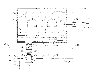
BRIEF DESCRIPTION OF THE DRAWING
The features and advantages of the present invention will become apparent
from the following detailed description of the invention when read with the
accompanying drawing which is a schematic illustration of a lubricating
apparatus for
an engine containing a trap for collecting solids.
CA 02323242 2000-10-16
-3-
DETAILED DESCRIPTION OF THE INVENTION
An engine 10 having a lubricating apparatus 12 is schematically illustrated in
the figure. The engine 10 may be any internal combustion engine, and in one
embodiment is the engine of a locomotive. The engine includes a block 14
containing
a plurality of moving parts 16 as is known in the art. A lubricant such as oil
18 is
utilized to minimize the friction on the moving parts 16 within the engine 10
and to
remove heat from selected parts such as bearings. The oil 18 may be
distributed
throughout the engine 10 in a variety of channels, such as the engine oil
header 20 as
may be provided in a diesel locomotive engine. A sump 22 for containing the
oil 18
is located at a bottom portion of the engine 10 and is operable to collect oil
flowing
out of the block 14. The sump 22 may be, for example, an oil pan attached to
the
bottom of an engine block 14. An oil pump 24 is utilized to pump the oil 18
throughout the engine 10. Pump 24 has an inlet line 26 that may draw oil
through a
strainer 28 located above the bottom of the sump 22. In order to avoid drawing
solid
objects into the inlet of the pump 24, it is known to locate the oil pump
suction inlet
above the bottom of the sump 22. In the embodiment illustrated in the figure,
a
strainer 28 is provided over the inlet to oil line 26. The outlet of pump 24
is directed
to a lube oil cooler 30, and then to a oil filter 32 before being directed
back to the
engine 10 through engine oil header 20.
The lubricating apparatus 12 further includes a trap 34 for collecting solids
precipitating out of the oil 18 in the sump 22. The trap 34 is in fluid
communication
with a low point 36 in the sump 22, which in the embodiment shown in the
figure is at
a point located remote from the oil pump suction inlet. In the embodiment
illustrated
in the figure, the trap 34 is a housing 34 having a plurality of meshes 38
contained
therein. The meshes 38 may be, for example, stainless steel screen material
having a
plurality of sizes, with the meshes 38 being vertically arranged within the
trap housing
34 so that the mesh sizes decrease from the top to the bottom. In this manner,
larger
particles will become entrapped on an upper mesh, while smaller particles
settle to
lower level meshes. Advantageously, trap 34 is in fluid communication with a
low
point in sump 22 wherein there is a relatively low flow velocity. As particles
CA 02323242 2000-10-16
-4-
precipitate from the oil into the trap housing 34, there is no upward flow of
the oil 18
causing them to be reintroduced into the oil in the sump 22. In this manner,
particles
of a variety of sizes are taken out of the flow of the lubricating oil 18,
thereby
reducing the amount of particles that must be entrained by filter 32. As a
result, filter
32 will have a longer usable life, thereby extending the interval between oil
filter
changes for engine 10. Trap 34 will also act as a passive recipient for
particles during
periods of shutdown of engine 10. When engine 10 is shut down and the oil
drains
into sump 22, the passive filtering action of trap 34 will continue as the
particles
entrained within the oil continue to settle out. Because there is no flow
through trap
34 during the operation of engine 10, even very small particles having settled
into trap
34 will remain within the trap and will not be drawn back into the primary oil
flow.
One or more of the meshes 38 may have a corrugated shape, such as mesh 39.
A corrugated mesh 39 will tend to collect particulate matter in the low points
of the
corrugations at a faster rate than at the high points of the corrugation. In
the event
that the mesh 39 becomes clogged at the low points of the corrugation, it will
still be
able to pass fluid and small particles through the unclogged high points of
the
corrugation, thereby increasing the interval before the mesh must be cleaned
or
replaced.
In the embodiment illustrated in the figure, the trap housing 34 is connected
to
the sump 22 by valve 40. Valve 40 may be any style of valve known in the art,
such
as a butterfly or ball valve for example. Valve 40 allows trap 34 to be
cleaned
without changing the oil 18 within the engine 10. Traps 34 may even be cleaned
during the operation of engine 10 if desired, assuming that proper safety
measures are
designed into such an embodiment to eliminate the risk of injury to the
personnel
performing such maintenance. In one embodiment, trap 34 is formed having a
cover
42 that may be removed to provide access to meshes 38. After engine 10 has
been
operated for a first period of time, the fluid communication between the trap
34 and
the sump 22 may be isolated by closing valve 40. Cover 42 may then be opened,
and
meshes 38 removed for cleaning and/or replacement. For the embodiment of a
stainless steel screen mesh 38, a majority of the entrapped particles may be
removed
by simply flushing the mesh 38 with a solvent such as kerosene. Once the
cleaned or
CA 02323242 2000-10-16
-$-
renewed meshes 38 are installed into the housing 34, the cover 42 may be
reinstalled
and the fluid communication between the trap 34 and the sump 22 reestablished
by
opening valve 40. The engine 10 may then be operated for an additional period
of
time prior to the replacement of oil 18 and filter 32.
$ In one embodiment, as illustrated in the figure, an auxiliary oil pump 44
may
be connected between an outlet 46 of the trap 34 and the sump 22 through an
isolation
valve 48. A drain line $0 having an isolation valve $2 may also be provided.
The
auxiliary oil pump 44 may be used to establish a small flow of oil into the
top of the
trap 34, thereby assuring that particles entering the trap and being entrained
on the
meshes 38 will not be washed back into sump 22. Auxiliary oil pump 44 may
remain
active even after the engine 10 is shut down and the main oil pump 24 is
deactivated.
By providing a small recirculating flow from the sump 22 through meshes 38,
the
precipitation of solid particles into the trap 34 may be maximized during the
engine
shutdown period. There may further be a recirculation line $4 connected
between trap
1$ 34 and oil pump 24 through valve $6 to provide a small flow through trap 34
during
the operation of oil pump 24. Valve $6 may provide fluid isolation and/or
throttling
of the rate of flow. Alternatively, the size of line $4 may be selected to
achieve the
desired low flow rate, and/or a flow restricting orifice $8 may be used.
Meshes 38 provide a convenient mechanism for the sampling of particles of a
variety of sizes from an operating engine. By isolating trap 34 from the sump
22 by
closing valves 40, 48, it is possible to remove a sample of particles from the
trap 34
for analysis purposes. With proper system design, such sampling may be done
without interfering with the normal operation of the engine 10.
By providing a debris trap at a low point within engine 10, the particles
drawn
2$ into trap 34 are likely to be of a different distribution of sizes than the
particles drawn
into oil pump 24 through oil line 26. For example, relatively larger particles
will
remain at the bottom of sump 22 and will not be drawn up into strainer 28.
Furthermore, relatively smaller particles that pass through filter 32 may be
collected
in the stagnant volume of the sump 34 assuming there is no flow through
auxiliary
pump 44. Alternatively, if auxiliary oil pump 44 is used, a much smaller mesh
size
may be used in the sump 34 than is used in the filter 32. The filtration size
of filter 32
CA 02323242 2000-10-16
-6-
is selected to accommodate a large flow volume, and to ensure that the filter
will not
become clogged with very small particles in a short time period, since the
consequences of the blockage of filter 32 are severe. However, engine 10 may
continue to operate safely without trap 34, so the minimum size of the meshes
38 may
be selected to be significantly smaller than the minimum mesh size of filter
32.
Therefore, sump 34 reduces the total quantity of particles that must be
captured by
filter 32, it may be entrain both larger and smaller particles than filter 32,
and it
provides a filtering action during periods of operation of engine 10 and
during periods
of engine shutdown.
Although trap 34 is illustrated as being a separate housing located below the
sump 22, additional embodiments may be envisioned having such a trap 34 formed
within a sump 22. A bulge or other low point formed in a sump or crankcase pan
may
preferably contain an opening for the insertion and removal of one or more
meshes.
In lieu of meshes, any structure forming a downwardly sloping tortuous path
for
particles precipitating out of the oil may be used. Such structure does not
inhibit the
precipitation of the particles into the trap, however it does inhibit the
circulation of oil
flowing above the trap from creating currents of flow into the trap, thereby
tending to
lift particles out of the trap. Preferably the flow of oil during the
operation of the
engine is across the inlet to the trap in a horizontal direction. Vertically
precipitating
particles are then removed from the horizontal flow path once they enter the
trap. The
walls of the trap limit the intrusion of the oil flow into the depths of the
trap. Thus
particles precipitating into the trap will not be drawn back into the main oil
flow
during subsequent periods of operation.
While the preferred embodiments of the present invention have been shown
and described herein, it will be obvious that such embodiments are provided by
way
of example only. Numerous variations, changes and substitutions will occur to
those
of skill in the art without departing from the invention herein. Accordingly,
it is
intended that the invention be limited only by the spirit and the scope of the
appended
claims.