Sélection de la langue

Search

Sommaire du brevet 2329971 

Énoncé de désistement de responsabilité concernant l'information provenant de tiers

Une partie des informations de ce site Web a été fournie par des sources externes. Le gouvernement du Canada n'assume aucune responsabilité concernant la précision, l'actualité ou la fiabilité des informations fournies par les sources externes. Les utilisateurs qui désirent employer cette information devraient consulter directement la source des informations. Le contenu fourni par les sources externes n'est pas assujetti aux exigences sur les langues officielles, la protection des renseignements personnels et l'accessibilité.

Disponibilité de l'Abrégé et des Revendications

L'apparition de différences dans le texte et l'image des Revendications et de l'Abrégé dépend du moment auquel le document est publié. Les textes des Revendications et de l'Abrégé sont affichés :

  • lorsque la demande peut être examinée par le public;
  • lorsque le brevet est émis (délivrance).
(12) Brevet: (11) CA 2329971
(54) Titre français: CADRE POUR MECANISME DE DIRECTION
(54) Titre anglais: STEERING GEAR FRAME
Statut: Périmé et au-delà du délai pour l’annulation
Données bibliographiques
(51) Classification internationale des brevets (CIB):
  • B62D 15/00 (2006.01)
  • B62D 03/12 (2006.01)
(72) Inventeurs :
  • LEE, UN-KOO (Republique de Corée)
(73) Titulaires :
  • HYUNDAI MOTOR COMPANY
(71) Demandeurs :
  • HYUNDAI MOTOR COMPANY (Republique de Corée)
(74) Agent: RICHES, MCKENZIE & HERBERT LLP
(74) Co-agent:
(45) Délivré: 2009-01-27
(22) Date de dépôt: 2000-12-29
(41) Mise à la disponibilité du public: 2002-02-24
Requête d'examen: 2005-10-25
Licence disponible: S.O.
Cédé au domaine public: S.O.
(25) Langue des documents déposés: Anglais

Traité de coopération en matière de brevets (PCT): Non

(30) Données de priorité de la demande:
Numéro de la demande Pays / territoire Date
2000-49152 (Republique de Corée) 2000-08-24

Abrégés

Abrégé français

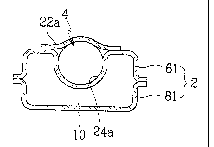
Un cadre pour mécanisme de direction comprenant des plaques supérieure et inférieure réunies au niveau de parties de bride pour définir un espace intérieur, un boîtier de direction disposé de façon à communiquer directement avec au moins une des plaques supérieure et inférieure, sans l'aide d'un support, et un élément de fixation pour fixer le boîtier de direction dans un état où le boîtier de direction est disposé pour communiquer directement avec au moins une des plaques supérieure et inférieure.


Abrégé anglais

A steering gear frame includes upper and lower plates joined together at flange portions to define an inner space, a steering gearbox disposed to directly contact at least one of the upper and lower plates without using a bracket, and a fixing member for fixing the steering gearbox in a state where the steering gearbox is disposed to directly contact at least one of the upper and lower plates.

Revendications

Note : Les revendications sont présentées dans la langue officielle dans laquelle elles ont été soumises.


WHAT IS CLAIMED IS:
1. A steering gear frame comprising:
upper and lower plates joined together at flange portions to define
an inner space;
a steering gearbox disposed to directly contact at least one of the
upper and lower plates in a bracket-less manner; and
a fastener for fixing the steering gearbox in a state where the
steering gearbox is disposed to directly contact at least one of the upper and
lower plates,
wherein the upper plate is provided with a concave portion indented
toward the inner space, the steering gearbox is tightly disposed in the
concave
portion, and the fastener for fixing comprises a fixing plate welded on the
upper
plate while covering the steering gearbox.
2. A steering gear frame comprising:
upper and lower plates joined together at flange portions to define
an inner space;
a steering gearbox disposed to directly contact at least one of the
upper and lower plates in a bracket-less manner; and
a fastener for fixing the steering gearbox in a state where the
steering gearbox is disposed to directly contact at least one of the upper and
lower plates,
wherein the lower plate is provided with a concave portion indented
toward the inner space, the steering gearbox is closely disposed in the
concave
8

portion, and the fastener for fixing comprises a fixing plate fixed on the
lower
plate while covering the steering gearbox.
3. A steering gear frame comprising:
upper and lower plates joined together at flange portions to define
an inner space;
a steering gearbox disposed to directly contact at least one of the
upper and lower plates in a bracket-less manner; and
a fastener for fixing the steering gearbox in a state where the
steering gearbox is disposed to directly contact at least one of the upper and
lower plates,
the steering gear frame further comprising a reinforcing plate fixed
on the lower plate while defining a predetermined space.
4. A steering gear frame comprising:
upper and lower plates joined together at flange portions to define
an inner space;
a steering gearbox disposed to directly contact at least one of the
upper and lower plates in a bracket-less manner; and
a fastener for fixing the steering gearbox in a state where the
steering gearbox is disposed to directly contact at least one of the upper and
lower plates,
wherein the upper plate is provided with a concave portion indented
toward the inner space, the steering gearbox is closely disposed in the
concave
9

portion, and the fastener for fixing comprises welding which fixes the
steering
gearbox on the upper plate.
5. The steering gear frame of claim 1 further comprising a reinforcing
plate fixed on the lower plate while defining a predetermined space.

Description

Note : Les descriptions sont présentées dans la langue officielle dans laquelle elles ont été soumises.


CA 02329971 2001-06-29
STEERING GEAR FRAME
BACKGROUND OF THE INVENTION
(a) Field of the Invention
The present invention relates to a steering gear frame, which is formed
by integrating a conventional suspension sub-frame and a steering gear box
with each other to support a steering gearbox assembly and a control links of
a
suspension system.
(b) Description of the Related Art
Generally, a conventional suspension sub-frame is a part of a front
wheel suspension system that is laterally arranged on a vehicle body to
connect
the suspension system to the vehicle body.
Accordingly, since the suspension sub-frame highly affects the rigidity
of the vehicle, it has to have rigidity higher than a predetermined level.
FIGS. 5 and 6 show a conventional suspension sub-frame and a
steering gearbox supported by the sub-frame.
As shown in the drawings, the conventional suspension sub-frame 100
comprises upper and lower plates 102 and 104 formed through a press process.
The upper and lower plates 102 and 104 are joined together at their flange
portions through a welding process, thereby defining a sealed tube having a
predetermined shape.
The upper plate 102 is elevated at its rear-middle portion to define an

CA 02329971 2001-06-29
elevated portion 106 on both sides of which mounting brackets 110 are formed.
The steering gearbox assembly 108 is fixed on the brackets 110 by fasteners
112.
In addition, the suspension sub-frame frame 100 is provided with
mounts 114 for mounting on the vehicle body.
When the suspension sub-frame 100 and the steering gearbox
assembly 108 are separately made and assembled together, the suspension
sub-frame 100 should be formed having a sufficient rigidity so that it works
well,
resulting in increasing its size and weight.
Furthermore, the elevated portion 106 for supporting the steering
gearbox assembly 108 causes an increase of weight and a reduction in space
in the engine compartment.
In addition, the assembly of the suspension sub-frame 100 and the
steering gearbox assembly 108 is time-consuming and increases the
manufacturing costs.
SUMMARY OF THE INVENTION
Therefore, the present invention is made in an effort to solve the above-
described problems.
It is an objective of the present invention to provide a steering gear
frame that is minimized in its size and increased in its rigidity, thereby
increasing the engine compartment space and reducing the weight of the
vehicle body.
2

CA 02329971 2001-06-29
It is another objective of the present invention to provide a steering gear
frame having a simple structure that can be easily assembled, thereby
shortening the assembling time and reducing the manufacturing costs.
To achieve the above objectives, the present invention provides a
steering gear frame comprising upper and lower plates joined together at
flange
portions to define an inner space; a steering gearbox disposed to directly
contact at least one of the upper and lower plates without using a bracket;
and
means for fixing the steering gearbox in a state where the steering gearbox is
disposed to directly contact at least one of the upper and lower plates.
According to a first embodiment of the present invention, the upper
plate is provided with a concave portion indented toward the inner space, the
steering gearbox is closely disposed in the concave portion, and the means for
fixing comprises a fixing plate welded on the upper plate while covering the
steering gearbox.
According to a second embodiment of the present invention, the lower
plate is provided with a concave portion indented toward the inner space, the
steering gearbox is closely disposed in the concave portion, and the means for
fixing comprises a fixing plate fixed on the lower plate while covering the
steering gearbox.
According to a third embodiment of the present invention, the steering
gearbox is fixed in the inner space defined between the upper and lower
plates.
The steering gear frame may further comprise a reinforcing plate fixed on the
lower plate while defining a predetermined space.
According to a fourth embodiment of the present invention, the upper
3

CA 02329971 2008-01-10
plate is provided with a concave portion indented toward the inner space, the
steering gearbox is closely disposed in the concave portion, and the means for
fixing comprises welding which fixes the steering gearbox on the upper plate.
In one aspect, the present invention resides in a steering gear frame
comprising: upper and lower plates joined together at flange portions to
define an
inner space; a steering gearbox disposed to directly contact at least one of
the
upper and lower plates in a bracket-less manner; and a fastener for fixing the
steering gearbox in a state where the steering gearbox is disposed to directly
contact at least one of the upper and lower plates, wherein the upper plate is
provided with a concave portion indented toward the inner space, the steering
gearbox is tightly disposed in the concave portion, and the fastener for
fixing
comprises a fixing plate welded on the upper plate while covering the steering
gearbox.
In another aspect, the present invention resides in a steering gear frame
comprising: upper and lower plates joined together at flange portions to
define an
inner space; a steering gearbox disposed to directly contact at least one of
the
upper and lower plates in a bracket-less manner; and a fastener for fixing the
steering gearbox in a state where the steering gearbox is disposed to directly
contact at least one of the upper and lower plates, wherein the lower plate is
provided with a concave portion indented toward the inner space, the steering
gearbox is closely disposed in the concave portion, and the fastener for
fixing
comprises a fixing plate fixed on the lower plate while covering the steering
gearbox.
In yet another aspect, the present invention resides in a steering gear
4

CA 02329971 2008-01-10
frame comprising: upper and lower plates joined together at flange portions to
define an inner space; a steering gearbox disposed to directly contact at
least one
of the upper and lower plates in a bracket-less manner; and a fastener for
fixing
the steering gearbox in a state where the steering gearbox is disposed to
directly
contact at least one of the upper and lower plates, the steering gear frame
further
comprising a reinforcing plate fixed on the lower plate while defining a
predetermined space.
In a further aspect, the present invention resides in a steering gear frame
comprising: upper and lower plates joined together at flange portions to
define an
inner space; a steering gearbox disposed to directly contact at least one of
the
upper and lower plates in a bracket-less manner; and a fastener for fixing the
steering gearbox in a state where the steering gearbox is disposed to directly
contact at least one of the upper and lower plates, wherein the upper plate is
provided with a concave portion indented toward the inner space, the steering
gearbox is closely disposed in the concave portion, and the fastener for
fixing
comprises welding which fixes the steering gearbox on the upper plate.
BRIEF DESCRIPTION OF THE DRAWINGS
The accompanying drawings, which are incorporated in and constitute a
part of the specification, illustrate an embodiment of the invention, and,
together
with the description, serve to explain the principles of the invention:
FIG. 1 is a sectional view of a steering gear frame according to a first
embodiment of the present invention;
FIG. 2 is a sectional view of a steering gear frame according to a second
4a

CA 02329971 2008-01-10
embodiment of the present invention.
FIG. 3 is a sectional view of a steering gear frame according to a third
embodiment of the present invention;
FIG. 4 is a sectional view of a steering gear frame according to a fourth
embodiment of the present invention;
FIG. 5 is a perspective view of a conventional suspension sub-frame and a
steering gearbox assembly; and
FIG. 6 is a sectional view of FIG. 5.
DETAILED DESCRIPTION OF THE PREFERRED EMBODIMENTS
Preferred embodiments of the present invention will be described
hereinafter with reference to the accompanying drawings.
FIG. 1 shows a steering gear frame according to a first embodiment of
4b

CA 02329971 2001-06-29
the present invention.
The inventive steering gear frame 2 comprises upper and lower plates
61 and 81, which are press-processed in a predetermined shape according to a
design specification.
~ The upper and lower plates 61 and 81 are joined together at their flange
portions by welding, defining a sealed tube having a space 10.
The steering gear frame 2 is provided with mounts (not shown) for
mounting to a vehicle body. The steering gear frame 2 is further provided with
suspension mounts on which control arms of a suspension system are mounted.
As a feature of the present invention, the steering gear frame 2 is
integrally formed with a steering gearbox assembly 4. That is, a concave
portion 24a indented toward the space 10 is formed on the upper plate 61, and
the steering gearbox assembly 4 is closely inserted into the concave portion
24a, and a fixing member 22a is welded on the upper plate 61 to fix the
steering
gearbox assembly 4, thereby integrating the steering gearbox assembly 4 with
the upper plate 61.
The concave portion 24a is designed having a size capable of receiving
a power cylinder (not shown) of the steering gearbox assembly 4. In addition,
the concave portion 24a and the fixing member 22a may function as the power
cylinder. That is, a rack gear can be directly disposed in a space defined by
the concave portion 24a and the fixing member 22a without the power cylinder.
When fixing the steering gearbox assembly 4 using the fixing member
22a, either a bolt coupling manner or a welding manner can be employed, but
the latter is more preferable in terms of rigidity.
5

CA 02329971 2001-06-29
As described above, since the steering gearbox assembly 4 is integrally
mounted on the upper surface of the upper plate 61 of the steering gear frame
2,
the whole size of the frame 2 can be minimized as there is no necessity for
the
elevated portion and the mounting brackets of the prior art.
Since the size of the steering gear frame 2 is reduced, it becomes easy
to obtain a space for it in the engine compartment. In addition, since the
number
of components can be reduced, the manufacturing costs can be lowered.
Furthermore, since the steering gearbox assembly 4 is integrated with
the steering gear frame 2, it functions as a structure of the steering gear
frame 2
to increase the rigidity.
FIG. 2 shows a steering gear frame according to a second embodiment
of the present invention.
In this embodiment, a bottom-middle portion of the lower plate 82 of the
steering gear frame 2 is indented inward to define a concave portion 24b in
which the steering gearbox assembly 4 is disposed. A fixing member 22b is
fixed on the bottom of the lower plate 82 while tightly integrating the
steering
gearbox assembly 4 with the lower plate 82 joined with the upper plate 62
FIG. 3 shows a steering gear frame according to a third embodiment of
the present invention.
In this embodiment, the steering gearbox assembly 4 is disposed within
the sealed tube defined by upper and lower plates 63 and 83 of the steering
gear frame 2.
That is, the steering gearbox assembly 4 is integrally disposed between
upper and lower plates 63 and 83 whose flanges are welded to each other.
6

CA 02329971 2001-06-29
In this embodiment, the steering gearbox assembly 4 further comprises
preferably a reinforcing plate 7 for enhancing the rigidity of the frame,
which is
welded on the lower plate 83, while defining a space.
FIG. 4 shows a steering gear frame according to a fourth embodiment
of the present invention.
This embodiment is identical to the first embodiment except for the
fixing member 22a.
That is, as shown in the drawing, an upper plate 64 of the steering gear
frame 2 is indented inward, and the steering gearbox assembly 4 is disposed
and welded on the upper plate 64 joined with a lower plate 84.
While this invention has been described in connection with what is
presently considered to be the most practical and preferred embodiment, it is
to
be understood that the invention is not limited to the disclosed embodiments,
but, on the contrary, is intended to cover various modifications and
equivalent
arrangements included within the spirit and scope of the appended claims.
7

Dessin représentatif
Une figure unique qui représente un dessin illustrant l'invention.
États administratifs

2024-08-01 : Dans le cadre de la transition vers les Brevets de nouvelle génération (BNG), la base de données sur les brevets canadiens (BDBC) contient désormais un Historique d'événement plus détaillé, qui reproduit le Journal des événements de notre nouvelle solution interne.

Veuillez noter que les événements débutant par « Inactive : » se réfèrent à des événements qui ne sont plus utilisés dans notre nouvelle solution interne.

Pour une meilleure compréhension de l'état de la demande ou brevet qui figure sur cette page, la rubrique Mise en garde , et les descriptions de Brevet , Historique d'événement , Taxes périodiques et Historique des paiements devraient être consultées.

Historique d'événement

Description Date
Le délai pour l'annulation est expiré 2015-12-29
Lettre envoyée 2014-12-29
Accordé par délivrance 2009-01-27
Inactive : Page couverture publiée 2009-01-26
Inactive : Taxe finale reçue 2008-10-01
Préoctroi 2008-10-01
Un avis d'acceptation est envoyé 2008-09-03
Lettre envoyée 2008-09-03
Un avis d'acceptation est envoyé 2008-09-03
Inactive : Approuvée aux fins d'acceptation (AFA) 2008-08-07
Modification reçue - modification volontaire 2008-01-10
Inactive : Dem. de l'examinateur par.30(2) Règles 2007-07-26
Inactive : CIB de MCD 2006-03-12
Lettre envoyée 2005-11-03
Exigences pour une requête d'examen - jugée conforme 2005-10-25
Toutes les exigences pour l'examen - jugée conforme 2005-10-25
Requête d'examen reçue 2005-10-25
Inactive : Page couverture publiée 2002-02-24
Demande publiée (accessible au public) 2002-02-24
Lettre envoyée 2002-02-08
Inactive : Lettre officielle 2001-09-17
Inactive : Correspondance - Transfert 2001-08-03
Modification reçue - modification volontaire 2001-06-29
Inactive : CIB en 1re position 2001-03-30
Inactive : Certificat de dépôt - Sans RE (Anglais) 2001-02-08
Lettre envoyée 2001-02-08
Demande reçue - nationale ordinaire 2001-02-05

Historique d'abandonnement

Il n'y a pas d'historique d'abandonnement

Taxes périodiques

Le dernier paiement a été reçu le 2008-11-05

Avis : Si le paiement en totalité n'a pas été reçu au plus tard à la date indiquée, une taxe supplémentaire peut être imposée, soit une des taxes suivantes :

  • taxe de rétablissement ;
  • taxe pour paiement en souffrance ; ou
  • taxe additionnelle pour le renversement d'une péremption réputée.

Les taxes sur les brevets sont ajustées au 1er janvier de chaque année. Les montants ci-dessus sont les montants actuels s'ils sont reçus au plus tard le 31 décembre de l'année en cours.
Veuillez vous référer à la page web des taxes sur les brevets de l'OPIC pour voir tous les montants actuels des taxes.

Titulaires au dossier

Les titulaires actuels et antérieures au dossier sont affichés en ordre alphabétique.

Titulaires actuels au dossier
HYUNDAI MOTOR COMPANY
Titulaires antérieures au dossier
UN-KOO LEE
Les propriétaires antérieurs qui ne figurent pas dans la liste des « Propriétaires au dossier » apparaîtront dans d'autres documents au dossier.
Documents

Pour visionner les fichiers sélectionnés, entrer le code reCAPTCHA :


Pour visualiser une image, cliquer sur un lien dans la colonne description du document. Pour télécharger l'image (les images), cliquer l'une ou plusieurs cases à cocher dans la première colonne et ensuite cliquer sur le bouton "Télécharger sélection en format PDF (archive Zip)" ou le bouton "Télécharger sélection (en un fichier PDF fusionné)".

Liste des documents de brevet publiés et non publiés sur la BDBC .

Si vous avez des difficultés à accéder au contenu, veuillez communiquer avec le Centre de services à la clientèle au 1-866-997-1936, ou envoyer un courriel au Centre de service à la clientèle de l'OPIC.


Description du
Document 
Date
(aaaa-mm-jj) 
Nombre de pages   Taille de l'image (Ko) 
Dessin représentatif 2002-01-29 1 6
Abrégé 2000-12-28 1 13
Description 2000-12-28 7 238
Revendications 2000-12-28 2 42
Dessins 2000-12-28 4 37
Abrégé 2001-06-28 1 17
Dessins 2001-06-28 4 51
Revendications 2001-06-28 2 52
Description 2001-06-28 7 277
Revendications 2008-01-09 3 66
Description 2008-01-09 9 333
Dessin représentatif 2009-01-12 1 7
Certificat de dépôt (anglais) 2001-02-07 1 162
Courtoisie - Certificat d'enregistrement (document(s) connexe(s)) 2001-02-07 1 136
Rappel de taxe de maintien due 2002-09-02 1 109
Rappel - requête d'examen 2005-08-29 1 116
Accusé de réception de la requête d'examen 2005-11-02 1 176
Avis du commissaire - Demande jugée acceptable 2008-09-02 1 163
Avis concernant la taxe de maintien 2015-02-08 1 170
Correspondance 2001-09-16 1 11
Taxes 2003-12-15 1 39
Taxes 2002-11-05 1 34
Taxes 2004-12-02 1 33
Taxes 2005-12-07 1 33
Taxes 2006-12-17 1 42
Taxes 2007-12-12 1 49
Correspondance 2008-09-30 1 52
Taxes 2008-11-04 1 51