Sélection de la langue

Search

Sommaire du brevet 2332792 

Énoncé de désistement de responsabilité concernant l'information provenant de tiers

Une partie des informations de ce site Web a été fournie par des sources externes. Le gouvernement du Canada n'assume aucune responsabilité concernant la précision, l'actualité ou la fiabilité des informations fournies par les sources externes. Les utilisateurs qui désirent employer cette information devraient consulter directement la source des informations. Le contenu fourni par les sources externes n'est pas assujetti aux exigences sur les langues officielles, la protection des renseignements personnels et l'accessibilité.

Disponibilité de l'Abrégé et des Revendications

L'apparition de différences dans le texte et l'image des Revendications et de l'Abrégé dépend du moment auquel le document est publié. Les textes des Revendications et de l'Abrégé sont affichés :

  • lorsque la demande peut être examinée par le public;
  • lorsque le brevet est émis (délivrance).
(12) Demande de brevet: (11) CA 2332792
(54) Titre français: DISPOSITIF DE MANIPULATION PENDANT LE PROCESSUS DE FABRICATION DES BROSSES A DENTS
(54) Titre anglais: TOOTHBRUSH MANUFACTURING HANDLING DEVICE
Statut: Réputée abandonnée et au-delà du délai pour le rétablissement - en attente de la réponse à l’avis de communication rejetée
Données bibliographiques
(51) Classification internationale des brevets (CIB):
  • A46D 03/08 (2006.01)
(72) Inventeurs :
  • SORRENTINO, ALAN V. (Etats-Unis d'Amérique)
(73) Titulaires :
  • COLGATE-PALMOLIVE COMPANY
(71) Demandeurs :
  • COLGATE-PALMOLIVE COMPANY (Etats-Unis d'Amérique)
(74) Agent: SMART & BIGGAR LP
(74) Co-agent:
(45) Délivré:
(86) Date de dépôt PCT: 1999-05-18
(87) Mise à la disponibilité du public: 1999-11-25
Licence disponible: S.O.
Cédé au domaine public: S.O.
(25) Langue des documents déposés: Anglais

Traité de coopération en matière de brevets (PCT): Oui
(86) Numéro de la demande PCT: PCT/US1999/010898
(87) Numéro de publication internationale PCT: US1999010898
(85) Entrée nationale: 2000-11-20

(30) Données de priorité de la demande:
Numéro de la demande Pays / territoire Date
09/083,014 (Etats-Unis d'Amérique) 1998-05-21

Abrégés

Abrégé français

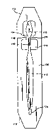
L'invention concerne un dispositif de manipulation pour la fabrication des brosses à dents, qui permet de manipuler les brosses à dents durant le processus de fabrication. Ce dispositif est un porte-brosse à dents rigide, dont les dimensions sont fixes et qui est facilement transportable sur un appareil du type transporteur. D'une manière générale, il prend la forme de la brosse à dents et se termine au moins par une cavité qui permet d'accueillir au moins la tête de la brosse à dents, de sorte que les soies ne touchent aucune surface interne de la cavité. S'il existe une seule cavité, celle-ci est suffisamment vaste pour permettre à un mécanisme de préhension d'attraper une partie de la brosse à dents, rendant possible l'insertion de la brosse dans le dispositif ou son extraction hors du dispositif. S'il existe plusieurs cavités, celles-ci sont séparées par une paroi support. Le dispositif améliore et facilite la manipulation des brosses à dents au cours des processus de fabrication et de traitement, et il protège les soies contre tout dégât pouvant survenir durant ces processus.


Abrégé anglais


A toothbrush handling device for handling of toothbrushes during the
manufacturing process. The device is a rigid toothbrush holder with fixed
dimensions which is easily transported in a conveyor type apparatus. The
holder is formed with a generally toothbrush-shaped portion and terminates in
at least one cavity suitable to hold at least the head portion of the
toothbrush such that the bristles do not contact any interior surface of the
cavity. If only one cavity is present, it is large enough to permit a gripping
mechanism to grasp a portion of the brush to permit the insertion of the brush
into or the removal of the brush from the transport device. Also, if more than
one cavity is present, the cavities are separated by a supporting wall. The
device enables improved and easier handling of the toothbrushes during
manufacturing and processing, and protects the bristles from damage during
those processes.

Revendications

Note : Les revendications sont présentées dans la langue officielle dans laquelle elles ont été soumises.


CLAIMS
Having described the invention as above, I claim:
1. A device for facilitating the transport of a toothbrush during a
manufacturing
process, said toothbrush having a head portion, a neck portion extending from
said
head portion and a handle portion extending from said handle portion, said
toothbrush having a plurality of bristles affixed to one surface of said head
portion,
said transport device comprising a solid body being formed with at least one
recess, said recess having a generally toothbrush-shaped portion and
terminating in
at least one cavity suitable to hold at least the head portion of said
toothbrush such
that the bristles do not contact any interior surface of said cavity, wherein
if only
one cavity is present, said cavity is of sufficient size to permit a gripping
mechanism to grasp a portion of said toothbrush to permit the insertion of
said
toothbrush into or the removal of said toothbrush from said transport device,
and
wherein if more than one cavity is present, said cavities are separated by a
supporting wall.
2. A transport device as claimed in claim 1, wherein said solid body includes
a second
cavity, said second cavity being of sufficient size to permit a gripping
mechanism
to grasp a portion of said toothbrush to permit the insertion of said
toothbrush into
or the removal of said toothbrush from said transport device, and wherein said
first
cavity holds at least the head portion of said toothbrush such that the
bristles do
not contact any interior surface of said first cavity.
7

3. A transport device as claimed in claim 2, wherein said solid body includes
a third
cavity, said third cavity being of sufficient size to permit a gripping
mechanism to
grasp a portion of said toothbrush to permit the insertion of said toothbrush
into or
the removal of said toothbrush from said transport device.
4. A device as claimed in claim 3, wherein the solid body is a regular
geometric
shape.
5. A device as claimed in claim 4, wherein the regular geometric shape is a
rectangle
or square.
6. A device as claimed in claim 4, wherein the regular geometric shape is a
polygon.
7. A device as claimed in claim 4, wherein the regular geometric shape is a
rectangle
with rounded corners.
8. A device as claimed in claim 4, wherein the regular geometric shape is a
rectangle
with angled corners.
9. A transport unit for use in automated brush processing, comprising, in
combination, a brush having bristles, a head, neck, and handle, with a
transport
body having a solid body, and two walled cavities separated by a support wall,
wherein
a) the bristles are within the first cavity and are not in contact with any
wall of
the cavity,
b) the neck of the brush rests on the support wall of the solid body,
8

c) the second cavity is below at least one part of the brush other than the
bristles, and
d) the handle of the brush rests on the transport body, whereby a stable unit
is
formed for transport in the automated processing.
10. A transport unit as claimed in claim 9, wherein the transport body is
formed with a
third cavity which engages the handle of the brush.
11. A transport unit as claimed in claim 10, wherein the third cavity
frictionally
engages the handle of the brush.
12. A transport unit as claimed in claim 9, wherein the transport body is
substantially
rectangular shaped with tapered corners.
13. The transport unit of claim 9 wherein said recess is of such depth that
said
toothbrush is wholly contained therewithin.
14. The transport unit of claim 9 wherein said toothbrush containing transport
bodies
are transported between processing operations in stacked groups.
15. The transport unit of claim 9 wherein said recess is of such depth that
said
toothbrush is partially contained therewithin.
16. The transport unit of claim 9 wherein said toothbrush containing transport
bodies
are transported between processing operations in aligned groups.
9

17. A method for processing a toothbrush having a head portion to which a
plurality
of bristle tufts is attached in an automated processing facility, comprising
the steps
of
a) providing at least one processing station;
b) providing a plurality of transport bodies, which transport bodies are
associated with at least one brush, and. which transport bodies include
generally brush-shaped recesses having at least one cavity therein;
c) engaging said plurality of transport bodies with said at least one brush
such
that the bristle portion of said brush head is contained within said at least
one cavity such that the bristles do not contact any interior surface of said
cavity, wherein if only one cavity is present, said cavity is of sufficient
size
to permit a gripping mechanism to grasp a portion of said toothbrush to
permit the insertion of said toothbrush into or the removal of said
toothbrush from said transport device, and wherein if more than one cavity
is present, said cavities are separated by a supporting wall;
d) transporting the combined brush and transport body to the at least one
processing station, and
e) conducting the at least one processing operation on the brush.
18. The method of claim 17 wherein said recess is of such depth that said
toothbrush is
wholly contained therewithin
19. The method of claim 17 wherein said toothbrush containing transport bodies
are
transported between processing operations in stacked groups.
20. The method of claim 17 wherein said recess is of such depth that said
toothbrush is
partially contained therewithin.
10

21. The method of claim 17 wherein said toothbrush containing transport bodies
are
transported between processing operations in aligned groups.
11

Description

Note : Les descriptions sont présentées dans la langue officielle dans laquelle elles ont été soumises.


~n
CA 02332792 2000-11-20
WO 99/59445 PCT/US99/10898
TOOTHBRUSH MANUFACTURING HANDLING DEVICE
BACKGROUND OF THE INVENTION
This invention relates to the field of brush .manufacture; specifically, to
the
manufacture of toothbrushes in an automated assemblyhprocessing facility.
Toothbrushes
must be handled carefully during processing and manufacture for several
reasons. First,
the bristles are especially delicate. Also, it is desired to result in a final
product which is as
flawless as possible, since a flawless surface results in a brush which is
more attractive and
of a higher value.
DESCRIPTION OF THE PRIOR ART
The related arts have recognized the usefulness of a carrier in an automated
assembly Line. US Patent 3,090,478 describes a container carrier adaptable for
receiving
containers or bottles of various sizes. This is said to avoid the necessity of
retooling a
production line for different sizes. US Patent 4,552,26() discloses a series
of pallets on a
guide extending past workstations.
US Patent 4,040,533 discloses multiple test sample transport means which holds
a
plurality of test tube type sample holders in a rectangular shaped containers.
US Patents 3,650,373 and 3,811,548 disclose v~ark holders on conveyors, while
US 4,305,496 discloses a method of transporting parts by dropping them into
containers
or "pucks" on a centrifugal feeder.
US Patent 4,694,950 discloses an open bottomed tray for supporting articles
while
they are being worked on from below.
US Patent x,736,830 discloses transport plates for a low-noise low-shock
operation. The plates may be polygonal, and have elements which fit within
positioning
recesses to lock them into position. US 4,739,607 discloses a pallet feeding
conveyor
1

n;
CA 02332792 2000-11-20
WO 99/59445 PCT/US99/10898
which places a pallet under a piece to be worked upon, then removes it and
returns it to
the beginning of a conveyor for use under another piece to be worked.
SUMMARY OF THE INVENTION
A novel rigid toothbrush holder with uniform dimensions that can be
transported
on a conveyor system has been developed by the inventor disclosed herein. The
holder is
formed with precise geometric dimensions so that it may be stacked, aligned,
and grouped
in lines for easy feeding, loading, stacking, or processing steps.
The invention is best understood by reference to the drawings.
BRIEF DESCRIPTION OF THE L>RAWINGS
Figure 1 A is a top plan view of a first embodiment of a transport device
according
to the present invention.
Figure 1B is a view in side elevation of a first variation of a transport
device
according to Figure 1 A.
Figure 1 C is a view in side elevation of a second variation of a transport
device
according to Figure 1 A.
Figure 2A is a top plan view of a second err~bodiment of a transport device
according to the present invention.
Figure 2B is a view in side elevation of a first variation of the transport
device
according to Figure ZA.
Figure ZC is a view in side elevation of a second variation of the transport
device
according to Figure 2A.
Figure 3A is a top plan view of a third embodiment of a transport device
according
to the present.
2

CA 02332792 2000-11-20
WO 99/59445 PCT/US99/10898
Figure 3B is a view in side elevation of a first variation of the transport
device
according to Figure 3 A.
Figure 3C is a view in side elevation of a second variation of the transport
device
according to Figure 3A.
Figure 4A is a top plan view of the inventive transport devices in line for
further
processing.
Figure 5 is a top plan view of the inventive transport devices stacked for
further
processing.
Figure 6 represents a schematic diagram of a toothbrush assembly line in which
the
transport device of instant invention is useful.
DETAILED DESCRIPTION
The device is formed of a solid body material such as high impact plastic,
aluminum, steel, or any other durable substance whi<;h will withstand the
rigors of
industrial handling.
The body 110 as shown in Figure 1 is generally rectangular, and a preferred
embodiment contains rounded or tapered ends 112 and 112' which enable easier
alignment and feeding in chutes, conveyors, and by spindles. Elongated
toothbrush 113,
having a head portion l 15, bristles 111 affixed to one surface of said head
portion, neck
portion I 17, and handle portion 123 is shown in Fig. 1B in outline and
resting partly in a
generally brush-shaped recess I24 within body 110. In. Fig. I C, handle
portion I23 is
shown in outline and resting wholly in generally brush-shaped recess 124
within body 110.
Recess 124 includes a first cavity 114 at the end of the body I 10 that will
hold
brush head 115. In use, this combination of recess 124 a.nd first cavity 114
maintains the
bristles 113 of the brush (bristles are underneath head l'.15, not visible in
Fig. IA) free
from contact with any of the interior surfaces of the cavity 114.
3

ill
CA 02332792 2000-11-20
WO 99/59445 PCT/US99/10898
In the preferred embodiment of Figs. lA-1C, first cavity 114 is separated
from.a
second cavity l lb by supporting wall 118. However, the geometry of specific
brushes
may or may not require a supporting wall. For example; if the handle geometry
is such
that recess 124 holds bristles 111 free from any contact, the supporting wall
may be
eliminated as shown in Figures 3A, 3B and 3C. Supporting wall 18 acts to
delimit the
first (1 I4) and second (116) cavities, while providing; support for the
toothbrush I13
during its processing or travel through or between processing steps.
Supporting wall 118
generally contacts or supports the neck 117 of a brush and provides vertical
support,
thereby maintaining the bristles in a non-contacting position with any portion
of first
cavity 114. Hence, first cavity I 14 must be of sufficient size to ensure that
the bristles of
the brush are not in contact with any of its surfaces.
Second cavity 1 i 6 provides access to the brush neck lower portion 119 in
order
that a mechanical device can grab or pick the brush up and 'remove it from the
transport
device. It will be appreciated, however, that second cavity 116 may be placed
anywhere
along the length of the handle as best suited. Multiple cavities along the
handle axis may
be required to place brushes in or remove brushes from the transport devices,
as are
illustrated in Figures 2A-2C. Second cavity 116 is joined by a cavity in the
general shape
of the toothbrush to be transported. As shown in Figure 1B, the brush 113 may
be
partially within device body 110 or as shown in Figure I C, the brush 113 is
wholly within
device body 110.
Body 110 generally protects the brush from vvear, dings, dents, and the hard
knocks found in a processing or manufacturing plant. Further, the brushes
(which are
unstable when on a conveyor alone) axe maintained in fixed, predictable
positions. The
starting or stopping of a belt will not cause them to shift or tumble, and the
brushes are
stabilized.
Figures 1B and 1C are side views of the inventive device with a brush in
place.
Bristles 1 I3 are now visible and do not contact bottom cavity wall I20, or
side walls 121
or I22 of first cavity 114. The bristles thereby are protected from any
damage. Brush
4

CA 02332792 2000-11-20
WO 99/59445 PCT/US99/1~898
handle 123 is set in lowered recess 124 which acts to stabilize the brush on
or in body
I I0. The recess may be form fitting to the brush, or larger so that the brush
is simply held
in place by gravity.
Figures 2A to 2C represent a second embodiment of a transport device of this
present invention. In this embodiment, there are three recesses areas, 214,
216, and 219.
In Fig. 2B; the recesses are relatively shallow, and a portion of the brush
extends above
the plane of the top surface of the transport device 210. This embodiment is
useful when
further processing takes place in accordance with Fig. 4, to be discussed
below. In Fig.
2C, the recesses are relatively deep, and no portion of the brush extends
above the plane
of the top surface of the transport device 210. This embodiment is useful when
it is
desired to stack the transport devices 210 for further processing in
accordance with Fig. 5,
to be discussed below.
Figures 3A to 3C represent a third embodiment of a transport device according
to
the present invention. In this embodiment, there is a single recessed area,
314. In Fig. 3B,
the recess is relatively shallow, and a portion of the brush extends above the
plane of the
top surface of the transport device 310. This embodiment is useful when
further
processing takes place in accordance with Fig. 4, to be discussed below. In
Fig. 3 C, the
recess is relatively deep, and no portion of the brush a}:tends above the
plane of the top
surface of the transport device 310. This embodiment is useful when it is
desired to stack
the transport devices 310 for further processing in accordance with Fig. 5, to
be discussed
below.
Figure 4 represents a series of the bodies according to the invention (25-29).
Bodies 427, 428, and 429 may be gravity fed onto a moving conveyor behind
bodies 426
and 425, or a conveyor may bring bodies 425 and 426 to a gravity fed storage
location.
The bodies are, in either event, easily movable.
Figure 5 represents a series of the bodies according to the invention (527-
529).
Bodies 527, 528, and 529 are stackable and may be gravity fed onto a moving
conveyor,
5

CA 02332792 2000-11-20
WO 99/59445 PCTNS99110898
or a conveyor may bring bodies 527-529 to a gravity fed storage location. The
bodies are,
in either event, easily stackable and movable.
Figure 6 illustrates a schematic of an assembly line the efficiency of which
the
present invention will dramatically improve. The brushes are tufted in tufting
machines
630, and the tufted brushes placed upon bodies according to the present
invention. A
plurality of machines may now be utilized, as the brushes are in bodies which
make the
functioning of a combiner 632 reliable and efficient. >everal brushes may be
fed into a
single path of travel without tipping, rolling, or falling aff the conveyor.
The accumulator .
634 will also allow a stockpile of brushes for processing procedure 636 (such
as a sealing
procedure). There, the brushes can be thermoformed, sealed, or otherwise
processed as
necessary, either while in the carrier or upon being removed.
In any event, the carrier is easily transferred through processing station
636, to
labeling station 638 and to cartoning station 60. After the brush handle is
removed, the
body may then be re-sent via another route to the tufting station where the
process may
continue.
The bodies according to the present invention offer the ability to have
several
different operations running at the same time, thereby reducing processing
bottlenecks by
allowing easy recombination of the brushes while in the; transporting bodies.
Efficiency is
therefore increased by this novel advance.
6

Dessin représentatif
Une figure unique qui représente un dessin illustrant l'invention.
États administratifs

2024-08-01 : Dans le cadre de la transition vers les Brevets de nouvelle génération (BNG), la base de données sur les brevets canadiens (BDBC) contient désormais un Historique d'événement plus détaillé, qui reproduit le Journal des événements de notre nouvelle solution interne.

Veuillez noter que les événements débutant par « Inactive : » se réfèrent à des événements qui ne sont plus utilisés dans notre nouvelle solution interne.

Pour une meilleure compréhension de l'état de la demande ou brevet qui figure sur cette page, la rubrique Mise en garde , et les descriptions de Brevet , Historique d'événement , Taxes périodiques et Historique des paiements devraient être consultées.

Historique d'événement

Description Date
Demande non rétablie avant l'échéance 2005-05-18
Le délai pour l'annulation est expiré 2005-05-18
Inactive : Abandon.-RE+surtaxe impayées-Corr envoyée 2004-05-18
Réputée abandonnée - omission de répondre à un avis sur les taxes pour le maintien en état 2004-05-18
Inactive : Page couverture publiée 2001-03-30
Inactive : Correspondance - Transfert 2001-03-16
Lettre envoyée 2001-03-15
Inactive : CIB en 1re position 2001-03-08
Inactive : Lettre de courtoisie - Preuve 2001-03-06
Inactive : Notice - Entrée phase nat. - Pas de RE 2001-02-28
Demande reçue - PCT 2001-02-27
Inactive : Transfert individuel 2001-02-09
Demande publiée (accessible au public) 1999-11-25

Historique d'abandonnement

Date d'abandonnement Raison Date de rétablissement
2004-05-18

Taxes périodiques

Le dernier paiement a été reçu le 2003-04-15

Avis : Si le paiement en totalité n'a pas été reçu au plus tard à la date indiquée, une taxe supplémentaire peut être imposée, soit une des taxes suivantes :

  • taxe de rétablissement ;
  • taxe pour paiement en souffrance ; ou
  • taxe additionnelle pour le renversement d'une péremption réputée.

Les taxes sur les brevets sont ajustées au 1er janvier de chaque année. Les montants ci-dessus sont les montants actuels s'ils sont reçus au plus tard le 31 décembre de l'année en cours.
Veuillez vous référer à la page web des taxes sur les brevets de l'OPIC pour voir tous les montants actuels des taxes.

Historique des taxes

Type de taxes Anniversaire Échéance Date payée
Taxe nationale de base - générale 2000-11-20
Enregistrement d'un document 2001-02-09
TM (demande, 2e anniv.) - générale 02 2001-05-18 2001-04-18
TM (demande, 3e anniv.) - générale 03 2002-05-20 2002-04-17
TM (demande, 4e anniv.) - générale 04 2003-05-19 2003-04-15
Titulaires au dossier

Les titulaires actuels et antérieures au dossier sont affichés en ordre alphabétique.

Titulaires actuels au dossier
COLGATE-PALMOLIVE COMPANY
Titulaires antérieures au dossier
ALAN V. SORRENTINO
Les propriétaires antérieurs qui ne figurent pas dans la liste des « Propriétaires au dossier » apparaîtront dans d'autres documents au dossier.
Documents

Pour visionner les fichiers sélectionnés, entrer le code reCAPTCHA :


Pour visualiser une image, cliquer sur un lien dans la colonne description du document. Pour télécharger l'image (les images), cliquer l'une ou plusieurs cases à cocher dans la première colonne et ensuite cliquer sur le bouton "Télécharger sélection en format PDF (archive Zip)" ou le bouton "Télécharger sélection (en un fichier PDF fusionné)".

Liste des documents de brevet publiés et non publiés sur la BDBC .

Si vous avez des difficultés à accéder au contenu, veuillez communiquer avec le Centre de services à la clientèle au 1-866-997-1936, ou envoyer un courriel au Centre de service à la clientèle de l'OPIC.


Description du
Document 
Date
(aaaa-mm-jj) 
Nombre de pages   Taille de l'image (Ko) 
Dessin représentatif 2001-03-28 1 3
Abrégé 2000-11-19 1 61
Description 2000-11-19 6 275
Revendications 2000-11-19 5 151
Dessins 2000-11-19 5 125
Rappel de taxe de maintien due 2001-02-27 1 112
Avis d'entree dans la phase nationale 2001-02-27 1 194
Courtoisie - Certificat d'enregistrement (document(s) connexe(s)) 2001-03-14 1 113
Rappel - requête d'examen 2004-01-19 1 113
Courtoisie - Lettre d'abandon (requête d'examen) 2004-07-26 1 166
Courtoisie - Lettre d'abandon (taxe de maintien en état) 2004-07-12 1 175
Correspondance 2001-02-27 1 24
PCT 2000-11-19 9 579