Note : Les descriptions sont présentées dans la langue officielle dans laquelle elles ont été soumises.
CA 02335246 2000-12-14
WO 99165394 PCT/US98/i7597
DETECTION OF CANCEF~ USING
CELLULAR AUTOFLUORI~SCENCE
Field of the Invention
This invention relates generally to detecticm of cancerous cells and more
particularly, to detecting cancerous cells using cellular autofluorescence.
Background of the Invention
The survival rate for cancer patients increases with early detection of
cancer. Known methods of gaining early detection of cancer are limited to
techniques such as surveillance endoscopy and random tissue biopsies, both of
which are costly and inefficient. In addition, methods which employ relatively
high levels of radiation which cause tissue damage generally are not
preferred.
Autofluorescence has been used in attempts to detect cancerous tissue.
Particularly, fluorescence occurs when certain substances called fluorophores
emit
light of a longer wavelength after being excitedl by light of another, shorter
wavelength. The fluorescence which occurs in human and animal tissues is
commonly referred to as autofluorescence because; the fluorescence results
from
fluorophores occurring naturally in the tissues. The intensity of
autofluorescence
differs in normal and cancerous tissues, and autofluorescence can be used to
detect cancerous tissue in different organs, including the colon, esophagus,
breast, skin, and cervix.
In many medical and laboratory applicatioa~s, the use of autofluorescence
often is preferred for detecting cancerous tissue because autofluorescence
avoids
the introduction of exogenous fluorophores or any other exogenous agent. The
use of exogenous agents increases costs and results in time delays due to lag
in
incorporating the exogenous agents into the examined tissue. Exogenous agents
also introduce the risk of adverse reaction.
CA 02335246 2000-12-14
WO 99165394 PCTIUS98/17597
2
Known uses of autofluorescence are, however, limited to reliance on the
non-specific autofluorescence emitted from extra.cellular components of whole
tissue. Specifically, several extracellular components of whole tissue exhibit
autofluorescence, including blood, blood vessels, collagen and elastin. These
extracellular components may change in non-specific ways from normal to _
cancerous tissue. More specifically, known uses of autofluorescence to detect
cancerous tissue cannot distinguish between cellular changes and non-specific
extracellular changes from normal to cancerous tissue. Therefore, the
application
of the known uses of autofluorescence to detect cancer rely on non-specific
autofluorescence and therefore cannot track celhalar changes during the early
stages of progression of cancer.
It would be desirable to provide apparatus and methods which facilitate
the early detection of cancerous cells using autofl~uorescence. It also would
be
desirable to provide such autofluorescence apparatus and methods which exclude
extracellular changes which are non-specific to cancer.
Summary of the Invention
These and other objects may be attained by apparatus and methods for
detecting the intensity of cellular autofluoresef;nce which enable the early
detection of cancerous cells and exclude extracel',lular changes which are non-
specific to cancer. In one embodiment, the apparatus includes a light source
for
producing a beam of light to excite a tissue to emit cellular
autofluorescence.
The beam of light is first filtered through a narrow-band optical filter
configured
to pass light at a wavelength of about 200 - 3a9 nm, which is optimal for
producing cellular autofluorescence. The beam of light is then transmitted to
the
2S tissue via a two-way fiber optic bundle having a sampling end positioned at
or
near the tissue being examined. A lens-system is positioned between the
sampling end of the two-way fiber optic bundle and the tissue, and the lens
system is configured to collect a light sample from the tissue. The Light
sample
CA 02335246 2000-12-14
WO 99/65394 PCTIUS98/17597
3
is transmitted back through the two-way fiber optic bundle and passes through
a
narrow-band optical filter configured to pass light at wavelengths of 320 -
340.
A photodetector positioned at the output end of the two-way fiber optic bundle
measures the intensity of cellular autofluorescenc~e emitted from the tissue.
In another aspect the present invention relates to a method for detecting
pre-cancerous and cancerous cells in a tissue and un one embodiment, the
method
includes the steps of exciting the tissue with a beam of light delivered
through a
two-way fiber optic bundle, and measuring; the intensity of cellular
autofluorescence emitted from the tissue. The two-way fiber optic bundle may
be inserted through the biopsy channel of an endoscope or through a needle
inserted into the tissue. The light beam has a wave;leng;th of about 200 - 329
nm,
and the light sample is transmitted back through the two-way fiber optic
bundle
and through a narrow-band optical filter canfigurE:d to pass light at
wavelengths
of 320 - 340.
Measuring the intensity of the light sample: at an emission wavelength of
about 330 nm enables detection of pre-cancerous and cancerous cells.
Specifically, the intensity of the light sample at 330 nm increases
systematically
with the progression of cancer from normal to cancerous tissue. In addition,
at
the wavelengths, identified above, extracellular changes which are non-
specific to
cancer are excluded and therefore, only the celluliar changes are detected. It
is
believed that the cell specific fluorescence originates from membranous
structures
in cells containing the amino acid Tryptophan.
Brief Description of the Drawings
Figure 1 is a schematic illustration of an apparatus for detection of cancer
using cellular autofluorescence in accordance with ~one embodiment of the
present
invention.
CA 02335246 2000-12-14
WO 99/65394 PCT/US98/17597
4
Figure 2 is a schematic illustration of an apparatus for detection of cancer
using cellular autofluorescence in accordance wiith another embodiment of the
present invention.
Figure 3 is a flow chart illustrating a method for detection of cancer using
cellular autofluorescence in accordance with an embodiment of the present _
invention.
Figure 4 is a schematic illustration of an apparatus for detection of cancer
using cellular autofluorescence in accordance with yet another embodiment of
the
present invention.
Detailed Description
The present invention is directed to apparatus and methods for detecting
cancer in vitro and in vivo using cellular autofluorescence. Although specific
embodiments of the apparatus and methods are de,>cribed below, many variations
and alternatives are possible. Also, the term tissue as used herein refers to
both
in vitro and in vivo tissues. In addition, the term tissue as used herein
refers to
tissue, organs (in vivo or in live animals or humans), as well as samples of
cells,
such as in cytology (examination of a film of cells on a glass slide).
Further, the
cancer detection apparatus and methods can be used in connection with the
detection of early cancer, or pre-cancer, or dysplasia.
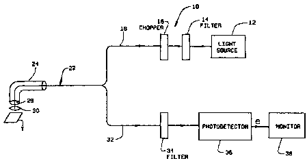
Referring specifically to the drawings, Figure 1 is a schematic view of an
apparatus 10 for detecting cancer in vitro or in vivo using cellular
autofluorescence. Apparatus 10 includes a light source 12, such as a Xenon arc
lamp or a laser, powered by a conventional power source. A first optical
filter
14 with a narrow bandwidth of about 125 nm, configured to pass light at a
wavelength in a range of about 200 - 329 nm is positioned in the path of the
light
beam produced by light source 12. In one embodiment, first optical filter 14
has
a narrow bandwidth of about 35 nm and is configured to pass light at a
wavelength in a range of about 280-315 nm. The Might beam emerging from first
CA 02335246 2000-12-14
WO 99/65394 PCT/US98/17597
optical filter 14 passes through an optical chopper 16 which removes
wavelengths
of any background light. The light beam then passes through a two-way fiber
optic bundle 22, sometimes referred to herein as a probe, which is positioned
to
catch the light beam as it emerges from optical chopper 16. The two-way fiber
S optic bundle 22 has a sampling end 28, and comprises two groups of optic
fibers. .
A first group of optic fibers 18 transmits light from source of white light 12
to
a tissue T. A second group of optic fibers 32 transmits a light sample back
from
tissue T for analysis.
The two optical fiber groups of two-way fiber optic probe 22 are
randomly intermeshed. Two-way fiber optic probe 22 is less than about 2.5 rnm
in diameter and is Iong enough to pass through the biopsy channel of an
endoscope, e.g., about 1 - 2 m in length. Specifically, probe 22 is configured
to
pass through the biopsy channel of a conventional endoscope 24, such as the
endoscopes commonly used to examine the gastrointestinal tract or the lungs.
In
an alternate embodiment, two-way fiber optic bindle 22 may be passed through
a needle or trocar to obtain measurements of cellular autofluorescence
intensity
from solid masses or organs such as breast, liver or pancreas.
A lens system 30 is positioned between sannpling end 28 of two-way fiber
optic bundle 22 and tissue T. Lens system 30 is provided to avoid direct
contact
between the tissue and probe 22. Light emerging from tissue T, including
emissions of cellular autofluorescence and reflLected and scattered light, is
collected by lens system 30 to form a light sample.
The light sample is directed to sampling end 28 of two-way fiber optic
bundle 22. The light sample is then transmitted back through two-way fiber
optic
bundle 22, along second group of optic fibers 32, from sampling end 28 to a
second optical filter 34. Second optical filter 34 has a narrow bandwidth of
about
20 nm, configured to pass light at a wavelength ~of about 320 - 340 nm, and is
positioned in the path ~of the light sample transmitted back from tissue T. A
photodetector 36 is positioned to collect the liglht sample as it emerges from
CA 02335246 2000-12-14
WO 99165394 PCT/US98/17597
6
second optical filter 34. Photodetector 36 is configured to measure the
intensity
of the light sample across wavelengths varying from about 320 nm to about 340
nm.
Photodetector 36 generates an electrical output signal a whose magnitude
is proportional to the intensity of the light sample: at a wavelength of about
330
nm. Electrical output signal a is amplified and displayed on a monitor 38 as a
wave form or meter response. The intensity of cellular autofluorescence in
tissue
T may thus be noted and compared to the intensity of cellular autofluorescence
at about 330 nm in a tissue whose condition is known, such as a cancerous, pre-
cancerous or normal tissue. The presence of cancerous cells is indicated by an
increase, relative to normal tissue, in intensity of cellular autofluorescence
at an
emission wavelength of about 330 nm. A ratiio of the intensity of cellular
autofluorescence in the tissue F~ to the intensity oif cellular
autofluorescence in a
known normal sample Fn may be constructed. The: greater the value of F~/F",
the
more severe the degree of cancer or malignancy.
Figure 2 is a schematic view of an apparatus 100 for real time detection
of cancer in vitro or in vivo using cellular autofluorescence and video
imaging
technology. Apparatus 100 includes a source of white light 102, such as a
Xenon
arc lamp or a laser, is powered by a conventional, power source and produces a
beam of light. The light beam then passes throul;h a first group of optic
fibers
104 of a two-way fiber optic bundle 108 which is positioned to catch the light
beam as it emerges from white light source 102. The first group of optic
fibers
104 transmits the light beam to a tissue T. Two-way optic fiber bundle 108
passes through a conventional endoscope 109. In alternate embodiments, the
two-way fiber optic bundle may pass through a large-bore needle or trocar. . A
lens system 110 is part of the endoscope 109 and interposed between tissue T
and
two-way fiber optic bundle 108. It is positioned t~o catch reflected and
scattered
light from tissue T, as well as emissions of cellular autofluorescence, to
form a
CA 02335246 2000-12-14
WO 99165394 PCT/US98117597
7
light sample from tissue T. A second group of optic fibers 106 in two-way
fiber
optic bundle 108 transmits the light sample back from tissue T.
The light sample transmitted along second group of optic fibers 106 of
two-way fiber optic bundle 108 is directed into an image acquisition module
114
by a lens 1 I2. Image acquisition module 114 uses a standard optical device
such
as a prism or dichromatic mirror to split the light sample into two beams of
light
b1 and b2, each comprising identical wavelengths,. Light beam bl is
transmitted
to a conventional video detector 116 which produces a video signal cl
representative of the standard visual image obtained from tissue T with
endoscope
109 and lens system 110. Light beam b2 is transmitted to an optical filter 118
with a bandwidth of about 20 nm at about 330 nm" Light beam b2 then impinges
on an image intensifier 120, and then a charge-coupled device or CCD 122 which
produces a second video signal c2. Video sigr~a.l c2 is representative of the
intensity of cellular autofluorescence emitted from tissue T. Video signal c2
is
1S color-coded according to the intensity of cellular autofluorescence to
visually
represent different stages of malignancy of the lesian. Video signals cl and
c2
are then directed via conventional cable means to a computerized image
controller
124 which combines the two video signals cl and c2 into a single signal which
represents the superimposition of the image represented by c2 onto the image
represented by cl . The combined signal is then directed to a standard color
video
monitor 126 for display of the combined images.
Figure 3 is a flow chart illustrating a method 150 for utilizing
autofluorescence to detect pre-cancer, early cancer, cancer, and dysplasia.
Method 150 includes exposing a first tissue to a Iig;ht beam 152 which excites
the
tissue and results in an emission of cellular autofluorescence at a wavelength
of
about 330 nm. In this embodiment, the first tissue is being examined for the
detection of cancer. After exposure of the tissue to the beam of light, the
intensity of cellular autofluorescence emitted from the tissue is measured, at
a
wavelength of about 330 nm, using a standard photodetector 154.
CA 02335246 2000-12-14
WO 99/65394 PCT/US98/17597
8
In parallel, or in series, with steps 152 and 154, a second tissue whose
condition is known as normal, pre-cancerous, or cancerous also is examined.
Particularly, the second tissue is exposed to a light beam 156 which excites
the
tissue and results in an emission of cellular autofluorescence at a wavelength
of
about 330 nm. After exposure of the tissue to the; beam of light, the
intensity of
cellular autofluorescence emitted from the tissue its measured, at a
wavelength of
about 330 nm, using a standard photodetector 158.
The intensity measurements from the first and second tissues are then
compared 160. The intensity measurements obtained from the second tissue,
which is of known condition, serves as a standard. Using the results of the
comparison, the condition of the first tissue can be determined 162.
Method I50 may be practiced in vivo using a two-way fiber optic bundle
passed through the biopsy channel of a conventional endoscope, as described
above in connection with Figures 1 and 2. Alternatively, the first and second
tissues may be collected tissue samples and metr~od 150 may be practiced in a
laboratory. In addition, method 150 could be practiced in connection with the
use of a charge-coupled device and video imaging equipment. With such devices.
and equipment, and at steps 154 and 158, the intensity of the autofluorescence
could be visually represented in a real time video image. Real time video
scanning of cellular autofluorescence would allow large areas of tissue to be
scanned both in vitro and in vivo.
Figure 4 is a schematic illustration of an ;apparatus 200 for detection of
cancer using cellular autofluorescence in accordance with yet another
embodiment
of the present invention: Apparatus 200 includes a light source 202 which may
be a component of a conventional endoscopic illumination system. Light source
may, for example, be a Xenon lamp or a source of laser energy. Source 202 is
coupled to a lens system 204 by a optical fiber bundle 206. Lens system 204 is
focused on a tissue T, such as a tissue, a tissue sample, an organ, or cells.
A lens
system 208 is positioned to collect light from tissue T, and lens system 208
is
CA 02335246 2000-12-14
WO 99165394 PCT/IJS98117597
9
coupled to an image acquisition module 210 by an optical fiber bundle 212. At
image module 210, the light received from bundle 212 is split using a splitter
such as a dichromatic mirror or a prism to produce two identical beams B 1 and
Bz.
Light beam B1 is transmitted to a convenxionai video detector 214 which .
produces a video signal S1 representative of the standard visual image
obtained
from tissue T. Light beam B2 is transmitted to a~n optical filter 216 with a
band
width of about 125 nm which allows wavelenl;ths of about 290 nm to pass
through. In one embodiment, optical filter 216 alllows wavelengths in the
range
of about 200 nm to about 329 nm to pass through. In an alternative embodiment,
the band width of optical filter 216 is about 35 nrn which allows wavelengths
in
a range of about 280 - 315 nm to pass through. Liight beam B2 then impinges on
an image intensifier 218, and then a charge-coupled device or CCD 220 which
produces a second video signal S2. Video signal S2 is representative of the
intensity of cellular autofluorescence emitted frorn tissue T.
Signals S1 and S2 are supplied to a computerized image controller 222
coupled to a display 224. The autofluorescence image from signal S2 could be
color coded (i.e., different colors represent different grades of fluorescence
intensities, and hence stages of malignancy) and superimposed on the standard
endoscopic image from signal S 1. The intensity of cellular fluorescence would
be stronger in malignant tissues than in normal tissue of the same organ, for
example. The intensity of malignant areas also would be greater than that in
dysplastic areas, which should be stronger than that in normal areas. If a
laser
source is used as light source 202, a gating rnE;chanism could be utilized to
rapidly and alternately illuminate the sample with. white light (for routine
video
endoscopy) and the laser (for fluorescence imaging).
Using the above described methods and apparatus, fluorescence images
can be obtained during endoscopy, from gastrointestinal organs, lungs,
bladder,
ureters, cervix, skin and bile ducts, and pancreatic ducts. Narrow caliber
CA 02335246 2000-12-14
WO 99165394 PCT/US9$/17597
endoscopes can be passed through the biopsy ch~umels of larger endoscopes to
obtain cellular fluorescence imaging from organs such as ureters, bile and
pancreatic ducts, or may be passed through a large bore needle or trocar to
examine solid organs such as the liver, pancreas, breast, prostrate, or other
5 masses.
Measuring the intensity of the light sample: at an emission wavelength of
about 330 nm enables detection of pre-cancerous and cancerous cells.
Specifically, the intensity of the light sample at 3?~0 nm increases
systematically
with the progression of cancer from normal to cancerous tissue. In addition,
at
10 the wavelengths identified above, extracellular changes which are non-
specific to
cancer are excluded and therefore, only the cellular changes are detected. It
is
believed that the cell specific fluorescence originates from membranous
structures
in cells containing the amino acid Tryptophan.
From the preceding description of various embodiments of the present
invention, it is evident that the objects of the invention are attained.
Although the
invention has been described and illustrated in detail, it is to be clearly
understood that the same is intended by way of illustration and example only
and
is not to be taken by way of limitation. Accordingly, the spirit and scope of
the
invention are to be limited only by the terms of th.e appended claims.