Note : Les descriptions sont présentées dans la langue officielle dans laquelle elles ont été soumises.
CA 02342809 2001-03-28
- 1 -
GAS TURBINE AND REPAIR METHOD THEREFOR
BACKGROUND OF THE INVENTION
The present invention relates to a combustor
that is a component of a gas turbine, more particular-
ly, relates to a transition piece for transferring a
working fluid having been burnt to an annular flow path
of a gas turbine through a cylindrical liner and a
repair method therefor.
As a method for repairing a transition piece
of a combustor, a method in which cracks are repaired
and residual stress is relieved and wear resistance is
improved by combining shot peening and solution heat
treatment has been known and has been disclosed in JP-
A-6-288549 specification, for example.
However, it has been demanded that the above-
described prior art be improved more to achieve high
efficiency for energy saving, increased strength and
prolonged service life of an outlet portion of com-
bustor, and decreased repair and inspection manpower.
SUMMARY OF THE INVENTION
An object of the present invention is to
achieve energy saving, increased strength, prolonged
service life, and decreased repair and inspection
manpower while facilitating the replacement and repair
of a transition piece of a combustor.
CA 02342809 2001-03-28
- 2 -
To attain the above object, the present
invention provides a gas turbine comprising a com-
pressor for compressing air as a working fluid, a
combustor for producing combustion gas by mixing fuel
with the compressed air, and a turbine for generating a
rotational power at the time of expansion of the com-
bustion gas, and further comprising a cylindrical
liner; a transition piece for transferring the working
fluid from the liner to the.turbine; an outlet portion
of the transition piece, which has a region parallel
with the direction of rotating shaft of the turbine;
cooling holes formed in the region so that the
intervals thereof are lengthened partially; and a
picture frame portion provided to secure stiffness near
the outlet of the outlet portion.
Also, the present invention provides a repair
method for a gas turbine having a compressor for com-
pressing air as a working fluid, a combustor for
producing combustion gas by mixing fuel with the com-
pressed air, and a turbine for generating a rotational
power at the time of expansion of the combustion gas,
comprising providing, at an outlet portion of a
transition piece for transferring the working fluid to
the turbine, a region parallel with the direction of
rotating shaft of the turbine, cooling holes formed in
the region so that the intervals thereof are lengthened
partially, and a picture frame portion to secure
stiffness near the outlet of the outlet portion;
CA 02342809 2001-03-28
- 3 -
cutting the outlet portion in a portion where the
intervals of the cooling holes are lengthened partially
and separating the picture frame portion, and welding a
picture frame portion prepared in advance in the cut
portion for replacement.
Further, in the repair method described
above, it is preferable that deterioration in the cut
portion be evaluated, and the surface temperature state
of the outlet portion be estimated, whereby the
arrangement of the cooling holes be determined.
Further, in the repair method described
above, the picture frame portion prepared in advance is
preferably another picture frame portion that has been
repaired and is reused.
Further, in the repair method described
above, the length of the whole of the transition piece
is preferably adjusted by grinding the end face of the
cut-off picture frame portion.
Further, in the repair method described
above, the picture frame portion is preferably welded
to the cut portion via a connecting member.
Further, in the gas turbine described above,
the picture frame portion is preferably welded via a
connecting member formed with cooling holes.
BRIEF DESCRIPTION OF THE DRAWINGS
Fig. 1 is a sectional view showing a
transition piece construction of one embodiment in
CA 02342809 2001-03-28
- 4 -
accordance with the present invention;
Fig. 2 is a sectional view showing a
construction of a conventional gas turbine;
Fig. 3 is views showing a repair method
(procedure) for a transition piece of one embodiment in
accordance with the present invention;
Fig. 4 is sectional views showing an outlet
portion of a transition piece of one embodiment in
accordance with the present invention;
Fig. 5 is views showing a repair method
(procedure) for a transition piece of another
embodiment in accordance with the present invention;
Fig. 6 is views showing a repair method
(procedure) for a transition piece of still another
embodiment in accordance with the present invention;
Fig. 7 is views showing a repair method
(procedure) for a transition piece of still another
embodiment in accordance with the present invention;
Fig. 8 is sectional views showing a picture
frame portion of one embodiment in accordance with the
present invention;
Fig. 9 is views showing formation of a
connecting member of one embodiment in accordance with
the present invention;
Fig. 10 is a sectional view showing intervals
between cooling holes of one embodiment in accordance
with the present invention;
Fig. 11 is a side view showing arrangement of
CA 02342809 2001-03-28
- 5 -
cooling holes of one embodiment in accordance with the
present invention;
Fig. 12 is views showing a repair method
(procedure) for a transition piece of still another
embodiment in accordance with the present invention;
Fig. 13 is views showing a repair method
(procedure) for a transition piece of still another
embodiment in accordance with the present invention;
Fig. 14 is views showing a repair method
(procedure) for a transition piece of still another
embodiment in accordance with the present invention;
Fig. 15 is views showing a repair method
(procedure) for a transition piece of still another
embodiment in accordance with the present invention;
Fig. 16 is views showing a repair method
(procedure) for a transition piece of still another
embodiment in accordance with the present invention;
and
Fig. 17 is views showing a repair method
(procedure) for a transition piece of still another
embodiment in accordance with the present invention.
PREFERRED EMBODIMENTS OF THE INVENTION
Embodiments of the present invention will
now be described with reference to the accompanying
drawings.
Fig. 2 is a sectional view showing a general
construction of a gas turbine. The gas turbine mainly
CA 02342809 2001-03-28
- 6 -
comprises a compressor 1, a combustor 2 and a turbine
3. The compressor 1 adiabatically compresses air
sucked from the atmosphere into a gas path 4 as a
working fluid. The combustor 2 mixes fuel with the
compressed air supplied from the compressor 1 and burns
the mixture to produce a high-temperature and high-
pressure gas. The turbine 3 generates rotational power
when the combustion gas introduced from the combustor 2
expands. Exhaust from the turbine 3 is discharged into
the atmosphere. The remaining power, which is the
result of subtraction of the power for driving the
compressor 1 from the rotational power generated by the
turbine 3, is the power generated by the gas turbine,
which drives a generator.
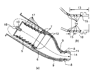
As shown in Fig. 1, the combustor 2 includes
a liner 5, a transition piece 6, and a flow sleeve 7
located on the outside of the liner 5 and the
transition piece 6 to accelerate cooling.
The transition piece 6 has an inlet of a
cylindrical shape and an outlet of an inverse trape-
zoidal shape. On the transition piece 6, an external
pressure caused by discharge air of the compressor 1
is exerted on the outside surface, and an internal
pressure caused by combustion gas is exerted on the
inside. Therefore, in comparison with the cylindrical
shape to which the pressure uniformly acts, the inverse
trapezoidal shape is more easily subjected to creep
deformation. Especially on the outlet side, the metal
CA 02342809 2001-03-28
- 7 -
temperature increases because the gas flow path area is
decreased as compared with the area on the inlet side
and therefore the outlet side is exposed to a high-
temperature environment, so that the creep deformation
tends to become still more remarkable. The outlet
portion exposed to a harsh environment in this manner
is most susceptible to damage including wear and
thermal fatigue of fitting portion and cracks caused by
creep, so that the outlet portion is supposed to be a
part that governs the service life of transition piece.
For a recent gas turbine facility, increased
output has been demanded to respond to an increase in
power demand in the summer, and also high efficiency
has been demanded to save energy.
As means for increasing the output, there is
a tendency for the annular flow path area, that is, the
size of the gas turbine to be increased. Also, as
means for increasing the efficiency, there is a
tendency for the pressure ratio of compressor to be
increased. Both of these means lead to an increase in
pressure load applied to the combustor, so that it is
expected that the combustor will be subjected to still
higher pressure load in the future. As a necessary
consequence, increased strength and prolonged service
life of the outlet portion are demanded.
Further in recent years, as a social demand
for a reduction in electric fee increases, it has been
of urgent necessity to reduce the power generation
CA 02342809 2001-03-28
_ g _
cost. In particular, the repair cost of high-
temperature parts such as the combustor and the moving
and stationary blades of turbine accounts for a large
percentage of the repair cost of gas turbine.
Therefore, a decrease in period and manpower of
periodic inspection has been demanded.
Further, since the load environment at an
actual power station varies, an initial cooling design
is sometimes not necessarily the optimum design.
Therefore, the cooling design properly corresponding to
the load environment is also of importance to the
prolonged service life of transition piece.
Referring to Fig. l, a working fluid 8
discharged from the compressor 1 is introduced to a gap
9 between the flow sleeve 7 and the transition piece 6.
The flow velocity of the working fluid 8 in the gap 9
increases, so that the cooling effect on the outside
surface of the transition piece 6 is enhanced.
In a diffusion combustion type combustor, in
which fuel is not mixed with air before combustion,
some of the working fluid 8 flowing through the gap 9
is introduced into the interior of the liner 5 through
cooling holes 17 formed in the outside surface of the
liner 5 to cool the liner 5, and the remainder thereof
flows into the interior of the liner 5 together with
fuel sprayed through a nozzle 10 to be used for
combustion.
As shown in Fig. 1, the fuel spray nozzle 10
CA 02342809 2001-03-28
_ g _
is inserted in an insertion portion 18 provided on the
inlet side of the liner 5. The working fluid 8 having
been burnt is discharged into an annular flow path of
the turbine 3 from the liner 5 through the transition
piece 6.
A plate spring 12 is welded to the outlet
side of the liner 5 and the liner 5 is inserted in the
transition piece 6. The transition piece 6 is
contained in the flow sleeve 7 with the liner 5
inserted in the inlet portion thereof via the plate
spring 12, and is supported on the inlet side by a
fitting portion that restrains only deformation in the
circumferential direction of an inlet cross section.
Also, near the outlet of the transition piece 6, a
picture frame portion 11 is provided to increase the
stiffness.
The flow sleeve 7 is supported on the inlet
side with the transition piece 6 by a fitting portion
that restrains only deformation in the circumferential
direction of inlet cross section, and likewise, it is
supported by a casing via a fitting portion that
restrains only deformation in the circumferential
direction of inlet cross section. On the outlet side
of the flow sleeve 7, the position of the flow sleeve 7
is determined by being connected with the casing
together with the transition piece 6.
As shown in (a) and (b) of Fig. 3, an outlet
portion 16 consisting of the picture frame portion 11
CA 02342809 2001-03-28
- 10 -
having ribs and a connecting member 19 for length
adjustment formed with cooling holes 14 is provided
with a region 13 parallel with the direction of a gas
turbine rotating shaft as shown in Fig. 1 (b).- The
intervals of the cooling holes 14 in the outlet portion
are lengthened partially. Thereby, the cutting
operation of the outlet portion 16 is made easy.
As shown in Fig. 3 (c), a damaged outlet
portion 16 is cut at a portion where the intervals of
the cooling holes 14 are lengthened partially to divide
the outlet portion 16 into the picture frame portion 11
having ribs and a region 21 with a constant plate
thickness. Wear and cracks occurred in the picture
frame portion 11 are repaired for reuse.
Further, a picture frame portion 11' and a
length adjusting connecting member 19' formed with
cooling holes 14 shown in Fig. 3(d) that have been
prepared in advance are welded to each other to form a
replacement outlet portion 16' as shown in Fig. 3(e).
Then, the outlet portion 16' is welded to the
transition piece 6 as shown in (f) and (g) of Fig. 3.
With the above-described repair method, only
the damaged outlet portion 16 is replaced rapidly, and
the cut-off outlet portion 16 is repaired separately.
Therefore, the replacement and repair cost can be
reduced, and the service life of the transition piece
and the whole of gas turbine can be prolonged.
When the replacement outlet portion 16' is
CA 02342809 2001-03-28
- 11 -
welded to the transition piece 6, the end face of the
connecting member 19' for length adjustment is
preferably ground to adjust the length of the whole of
transition piece.
As shown in (a) and (b) of Fig. 4, the outlet
portion 16 consists of the picture frame portion 11 and
the connecting member 19, and has a region parallel
with the gas turbine rotating shaft, and as shown in
Fig. 4(c), the intervals of the cooling holes 14 are
lengthened partially. Therefore, the cut-off of the
outlet portion 16 and the welding of the spare part
thereof are made easy.
Also, for the transition piece 6 once
replaced, as shown in Fig. 5(a), a damaged outlet
portion 16 is cut off in a cutting plane 20. The cut-
off outlet portion 16 shown in Fig. 5(b) is divided
into the picture frame portion 11 and the region 21
with a constant plate thickness, as shown in Fig. 5(c).
Wear and cracks occurred in the picture frame portion
11 may be repaired for reuse.
As shown in (a) and (b) of Fig. 6, a damaged
outlet portion 16 may be cut off at the cutting plane
20 and at a position between the picture frame portion
11 and the region 21 with a constant plate thickness
into the picture frame portion 11 having ribs and the
region 21 with a constant plate thickness. In this
example, as shown in (c) and (d) of Fig. 6, the
connecting member 19 formed with the cooling holes 14
CA 02342809 2001-03-28
- 12 -
is welded to the transition piece 6 and the picture
frame portion 11' is welded to the connecting member
19'.
Also, for the transition piece 6 once
replaced, as shown in (a) and (b) of Fig. 7, the outlet
portion 16 may be cut in the cutting plane 20 and at a
position between the picture frame portion 11 and the
region 21 with a constant plate thickness, and wear and
cracks occurred in the picture frame portion 11 may be
repaired to reuse the picture frame portion 11.
Fig. 8 shows sectional views of the picture
frame portion 11 constituting the outlet portion 16.
The cooling holes 14 may be formed at the whole
periphery of the picture frame portion 11, or may be
formed at the partial periphery thereof to effect
cooling efficiently. Also, as shown in Fig. 8(c), the
picture frame portion 11 is divided into several pieces
in the circumferential direction, and when wear and
cracks occurred in the picture frame portion 11 are
repaired, a divided piece 22 is cut off, and a
replacement divided piece 22' is welded. Thereby, the
work can be made easy, and the cost can be made
relatively low because the cooling holes 14 can be made
in the connecting member 19 after the plate has been
bent as shown in Fig. 9.
Further, since the load environment of an
actual turbine at an actual power station varies, the
initial cooling design is sometimes not necessarily the
CA 02342809 2001-03-28
- 13 -
optimum design. However, when the damaged outlet
portion 16 is cut off, the degree of damage on the
surface is evaluated, by which the arrangement of the
cooling holes 14 can be optimized in the direction of
the gas turbine rotating shaft as shown in Fig. 10 and
in the circumferential direction as shown in Fig. 11 to
restrain a local high-temperature zone.
Further, as shown in Fig. 12, in order to
restrain creep deformation, the plate thickness of the
transition piece 6 used continuously is preferably made
larger than that of the outlet portion 16 capable of
being replaced and repaired. In this case, for the
transition piece 6 once replaced, as shown in Fig.
13(a), the damaged outlet portion 16 is cut off in the
cutting plane 20 in which cutting operation is easy,
and further the cut-off outlet portion 16 shown in Fig.
13(b) is divided into the picture frame portion 11
having ribs and the region 21 with a constant plate
thickness as shown in Fig. 13(c). Thereby, wear and
cracks occurred in the picture frame portion 11 are
repaired to reuse the picture frame portion 11.
Further, as shown in Fig. 14, the outlet
portion 16 is cut off in the cutting plane 20, and is
divided into the picture frame portion 11 having ribs
and the region 21 with a constant plate thickness as
shown in (b) and (c) of Fig. 14, and a picture frame
portion 11 with a small outside diameter may be welded
instead.
CA 02342809 2001-03-28
- 14 -
As shown in Fig. 15, a connecting member 19'
formed with the cooling holes 14 and having an inside
diameter containing the transition piece 6 is welded to
the picture frame portion 11' to form a replacement
outlet portion 16', and the connecting member 19' may
be welded to the transition piece 6 as shown in Fig.
(d) .
Further, the outlet portion 16 is cut off in
the cutting plane 20 as shown in Fig. 16(a), and is
10 divided into the picture frame portion 11 having ribs
and the region 21 with a constant plate thickness as
shown in Fig. 16(c). A connecting member 19' having a
stepped inside diameter that is equal to the outside
diameter of the transition piece 6 and the picture
15 frame portion 11' is prepared, and the replacement
outlet portion 16' is welded.
With regard to a transition piece 6 which has
already exchanged or repaired, a connecting member 19
has an inner diameter at both ends thereof slightly
larger than an outer diameter of the transition piece 6
and a picture frame portion 11, and another inner
diameter at a central portion thereof substantially the
same as an inner diameter of the transition piece 6 and
the picture frame portion 11. As shown in Fig. 17(a),
the connecting member 19 for length adjustment is cut.
As shown in Fig. 17(b), the cut outlet portion 16 is
divided into a picture frame portion 11 having ribs and
the cut connecting member 19. Wear damage, cracks and
CA 02342809 2001-03-28
- 15 -
the like resulted on the picture frame portion 11 are
repaired for reuse.
Further, as shown in Fig. 17(c), another
picture frame portion 11' and another connecting member
19' which are manufactured in advance are welded to
each other and then is welded to the transition piece 6
as shown in Fig. 17(d).
According to the present invention, the cut-
off of the outlet portion from the transition piece can
be made easy, the replacement and repair of outlet
portion can be made easy, and energy saving, increased
strength, prolonged service life, and decreased repair
and inspection manpower can be achieved.