Sélection de la langue

Search

Sommaire du brevet 2345039 

Énoncé de désistement de responsabilité concernant l'information provenant de tiers

Une partie des informations de ce site Web a été fournie par des sources externes. Le gouvernement du Canada n'assume aucune responsabilité concernant la précision, l'actualité ou la fiabilité des informations fournies par les sources externes. Les utilisateurs qui désirent employer cette information devraient consulter directement la source des informations. Le contenu fourni par les sources externes n'est pas assujetti aux exigences sur les langues officielles, la protection des renseignements personnels et l'accessibilité.

Disponibilité de l'Abrégé et des Revendications

L'apparition de différences dans le texte et l'image des Revendications et de l'Abrégé dépend du moment auquel le document est publié. Les textes des Revendications et de l'Abrégé sont affichés :

  • lorsque la demande peut être examinée par le public;
  • lorsque le brevet est émis (délivrance).
(12) Brevet: (11) CA 2345039
(54) Titre français: SYSTEME DE MELANGE SERVANT A INTRODUIRE ET A DISPERSER DES GAZ DANS DES LIQUIDES
(54) Titre anglais: MIXING SYSTEM FOR INTRODUCING AND DISPERSING GAS INTO LIQUIDS
Statut: Durée expirée - au-delà du délai suivant l'octroi
Données bibliographiques
(51) Classification internationale des brevets (CIB):
(72) Inventeurs :
  • GIGAS, BERND (Etats-Unis d'Amérique)
(73) Titulaires :
  • SPX FLOW, INC.
(71) Demandeurs :
  • SPX FLOW, INC. (Etats-Unis d'Amérique)
(74) Agent: ROBIC AGENCE PI S.E.C./ROBIC IP AGENCY LP
(74) Co-agent:
(45) Délivré: 2008-03-18
(86) Date de dépôt PCT: 1999-09-22
(87) Mise à la disponibilité du public: 2000-03-30
Requête d'examen: 2004-05-20
Licence disponible: S.O.
Cédé au domaine public: S.O.
(25) Langue des documents déposés: Anglais

Traité de coopération en matière de brevets (PCT): Oui
(86) Numéro de la demande PCT: PCT/US1999/021761
(87) Numéro de publication internationale PCT: US1999021761
(85) Entrée nationale: 2001-03-21

(30) Données de priorité de la demande:
Numéro de la demande Pays / territoire Date
09/159,531 (Etats-Unis d'Amérique) 1998-09-23

Abrégés

Abrégé français

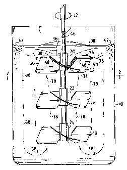
Système de mélange mettant en application des hélices de pompage (14, 16, 18) à écoulement axial qui entraînent le gaz vers l'intérieur du liquide à la fois en surface (12) et sous la surface par attraction du gaz au-dessous de la surface, ce gaz étant alors dispersé à l'intérieur de la circulation produite par les hélices (14, 16, 18). Des tubes (48) sont situés sur les côtés aspiration des pales d'hélice (14, 16, 18) et constituent des sorties de gaz à proximité des extrémités (50) des pales (14, 16, 18). Ces tubes (48) peuvent s'étendre le long de l'arbre au-dessus de la surface ou vers l'intérieur d'un arbre creux possédant une ouverture de respiration (46) au-dessus de la surface (12). La rotation des hélices (14, 16, 18) produit une aspiration au niveau des sorties des tubes, ce qui attire le gaz à l'intérieur du liquide, tandis que la circulation vers le haut produit des turbulences de surface servant à entraîner le gaz.


Abrégé anglais


A mixing system utilizes up pumping axial flow impellers
(14, 16, 18) which entrain gas into the liquid both at the surface
(12) and below the surface by induction to draw gas down
below the surface where it is dispersed into the circulation
produced by the impellers (14, 16, 18). Tubes (48) are disposed
on the suction sides of the impeller blades (14, 16, 18), and
provide gas outlets near the tips (50) of the blades (14, 16, 18).
The tubes (48) may extend along the shaft above the surface
or into a hollow shaft having a breathing opening (46) above
the surface (12). The rotation of the impellers (14, 16, 18)
produces a suction at the tube outlets to draw gas into the liquid
while the upward circulation produces surface turbulence for gas
entrainment.

Revendications

Note : Les revendications sont présentées dans la langue officielle dans laquelle elles ont été soumises.


6
WHAT IS CLAIMED IS:
1. A mixing system for circulating a liquid in a tank while introducing gas
into
said liquid which comprises an impeller which provides circulation upwardly
towards a liquid gas interface in said tank and downwardly away from said
interface, said impeller being disposed below said interface and being exposed
along a free precirculation path to said interface and being spaced
sufficiently
close to said interface to create a swell which entrains said gas above said
interface, and at least one conduit rotatable with said impeller and
communicating said gas with said liquid in said circulation.
2. The system according to claim 1, wherein the gas above said interface is
at a pressure greater than a pressure in a region in said tank with which said
conduit provides said communication, thereby sparging said gas by induction
into said liquid.
3. The system according to claim 2, wherein said impeller has a plurality of
blades mounted for rotation on a shaft, each of said blades having a tip and
opposite edges extending radially from said shaft with trailing and leading
ones
of said edges being respectively closer and further away from said interface,
said impeller rotation in said liquid providing said region in the vicinity of
said
tips.
4. The system according to claim 3, wherein said leading and trailing edges
are disposed successively in the direction of rotation of said impeller and
said
blades are pitched so that said leading edges arc further from said interface
than
said trailing edges to direct said circulation upwardly toward said interface
in the
discharge flow from said impeller.
5. The system according to claim 3, wherein said impeller is an up pumping
axial flow impeller.

7
6. The system according to claim 3, wherein said conduit has an outlet at
one end thereof approximately at said tips.
7. The system according to claim 4, wherein said conduit ascends along the
trailing edge of said blades to said tip bringing an open end of said conduit
and
providing an outlet for said gas approximately at said tip.
8. The system according to claim 7, wherein said conduit extends along said
shaft to another open end thereof above said interface providing an inlet for
said
gas.
9. The system according to claim 7, wherein said shaft has an opening
extending axially thereof and providing an inlet for said gas at a breather
hole
above said interface, said opening in said shaft providing a portion of said
conduit, and a tube connected to said opening and extending to approximately
said tip and providing the outlet for said gas.
10. The system according to claim 8, wherein said impeller has a plurality of
said blades, said conduit comprising a plurality of tubes extending along the
trailing edges of said blades to approximately the tips of said blades, said
tubes
extending along said shaft above said interface to open ends thereof.
11. The system according to claim 9, wherein said shaft has an opening
extending axially along said shaft from a breather hole above said interface
and
openings above said impeller, said impeller having a plurality of blades, said
conduit comprising a plurality of tubes each extending to said shaft opening
to
said openings below said impeller and from said openings below said impeller
along suction sides of said blades and along the trailing edges of said blades
to
opposite ends providing gas outlets approximately at said tips.

8
12. The system according to claim 3, wherein said impeller is spaced from
said interface as such that said impeller is less than from about 1D to at
said
interface, where D is the diameter of said impeller.
13. The system according to claim 3, wherein said impeller is an unshrouded,
up pumping axial flow impeller wherein the volume between said impeller and
said tank is open at least to the edges of any baffles along an inside wall of
said
tank.
14. The system according to claim 3, wherein said impeller is one of a
plurality of up pumping axial flow impellers mounted on said shaft and spaced
successively further from said interface.
15. The system according to claim 13, wherein said impeller is one of a
plurality of up pumping axial flow impellers on said shaft.
16. The system according to claim 15, wherein said plurality of impellers is
at
least 3 impellers spaced approximately equal distances apart from each other.

Description

Note : Les descriptions sont présentées dans la langue officielle dans laquelle elles ont été soumises.


CA 02345039 2001-03-21
WO 00/16885 PCT/US99/21761
MIXING SYSTEM FOR INTRODUCING
AND DISPERSING GAS INTO LIQUIDS
Description
The present invention relates to mixing systems for introducing or sparging
gas into
liquids in a tank. By liquids is meant to include liquid suspensions and
slurries. Where the gas
is air, such systems are sometimes called aeration systems. The system
provided by the
invention is effective for mass conversion of the gaseous phase into a liquid
phase in order to
carry out or promote reactions in various chemical and biological processes.
Dispersion or sparging of gas into a liquid medium in a tank using axial flow
impellers,
where the gas is released below the surface under pressure via a sparged pipe
or ring, is
described in Weetman, U.S. Patent 4,882,098 issued November 21, 1989 and
Weetman and
Howk, U.S. Patent 4,896,971 issued January 30, 1990. A gas liquid mixing
system has also
been proposed which uses a down pumping impeller within a draft tube shrouding
the impeller
to create a vortex for surface gas entrainment in the vortex while gas is
introduced by suction
created by the impeller. See Litz, et al, U.S. 4,919,849, April 24, 1990.
Reliance on the
vortex for surface gas entrainment may increase the amount of gas introduced
into the liquid
over a varying range of liquid levels, but the system remains sensitive to
liquid level changes
and lacks the desired constancy of mass transfer over a range of liquid
levels. These may
include levels from where the surface of the liquid (the gas liquid
interphase) intersects the
impeller, leaving the impeller at the surface, to where the impeller is
completely submerged.
The efficiency of mass transfer, which may be measured by the mass transfer
coefficient kLa
should, desirably, remain essentially constant over the full range of liquid
levels which may be
encountered in the operation of the system.
It is a feature of the present invention to provide a mixing system for
aeration or sparging
of gas into liquids where dependence of gas introduction and efficiency of gas
transfer is
maintained essentially constant. In other words where the variation in mass
transfer coefficient
kLa with liquid level is reduced.
As a matter of general background to the art of gas to liquid transfer and
mixing,
reference may be had to the following U.S. patents: Kingsley 5,451,349, and
5,451,348,
September 19, 1995; Cozma, et al, 5,431,860, July 11, 1995; Middleton, et al,
5,198,156,

CA 02345039 2006-08-23
2
March 30, 1993; Weise, et al, 5,009,816, April 23, 1991; Litz, et al,
4,900,480, February 13,
1990; Litz, RE32562, December 15, 1987; Kwak, 4,290,885, September 22, 1981;
Wang,
4,259,267, March 31, 1981; and Reimann, 3,953,326, April 27, 1976.
It has been discovered in accordance with the invention that a substantially
axial and
upwardly directed flow pattern from an axial flow impeller enables gas to be
introduced by
surface entrainment without the creation of a vortex and also enables gas to
be induced by
suction created by the impeller below the surface in the vicinity of the
impeller so as to be
dispersed in the circulation created by the impeller. The induction of gas is
preferably carried
out by extending conduits in the form of tubes having outlets in the vicinity
of the tips of the
impellers, preferably close to the trailing edge of the impeller as it
rotates. These conduits
rotate with the impeller and communicates with gas above the liquid surface
level by extending
above the surface, either directly or via a hollow opening in the shaft which
rotates the impeller.
The mixing system so configured has been found to be less sensitive to
variations in surface
level and more constant in terms of the mass transfer efficiency, for example,
as expressed by
the mass transfer coefficient, kLa, than systems relying on surface
entrainment alone, gas
induction alone or gas induction with surface entrainment in a vortex formed
by a down-pumping
impeller.
Accordingly, it is the principal object of the invention to provide an
improved mixing system for sparging and dispersion of gas into liquids.
It is another object of the invention to provide an improved mixing system
for circulating a liquid in a tank while introducing gas into the liquid which
comprises
- an impeller which provides circulation upwardly towards a liquid gas
interface in the tank and downwardly away from the interface, the impeller
being
disposed below the interface and being exposed along a free precirculation
path
to the interface and being spaced sufficiently close to the interface to
create a
swell which entrains the gas above the interface, and
- at least one conduit rotatable with the impeller and communicating the
gas with the liquid in the circulation.
It is another object of the invention to provide an improved mixing system for
gas liquid
transfer having a mass transfer coefficient, kLa, wherein the sensitivity to
liquid variations is
controlled without lowering the efficiency of the mixing system.
lt is another object of the present invention to provide an improved mixing
system for
sparging and dispersing of gas into liquids utilizing induction of gas due to
suction created by

CA 02345039 2006-08-23
2a
a rotating impeller, where the impeller may be located in close proximity to
the surface thereby
requiring less power to obtain tip speeds for creating suction to induce gas
into the liquid, while
promoting the entrainment of gas into liquid at the surface by causing the
surface to well up and
become turbulent.
Briefly described, a mixing system for circulating a liquid in a tank while
introducing gas
into the liquid utilizes an impeller which provides an up-flowing circulation
in an axial direction,

CA 02345039 2001-03-21
WO 00/16885 PCT/US99/21761
3
that is an up-pumping axial flow impeller. The circulation continues upwardly
and along the gas
liquid interface in the tank and downwardly away from the interface along the
inside wall and
bottom of the tank, recirculating upwardly into the impeller. There may be a
plurality of axial
flow up pumping impellers on the shaft spaced from each other successively
away from the
bottom of the tank. These impellers may be pitched blade turbines or air foil
impellers. The
design of such impellers may be as described in the above referenced patents
or the impellers
may be of the type known by Model A-340 sold by Lightnin Mixers of Mt. Read
Boulevard,
Rochester, New York 14611, U.S.A. The liquid level may change, for example, by
reason of
withdrawal of liquid from the tank (drainage) or otherwise, so that the level
may be at the
impeller or up to about one impeller diameter away from the surface. A
conduit, preferably,
tubes, which extend along the suction side of the impeller and have outlets
where the suction
created by the impeller is optimum (approximately at the tips and near the
trailing edges of the
impeller) rotate with the impeller. These tubes extend to breathing openings
above the liquid
surface so as to be operative to induce gas into the liquid and out of the
tubes, where the gas
is dispersed into circulation from the impeller. Gas entrainment occurs
because of swelling and
turbulence created by the upward flow from the impeller at the surface and
especially turbulence
at the inside wall of the tank. The mixing system provides efficient gas
introduction or sparging
as may be measured by the mass transfer coefficient kLa of the system.
The foregoing and other objects, features and advantages of the invention, as
well as
presently preferred embodiments thereof, will become more apparent from a
reading of the
following description in connection with the accompanying drawings wherein:
FIG 1 is an elevational view of a mixing system embodying the invention;
FIG 2 is a plan view taken along the line 2-2 in the direction of the arrows
in FIG 1;
FIG 3 is an elevational view similar to FIG 1 showing another embodiment of
the
invention;
FIG 4 is a plot illustrating the variation of kLa with liquid level or the
distance between
the midline of the uppermost impeller in FIGs 1 and 2 and the surface of the
liquid (coverage).
Referring more particularly to FIGs 1 and 2 there is shown a tank 10
containing a liquid
(by which is meant to include liquid suspensions or slurries in the tank. The
liquid may fill the
tank to a level 12 when liquid is not circulating (the quiescent level 12).
The liquid is circulated

CA 02345039 2001-03-21
WO 00/16885 PCT/US99/21761 -
4
by three up-pumping axial flow impellers 14, 16 and 18, which are mounted via
hubs 20, 22,
and 24 on a shaft 26. This shaft is driven by a motor, and gear box so as to
rotate the impellers
at the speed to obtain the desired flow rate (cubic feet per minute) in the
tank.
The impellers are all identical and the illustrated impellers are three-bladed
impellers of
the type known as Model A340 which is available from Lightnin Mixers of
Rochester, New
York. The blade are made out of plates and are curved to present suction and
pressure sides,
respectively. The blades are pitched so that, in the direction of rotation
indicated by the arrows
32, the leading edges 34 of the blades are below or further away from the
surface 12 than the
trailing edges 36, thereof. Because of the blade angle or pitch and the
direction of rotation, the
impellers produce axial flow in the upward direction and are therefore, up-
pumping axial flow
impellers. The circulation in the tank is shown by the array of arrows 38.
This circulation
takes into account that the diameter of the impellers D is in the range from
0.4 to 0.65 of the
diameter of the tank 10, and also that the lower most impeller 18 is from
approximately 3/8 to
1 impeller diameter above the bottom of the tank. The axial upward flow from
the upper most
impeller 14 turns radial because of the surface or gas liquid interphase 12.
The upward flow
causes a swell 40 and the upward and radial flow causes turbulence, shown at
42 at the inside
wall of the tank 10. This swell and turbulence enhances gas entrainment into
the liquid at the
surface. The entrained gas is picked up by the circulation and carried around
the tank and
mixed and dispersed so as to effectively provide mass transfer from the
gaseous to the liquid
phase.
Sparging by induction is enhanced by the use of a conduit provided by an
opening or bore
44 in the shaft. Gas enters through a breathing hole 46 and continues into the
conduit portion
provided by tubes 48. These tubes have entry ends which extend through the
shafts into the
opening 44 and then on the suction sides, 28 of the blades, along the trailing
edges 36 to exits
near the tips 50. The exit ends of the tubes 48 may be chamfered at about 45
degrees to the axis
of the tubes so

CA 02345039 2006-08-23
impeller where the bubbles circulate for mass transfer for the liquid phase in
the
tanks.
The impellers are not shrouded but nevertheless provide circulation
sufficient for efficient mass transfer. Indeed, according to a preferred
embodiment of the invention, the impeller of the system may be an unshrouded,
up pumping axial flow impeller wherein the volume between the impeller and the
tank is open at least to the edges of any baffles along an inside wall of the
tank.
The system shown in FIG. 3 is like the systems shown in FIGS. 1 and 2,
however, the
tubes 48 extend along the side of the hub 20 and the shaft 26 to locations
above the level of the
liquid 12. This simplifies the design by eliminating the need for a hollow
shaft 26. Moreover,
the tubes enhance the turbulence around the shaft and promote the efficiency
of gas to liquid
mass transfer.
Referring to FIG. 4, there are shown two curves which illustrate the increase
and
constancy of the mass transfer coefficient kLa with variations in liquid level
or coverage over
the impeller. The coverage may be measured from the midline of the impeller or
from the upper
most or trailing edge.
From the foregoing description, it will be apparent that there has been
provided an
improved mixing system for gas to liquid phase transfer which utilizes up-
pumping impellers and
surface gas induction. Variations on modifications in the herein described
system, within the
scope of the invention will undoubtedly suggest themselves to those skilled in
the art.
Accordingly, the foregoing description should be taken as illustrative and not
in a limiting sense.

Dessin représentatif
Une figure unique qui représente un dessin illustrant l'invention.
États administratifs

2024-08-01 : Dans le cadre de la transition vers les Brevets de nouvelle génération (BNG), la base de données sur les brevets canadiens (BDBC) contient désormais un Historique d'événement plus détaillé, qui reproduit le Journal des événements de notre nouvelle solution interne.

Veuillez noter que les événements débutant par « Inactive : » se réfèrent à des événements qui ne sont plus utilisés dans notre nouvelle solution interne.

Pour une meilleure compréhension de l'état de la demande ou brevet qui figure sur cette page, la rubrique Mise en garde , et les descriptions de Brevet , Historique d'événement , Taxes périodiques et Historique des paiements devraient être consultées.

Historique d'événement

Description Date
Inactive : CIB expirée 2022-01-01
Représentant commun nommé 2019-10-30
Inactive : Périmé (brevet - nouvelle loi) 2019-09-23
Requête pour le changement d'adresse ou de mode de correspondance reçue 2018-12-04
Lettre envoyée 2015-06-08
Inactive : Correspondance - Transfert 2015-05-26
Inactive : Transferts multiples 2015-05-22
Lettre envoyée 2015-05-04
Inactive : Transfert individuel 2015-04-15
Lettre envoyée 2015-04-07
Inactive : Correspondance - TME 2010-08-10
Accordé par délivrance 2008-03-18
Inactive : Page couverture publiée 2008-03-17
Préoctroi 2007-12-28
Inactive : Taxe finale reçue 2007-12-28
Un avis d'acceptation est envoyé 2007-11-13
Lettre envoyée 2007-11-13
Inactive : CIB enlevée 2007-03-29
Inactive : Approuvée aux fins d'acceptation (AFA) 2007-03-21
Modification reçue - modification volontaire 2006-08-23
Inactive : Dem. de l'examinateur par.30(2) Règles 2006-03-27
Inactive : CIB de MCD 2006-03-12
Lettre envoyée 2004-06-01
Toutes les exigences pour l'examen - jugée conforme 2004-05-20
Exigences pour une requête d'examen - jugée conforme 2004-05-20
Requête d'examen reçue 2004-05-20
Inactive : Page couverture publiée 2001-06-13
Inactive : CIB en 1re position 2001-06-06
Inactive : Notice - Entrée phase nat. - Pas de RE 2001-05-29
Lettre envoyée 2001-05-29
Demande reçue - PCT 2001-05-25
Inactive : IPRP reçu 2001-03-22
Demande publiée (accessible au public) 2000-03-30

Historique d'abandonnement

Il n'y a pas d'historique d'abandonnement

Taxes périodiques

Le dernier paiement a été reçu le 2007-09-04

Avis : Si le paiement en totalité n'a pas été reçu au plus tard à la date indiquée, une taxe supplémentaire peut être imposée, soit une des taxes suivantes :

  • taxe de rétablissement ;
  • taxe pour paiement en souffrance ; ou
  • taxe additionnelle pour le renversement d'une péremption réputée.

Les taxes sur les brevets sont ajustées au 1er janvier de chaque année. Les montants ci-dessus sont les montants actuels s'ils sont reçus au plus tard le 31 décembre de l'année en cours.
Veuillez vous référer à la page web des taxes sur les brevets de l'OPIC pour voir tous les montants actuels des taxes.

Titulaires au dossier

Les titulaires actuels et antérieures au dossier sont affichés en ordre alphabétique.

Titulaires actuels au dossier
SPX FLOW, INC.
Titulaires antérieures au dossier
BERND GIGAS
Les propriétaires antérieurs qui ne figurent pas dans la liste des « Propriétaires au dossier » apparaîtront dans d'autres documents au dossier.
Documents

Pour visionner les fichiers sélectionnés, entrer le code reCAPTCHA :


Pour visualiser une image, cliquer sur un lien dans la colonne description du document. Pour télécharger l'image (les images), cliquer l'une ou plusieurs cases à cocher dans la première colonne et ensuite cliquer sur le bouton "Télécharger sélection en format PDF (archive Zip)" ou le bouton "Télécharger sélection (en un fichier PDF fusionné)".

Liste des documents de brevet publiés et non publiés sur la BDBC .

Si vous avez des difficultés à accéder au contenu, veuillez communiquer avec le Centre de services à la clientèle au 1-866-997-1936, ou envoyer un courriel au Centre de service à la clientèle de l'OPIC.


Description du
Document 
Date
(aaaa-mm-jj) 
Nombre de pages   Taille de l'image (Ko) 
Dessin représentatif 2001-06-12 1 10
Dessins 2001-03-20 4 84
Revendications 2001-03-20 3 105
Abrégé 2001-03-20 1 62
Description 2001-03-20 5 274
Description 2006-08-22 6 279
Revendications 2006-08-22 3 106
Revendications 2001-03-21 3 95
Dessin représentatif 2008-02-14 1 13
Rappel de taxe de maintien due 2001-05-28 1 111
Avis d'entree dans la phase nationale 2001-05-28 1 193
Courtoisie - Certificat d'enregistrement (document(s) connexe(s)) 2001-05-28 1 113
Rappel - requête d'examen 2004-05-25 1 116
Accusé de réception de la requête d'examen 2004-05-31 1 176
Avis du commissaire - Demande jugée acceptable 2007-11-12 1 164
Courtoisie - Certificat d'enregistrement (document(s) connexe(s)) 2015-04-06 1 101
Courtoisie - Certificat d'enregistrement (document(s) connexe(s)) 2015-05-03 1 103
PCT 2001-03-20 9 316
Taxes 2003-09-21 1 28
Taxes 2004-09-20 2 43
PCT 2001-03-21 7 244
Correspondance 2007-12-27 1 39
Correspondance 2010-08-09 1 47
Correspondance 2015-05-25 3 68