Note : Les descriptions sont présentées dans la langue officielle dans laquelle elles ont été soumises.
CA 02351181 2001-06-18
TITLE: BEAVER CONTROL SCREEN FOR CULVERT PIPE
FIELD OF THE INVENTION
This invention pertains to a cone-shaped screen for attachment to the
end of a culvert pipe for preventing beavers from constructing a dam upon the
end of, or inside the culvert pipe. More particularly, the present invention
pertains to a double layered cone-shaped screen with aperture dimensions
selected to refuse access to beavers and to let local fish and floating debris
there through.
BACKGROUND OF THE INVENTION
A culvert pipe along a stream represents an ideal flow restriction upon
which a beaver can build a dam. In periods of rising water due to heavy rains
or melting snow for example, such dams are known to cause road flooding and
road undermining which often result in extensive damage. Road maintenance
personnel usually try to dismantle a beaver dam at an early stage of its
construction. As part of the dismantling process, the beavers are trapped and
re-located in deeper forests. This relocation of the animals is a temporary
solution because other beavers usually come along and start all over.
Therefore it is preferable to install permanent screens over the ends of a
culvert pipe in which flows an active brook or stream, to discourage any
beaver from attempting to construct a dam at that location.
2
CA 02351181 2001-06-18
Certain types of screens or grates mounted over the end of a culvert
pipe are known to be efficient devices for discouraging beavers from
building a dam. However, such screens or grate must be made so that the
flow of water through the culvert pipe, in all seasons, is not adversely
affected. Similarly, the circulation of the local fish through the screen must
be maintained such that the natural fish habitat is not disturbed. It is
believed that these two particular requirements for an efficient beaver
control screen represent some challenges and have not been properly
addressed in the past.
It is known that several types of beaver control screens and grates
have been developed and used in the past with varying degrees of success.
Some of these inventions are described herein below.
The first type of culvert pipe screen of the prior art consists of a
wire strainer mounted inside the pipe, to prevent rodents from entering the
pipe and freely circulating inside the pipe. Culvert pipe screens of this type
are described in the following patents:
US Patent 906,562, issued on Dec. 15, 1908 to C. S. Rue et al.;
US Patent 5,090,152, issued on Feb. 25, 1992 to R. Ling.
A second type of screen consists of a grating mounted over the end
of a culvert pipe. The grating has a flat surface and is made of paxallel and
perpendicular bars affixed to each other and to the pipe. Some of these
screens are described in the following patents:
US Patent 3,587,239, issued on Jun. 28, 1971 to O. A. Feland;
US Patent 5,037,542, issued on Aug. 6, 1991 to K. T. Carroll;
US Patent 4,713,179, issued on Dec. 15, 1987 to S. J. Goedderz, Sr.;
3
CA 02351181 2001-06-18
CA Patent 1,234,766, issued on Apr. 5, 1988 to E. B. Piercy et al.
The prior art also contains a cylindrical screen made of wire mesh
and which completely encloses the upstream end of a culvert pipe. An
example of this type of culvert pipe screen is described in:
CA Patent 1,290,578, issued on Oct. 15, 1991 to N. J. Thurber.
Although several solutions have been proposed to the problems
caused by beavers near culverts, it is believed that the prior art systems and
devices are deficient in at least several important features. For example,
some of the bars or rods of the screen are perpendicular to the flow of
water and promote the accumulation of floating debris against the surface
of the screen. A clogged screen on the end of a culvert pipe has a similar
effect as a beaver dam, as the water accumulating at that location could
also cause road flooding and road undermining. Also, a flat screen
mounted over the end of a culvert pipe, or inside the pipe, does not prevent
a beaver from anchoring a dam on the end of the culvert pipe. Therefore,
flat screens are not considered to be an efficient solution to control beaver
problems.
The deficiencies of flat screens have prompted other inventors to
develop cone-shaped screens which extend away from the end of the
culvert pipe and which are more efficient in preventing access to the end
of the culvert pipe to a beaver. The cone-shaped screen normally makes an
acute angle with the water currents and is therefore less susceptible to
clogging. A cone-shaped screen also has a large surface as compared to the
cross-section area of the culvert pipe on which it is mounted, and therefore
more debris is required to clog it.
4
CA 02351181 2001-06-18
Therefore, the type of beaver control screen which is of interest
herein has a conical shape and is secured to either end of a culvert pipe.
Some examples of conical screens of the prior art are described in the
following documents:
US Patent 2,970,697, issued on Feb. 7, 1961 to E. L. Larson et al.;
US Patent 3,472,030, issued on Oct. 14, 1969 to R. E. Rieke;
US Patent 5,102,537, issued on Apr. 7, 1992 to J. R. Jones;
CA Patent 208,647, issued on Feb. 22, 1921 to L. H. Bradburn.
However, a conical screen has rods or bars which converge toward
the apex thereof. When the cone-shaped screen is installed on the
downstream end of a culvert pipe, these converging rods, with the force of
water, act as a trap where fish can become caught. Therefore, the
converging rods of cone-shaped screens are not recommended as they
could eventually destroy the local fish population.
As such, it may be appreciated that there continues to be a need for
a new and improved beaver control screen for installation on culvert pipes,
which can be efficiently used to discourage the construction of beaver
dams, which does not clog easily and which does not hinder the migration
of local fish there through.
SUMMARY OF THE INVENTION
The beaver control screen according to the present invention has
three main purposes. Firstly, the beaver control screen is made to protect
the entire culvert against damages caused by debris transported by water,
especially during spring thaw periods and during heavy rainstorms.
Secondly, the present invention is made to efficiently prevent beavers from
5
CA 02351181 2001-06-18
building a dam on the end of a culvert pipe or inside a culvert pipe. Thirdly,
the beaver control screen is made to preserve the natural fish habitat.
In accordance with a first aspect of the present invention, there is
provided a beaver control screen comprising a cone-shaped screen having
a base, an apex and a central horizontal axis and a length between the base
and the apex. The cone-shaped screen has a first set of spaced-apart
straight rods extending from the base to the apex and being disposed in a
first conical layer. A second set of spaced-apart straight rods is disposed
in a second conical layer inside the first conical layer and extends toward
the apex over a distance of about one-half the length of the first conical
layer. The second conical layer is disposed in a concentric relationship with
the first conical layer. Each rod in the first conical layer is spaced away
from an adjacent rod in the second conical layer a same spacing of about
3 inches along this adjacent rod. This spacing has been found to be
I S advantageous for preventing access to the culvert pipe to adult and
juvenile
beavers, and on the other hand, has been found to be relatively tolerant to
the passage of floating debris through the screen.
A beaver dam is usually built using intertwined branches and twigs
of various sizes, cemented with mud, lichen and other aquatic plants. The
smooth surface of the rods and the spacing between the rods at the base of
the beaver control screen according to the present invention prevent the
beavers from building a foundation of branches and twigs across the
opening of the culvert pipe.
According to another feature of the present invention, the apex of
the cone-shaped screen is made with an annular plate having an outside
edge and an inside edge. The rods in the first conical layer are alternately
affixed to the outside edge and to the inside edge. In this arrangement, a
6
CA 02351181 2001-06-18
minimum spacing between any two adjacent rods in the screen can be made
to be larger than other prior art arrangements where all the rods are affixed
to each other or to the outside edge of the apex plate for examples. In areas
where local fish species such as the char, (Salvelinus), co-habit with
beavers, the minimum spacing between the rods is made to be at least about
1.25 inches, such that the converging rods of the screen do not constitute
traps which could threaten the survival of fish population.
In accordance with yet another feature of the present invention, the
beaver control screen is affixed to the culvert pipe by means of a hinge on
1 Q the upper segment of culvert pipe. The hinge has a horizontal articulation
axis. The beaver control screen according to the present invention is
simply tilted upward about the hinge to clear any debris that might
accumulate on its surface.
Other advantages and novel features of the present invention will
become apparent from the following detailed description.
BRIEF DESCRIPTION OF THE DRAWINGS
One embodiment of this invention is illustrated in the accompanying
drawings, in which like numerals denote like parts throughout the several
views, and in which:
FIG. 1 is a perspective view of the beaver control screen according to the
preferred embodiment of the present invention;
FIG. 2 is a side view of the beaver control screen;
FIG. 3 is a top view of the beaver control screen mounted on the end of a
7
CA 02351181 2001-06-18
culvert pipe;
FIG. 4 is the end view of the beaver control screen;
FIG. 5 illustrates an enlarged view of the annular plate at the apex of the
beaver control screen;
FIG. 6 is a cross-section view of the beaver control screen as seen along
line 6 in FIG. 3.
DESCRIPTION OF THE PREFERRED EMBODIMENT
While this invention is susceptible of embodiment in many different
forms, there is shown in the drawings and will be described in details
herein one specific embodiment, with the understanding that the present
disclosure is to be considered as an example of the principles of the
invention and is not intended to limit the invention to the embodiment
illustrated and described.
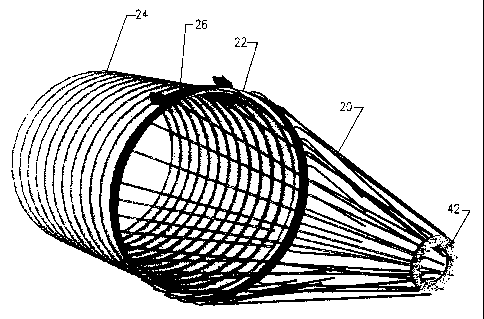
Reference is firstly made to FIGS. 1-3. The beaver control screen
20 according to the preferred embodiment has a conical shape and a length
'L' which is longer than its diameter 'D', such that the surface thereof is
much larger than the area defined by its diameter 'D'. When the beaver
control screen 20 is partly obstructed, as with leaves and similar floating
debris for examples, it still offers an opened surface which is substantially
similar or larger than the cross-section area of the culvert pipe. In the
beaver control screen 20 according to the preferred embodiment, the length
'L' of the conical portion is about 60 inches and the diameter 'D' is about
42 inches. The diameter 'E' of the small end of the conical portion is about
8
CA 02351181 2001-06-18
7 inches. The surface of the conical portion is about 5819 square inches
and the cross-section area of the culvert pipe having a diameter of about 42
inches is about 1385 square inches. Therefore the beaver control screen 20
can be obstructed over half of its surface and still offer an opened area
which is larger than the cross-section area of the culvert pipe.
A mounting ring 22 is made of flat bar material and defines the
large end, or the base of the beaver control screen 20. The ring 22 encloses
the end of the culvert pipe 24 on which the beaver control screen is
mounted. A hinge 26 is affixed to the upper segment of the culvert pipe 24
by fasteners, welds or otherwise and supports the conical portion of the
beaver control screen by means of gussets 28 affixed to the ring 22 and
pivoted to the hinge 26.
The conical portion of the beaver control screen 20 consists of an
outside conical layer 30, and an inside conical layer 32, mounted inside the
outside conical layer, and extending from the ring 22 over a distance 'F'
which is about one-half the length 'L' of the outside conical layer 30. On
the preferred beaver control screen, the surface of the outside conical layer
30 makes an angle 'G' of about 18-20 degrees with the longitudinal central
axis 34 of the beaver control screen 20. The surface of the inside conical
layer 32 makes an angle 'H' of about 22-24 degrees with the longitudinal
central axis 34. In FIG. 2, the longitudinal central axis 34 is shown inside
and outside the beaver control screen 20 for convenience, as the angles
described herein are geometrically identical with both positions of this axis.
In the preferred beaver control screen 20, the outside conical layer
30 is made of stiff and smooth rods 36, which are spaced apart a spacing
'J' of about 6-7 inches around the ring 22. The inside conical layer 32 is
9
CA 02351181 2001-06-18
also made of stiff and smooth rods 38 which are spaced apart around the
ring 22 the same distance 'J' . The rods 38 of the inside conical layer 32
are staggered between the rods 36 of the outside conical layer 30. The rods
38 of the inside conical layer 32 extends over a surface of about 2/3 of the
circumference of the outside conical layer 30 as indicated by the arrow 40
in FIG. 4. This surface 40 is designated as the submerged segment of the
beaver control screen 20. The purpose of this arrangement is to provide
more opened area over the top portion, or emerged segment of the beaver
control screen 20, to let a substantial quantity of floating debris, such as
leaves, twigs and straw to pass through the screen. This also provide better
space for fish passage. The submerged segment 40 of the screen 20 has
smaller openings to prevent adult and juvenile beavers from swimming
through the screen for the purpose of anchoring the foundation of a dam to
the end of the culvert pipe.
Referring now to FIGS. 5 and 6, some important features of the
beaver control screen 20 will be described. The apex of the outside conical
layer 30 comprises an annular plate 42 which has an outside diameter 'E'
of about 7 inches, and an inside diameter 'K' of about 4-1/2 inches, when
applied to the dimension set of the beaver control screen 20 according to
the preferred embodiment. In this preferred embodiment, there are between
about twenty two to twenty four rods 36 in the outer conical layer 30. For
the purpose of describing the following features, the number of rods 36 is
taken as being twenty two. These rods 36 are alternately affixed to the
annular plate 42 with one rod affixed to the outside edge 44 of the annular
plate 42 and the next rod affixed to the inside edge 46 of the annular plate
42. This arrangement provides a rod spacing 'M' between the rods along
the outside edge 44 of the annular plate 42 of about one inch, and a rod
spacing 'N' between adjacent rods of about 1-3/4 inches. It will be
CA 02351181 2001-06-18
appreciated that the adjacent rod spacing on the outside conical layer 30
varies from 1-3/4 inches at the apex 42 to about seven inches at the base
ring 22.
For reference purpose the adjacent rod spacing 'P' at the dimension
'F' between the apex 42 and the base ring 22 of the screen is about four
inches as illustrated in FIG. 6. The spacing 'Q' between a rod 36 from the
outside conical layer 30 and an adjacent rod 38 from the inside conical
layer 32 at the dimension 'F' is about 3-1/2 inches. From previously
mentioned dimensions, it will be appreciated that the spacing 'R' between
the same adjacent rods at the support ring 22 is also about 3-1/2 inches.
Consequently, the spacing between a rod 36 in the outside conical layer 30
and an adjacent rod 38 in the inside conical layer 32 is about 3-1/2 inches
along the entire length of the adjacent rod 38.
The rod diameter in the preferred beaver control screen 20 is about
~ one-half inch. Therefore, the clearance between any two adjacent rods at
the base of the beaver control screen 20 and over a distance of about one-
half the total length of the beaver control screen 20 is about three inches.
This clearance has been found to be ideal for preventing adult and juvenile
beavers from circulating through the screen near the end of the culvert pipe
24 where a beaver dam needs to the anchored. This clearance is also
advantageous for allowing common debris to float through the screen 20
without clogging the screen and to facilitate fish passage.
And of course, whenever some larger debris remain entangled to the
surface of the beaver control screen 20 the provision of the hinge 26 makes
it possible for someone standing on the end of the culvert pipe 24 to tilt the
beaver control screen 20 upward to release the debris and to clean the
11
CA 02351181 2001-06-18
screen.
Concerning the apex of the screen, it will also be appreciated that
the clearance 'S' between any adjacent rods in the outside conical layer 30
is at least about 1.25 inch or more. This dimension has also been found to
be advantageous for allowing local fish to easily swim through the beaver
control screen 20, whether the screen is installed on the upstream or
downstream end of the culvert pipe, without encountering any tight
convergence where the fish can get caught. The beaver control screen 20
according to the present invention is therefore more acceptable to habitat
conservation regulations than other cone-shaped screens of the prior art.
As to other dimensions, manner of usage and operation of the
present invention, the same should be apparent from the above description
and accompanying drawings, and accordingly further discussion relative to
the manner of making, using and operating the invention would be
1 S considered repetitious and is not provided.
While one embodiment of the present invention has been illustrated
and described herein above, it will be appreciated by those skilled in the art
that various modifications, alternate constructions and equivalents may be
employed without departing from the true spirit and scope of the invention.
For example, the beaver control screen can be made of different materials,
such as metal or plastic. It and can be made to mount on culvert pipes
made of corrugated steel, concrete, plastic or other material, and having a
circular or an oval shape. Therefore, the above description and the
illustrations should not be construed as limiting the scope of the invention
which is defined by the appended claims.
12