Sélection de la langue

Search

Sommaire du brevet 2353237 

Énoncé de désistement de responsabilité concernant l'information provenant de tiers

Une partie des informations de ce site Web a été fournie par des sources externes. Le gouvernement du Canada n'assume aucune responsabilité concernant la précision, l'actualité ou la fiabilité des informations fournies par les sources externes. Les utilisateurs qui désirent employer cette information devraient consulter directement la source des informations. Le contenu fourni par les sources externes n'est pas assujetti aux exigences sur les langues officielles, la protection des renseignements personnels et l'accessibilité.

Disponibilité de l'Abrégé et des Revendications

L'apparition de différences dans le texte et l'image des Revendications et de l'Abrégé dépend du moment auquel le document est publié. Les textes des Revendications et de l'Abrégé sont affichés :

  • lorsque la demande peut être examinée par le public;
  • lorsque le brevet est émis (délivrance).
(12) Demande de brevet: (11) CA 2353237
(54) Titre français: OUTIL D'EBARBAGE
(54) Titre anglais: DEBURRING TOOL
Statut: Réputée abandonnée et au-delà du délai pour le rétablissement - en attente de la réponse à l’avis de communication rejetée
Données bibliographiques
(51) Classification internationale des brevets (CIB):
  • B24B 09/04 (2006.01)
  • A63C 03/10 (2006.01)
(72) Inventeurs :
  • BENNINK, JOHANNES MARTINUS
  • DEBARTOLO, MARIO (Etats-Unis d'Amérique)
(73) Titulaires :
  • DUECENTO
(71) Demandeurs :
  • DUECENTO
(74) Agent: SMART & BIGGAR LP
(74) Co-agent:
(45) Délivré:
(22) Date de dépôt: 2001-07-18
(41) Mise à la disponibilité du public: 2002-01-19
Licence disponible: S.O.
Cédé au domaine public: S.O.
(25) Langue des documents déposés: Anglais

Traité de coopération en matière de brevets (PCT): Non

(30) Données de priorité de la demande:
Numéro de la demande Pays / territoire Date
1015739 (Pays-Bas (Royaume des)) 2000-07-19

Abrégés

Abrégé anglais


Deburring tools for removing a burr from a piece of sheet
metal like a skate iron. The deburring tool is provided
with two clamping jaws, between which an edge of the sheet
metal can be pulled. The clamping jaws are resiliently
mounted one to the other and at least one of the clamping
jaws consists of a cutter.

Revendications

Note : Les revendications sont présentées dans la langue officielle dans laquelle elles ont été soumises.


Claims
1. Deburring tool for removing a burr of a piece of sheet
metal, provided with at least one cutter which is
operationally moved alongside an edge of the piece of sheet
metal, characterized in that the deburring tool comprises a
clamp, provided with two clamping jaws, of which at least
one clamping jaw is the cutter.
2. Deburring tool according to claim 1, characterized in
that spring means are provided, for clamping the two jaws
together with a predefined force.
3. Deburring tool according to claim 2, characterized in
that the spring means consist of two stacked sheets made of
a resilient material, like plastic, which are connected on
a first edge one to the other and on which the clamping
jaws are mounted on a second edge, opposite to the first
edge.
4. Deburring tool according to claim 3, characterized in
that the cutter comprises a plate made of a hard material,
like steel or ceramic, mounted near the second edge.
5. Deburring tool according to claim 2, characterized in
that the clamp consists of a mounting plate, on an edge of
which two cutters are mounted, facing each other.
6. Deburring tool according to claim 5, characterized in
that each cutter comprises a plate made of a hard material,
like steel or ceramic.
7. Deburring tool according to claim 5 of 6,
characterized in that the mounting plate and each cutter
are provided with a mounting hole, through which a mounting

8
pin is fed, and that the spring means consist of two spring
washers, mounted on both side of the cutters.
8. Deburring tool according to claim 7, characterized in
that the mounting plate has at least substantially the same
thickness as the sheet metal.
9. Deburring tool according to claim 8, characterized in
that the mounting plate consists of a bottom of two
recesses, made on both sides of a thicker guiding plate and
that the guiding plate is provided wit a channel, through
which the sheet metal can be fed.
10. Deburring tool according to claim 4 or 6,
characterized in that the cutter is rotatable mounted.

Description

Note : Les descriptions sont présentées dans la langue officielle dans laquelle elles ont été soumises.

CA 02353237 2001-08-16
1
Debarring tool
The invention relates to a debarring tool for removing a
burr of a piece of sheet metal, provided with at least one
cutter, which is operationally moved alongside an edge of
the piece of sheet metal. Arrangements of this type,
normally shaped as a hand tool, are well known in the art.
The problem with these known debarring tools is that they
don't give a reproducible result and that they often damage
the piece of sheet metal.
The present invention enables even an unskilled person to
deburr a piece of sheet metal and in particular a skate
iron. For skate irons often a small grinding stone is used
for removing a burr, for example after the skates have been
ground, but this is time consuming and tricky. The
inventive tool is characterized in that the debarring tool
comprises a clamp, provided with two clamping jaws, of
which at least one clamping jaw is the cutter. It is
sufficient then to pull for example a skate iron between
the clamping jaws in a single continuous movement in order
to deburr at least one side of it.
A favourable embodiment of the debarring tool, which makes
it even more convenient debarring a plate, is characterized
in that spring means are provided, for clamping the two
jaws together with a predefined force.
An embodiment of the inventive debarring tool which can be
manufactured cheap, is characterized in that the spring
means consist of two stacked sheets made of a resilient
material, like plastic, which are connected on a first edge
one to the other and on which the clamping jaws are mounted
on a second edge, opposite to the first edge.

CA 02353237 2001-08-16
2
A very flat embodiment of the invention, which can be
stored conveniently, is characterized in that the cutter
comprises a plate made of a hard material, like steel or
ceramic, mounted near the second edge.
An alternative embodiment of the inventive deburring tool,
with which two sides of the piece of sheet metal can be
deburred simultaneously, is characterized in that the clamp
consists of a mounting plate, on an edge of which two
cutters are mounted, facing each other.
A favourable embodiment in which the spring means have been
realised simple and effective, is characterized in that the
mounting plate and each cutter are provided with a mounting
hole, through which a mounting pin is fed, and that the
spring means consist of two spring washers, mounted on both
sides of the cutters. The mounting pin may consist here for
example of a screwed or riveted connection.
Another favourable embodiment, which gives the best results
for sheet metal with a given thickness, is characterized in
that the mounting plate has at least substantially the same
thickness as the sheet metal.
Another favourable embodiment of the inventive deburring
tool, which guarantees a very good guidance of the sheet
metal plate, is characterized in that the mounting plate
consists of a bottom of two recesses, made on both sides of
a thicker guiding plate and that the guiding plate is
provided wit a channel, through which the sheet metal can
be fed. The guiding plate can be made in one single piece,
for example as an injection-moulded part, for example made
of plastic.

CA 02353237 2001-08-16
3
Another favourable embodiment of the inventive deburring
tool is characterized in that the cutter is rotatable
mounted, such that it can be rotated if the cutter has
locally become blunt.
The invention will now be further explained with a
reference to the figures, in which:
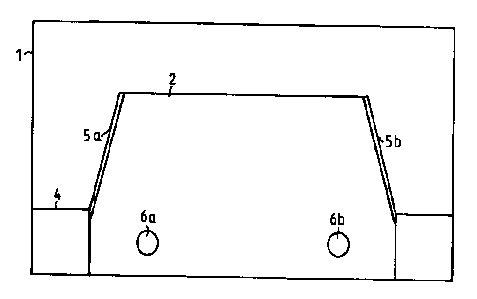
Fig. 1A represents in side view first possible
a
embodiment of a deburring tool according to the
invention;
Fig. 1B represents this embodimentin front view;
Fig. 2A represents in side view second possible
a
embodiment of a deburring tool according to the
invention;
Fig. ~2B represents this embodimentin front view;
Fig. 3A represents in side view third possible
a
embodiment of a deburring tool according to the
invention;
Fig. 3B represents this embodimentin front view;
Fig. 4A represents in front view possible embodiment
a of
a two-sided deburring tool ;
Fig. 4 Brepresents this embodiment
in cross section.
Fig. 1A represents in side view a first possible embodiment
of a deburring tool according to the invention, provided
with a first clamping jaw 1 and a second clamping jaw 2,
between which a plate 3 can be pulled which has to be
deburred. Jaw 1 and jaw 2 are separated by a spacer 4 in
such a manner that plate 3 neatly fits between clamps 1,2.
Jaw 1 may be given a slight bending, in which case plate 3
is pushed actively against jaw 2. At least one side of jaw
2 is provided with a sharp edge 5 that will remove a blurr
from plate 3, if present, when it is pulled through. Jaw 1,

CA 02353237 2001-08-16
4
spacer 4 and jaw 2 are kept together by rivets or screwed
joints 6.
Fig. 1B represents this embodiment in front view, with jaw
1, jaw 2 having sharp edges 5a,5b, spacer 4 and two rivets
6a, 6b .
Fig. 2A represents in side view a second possible
embodiment of a debarring tool according to the invention,
provided with a plate-shaped first clamping jaw 7 and a
second clamping jaw 8 that has been mounted to a plate 9.
First clamping jaw 7 and plate 9 together are clamped in a
U-shaped profile 10 and fixed with two rivets or screwed
joints 11. They may be made of a resilient material, like
metal or plastic. In order to remove a burr from a plate
12, the plate can be pulled between first clamping jaw 7
and second clamping jaw 8, in the process of which a sharp
edge 13 cuts off a burr that might be present. In this
embodiment, second clamping jaw 8 is a circular plate made
of tool steel or a ceramic material, which is mounted to
plate 9 with the aid of a screw 14. An advantage is that
the plate can be rotated if one part of sharp edge 13 has
become blunt. Another advantage of the embodiment shown
here is also that plates with different or uneven thickness
can be debarred, because of the resilient behaviour of
first clamping jaw 7 and/or plate 9.
Fig. 2B represents this embodiment in front view, with
first clamping jaw 7, plate 9, U-shaped profile 10, rivets
11a, 11b and second clamping jaw 8 which is mounted to
plate 9 with the aid of screw 14.
Fig. 3A represents in side view a third possible embodiment
of a debarring tool according to the invention, with a
plate-shaped first clamping jaw 15 and a second clamping

CA 02353237 2001-08-16
jaw 16 that has been mounted to a plate 17. In this
embodiment, first clamping jaw 15 is provided with a
projecting part, which in a state of rest at least
substantially contacts second clamping jaw 16. First
5 clamping jaw 15 and plate 17 together are clamped in a U-
shaped profile 18 and fixed with two rivets or screwed
joints 19. They may be made of a resilient material, like
metal or plastic. In order to remove a burr from a plate
20, the plate can be pulled between first clamping jaw 15
and second clamping jaw 21, in the process of which a sharp
edge 21 cuts off a burr that might be present. In this
embodiment, second clamping jaw 16 is a rectangular plate
made of tool steel or a ceramic material, which is mounted
to plate 17 with the aid of a screw 22. An advantage is
that sharp edge 21 always makes a near optimal cutting
angle, while the plate may be rotated over ninety degrees
if sharp edge 21 has become blunt. An additional advantage
of the embodiment shown here is that even very thin plates
with different or uneven thicknesses can be deburred,
because of the resilient behaviour of first clamping jaw 15
and/or plate 17 and the upright part of first clamping jaw
15.
Fig. 3B represents this embodiment in front view, with
first clamping jaw 15, plate 17, U-shaped profile 18,
rivets l9a,l9b and second clamping jaw 16 which is mounted
to plate 17 with the aid of screw 22. The embodiment shown
here is particularly well suited for removing a burr from a
skate iron, for example when the skate has been ground,
simply by pulling it a few times through the deburring
tool.
Fig. 4A represents in front view a possible embodiment of a
two-sided deburring tool, consisting of a guiding plate 23
in which recesses 24a,24b have been made on both sides, in

CA 02353237 2001-08-16
6
which two plates 25a,25b made of tool steel or a ceramic
material are placed, between which the sheet metal to be
deburred can be pulled. The thickness of the wall between
the recesses 24a,24b is chosen to be the same as the
thickness of the sheet metal that has to be deburred and it
forms a mounting plate for the plates 25a,25b. In order to
let pass the sheet metal, a channel 26 is made in a
longitudinal direction in guiding plate 23, having a width,
which corresponds with the thickness of the sheet metal.
Plates 25a,25b are mounted to the wall between the recesses
24a,24b with the aid of a rivet 27. In order to provide
some resilience, spring washers 28a,28b have been placed
between the heads of rivet 21 and plates 25a,25b.
Fig. 4B represents this embodiment in cross section,
guiding plate 23, in which recesses 24a,24b are made, in
which two plated 25a,25b made of tool steel or a ceramic
material are placed, between which the sheet metal to be
deburred may be pulled. The unit is kept together with a
rivet 27, while spring washers 28a,28b provide for some
resilience.

Dessin représentatif
Une figure unique qui représente un dessin illustrant l'invention.
États administratifs

2024-08-01 : Dans le cadre de la transition vers les Brevets de nouvelle génération (BNG), la base de données sur les brevets canadiens (BDBC) contient désormais un Historique d'événement plus détaillé, qui reproduit le Journal des événements de notre nouvelle solution interne.

Veuillez noter que les événements débutant par « Inactive : » se réfèrent à des événements qui ne sont plus utilisés dans notre nouvelle solution interne.

Pour une meilleure compréhension de l'état de la demande ou brevet qui figure sur cette page, la rubrique Mise en garde , et les descriptions de Brevet , Historique d'événement , Taxes périodiques et Historique des paiements devraient être consultées.

Historique d'événement

Description Date
Inactive : CIB de MCD 2006-03-12
Demande non rétablie avant l'échéance 2005-07-18
Le délai pour l'annulation est expiré 2005-07-18
Réputée abandonnée - omission de répondre à un avis sur les taxes pour le maintien en état 2004-07-19
Inactive : Grandeur de l'entité changée 2003-05-14
Demande publiée (accessible au public) 2002-01-19
Inactive : Page couverture publiée 2002-01-18
Lettre envoyée 2001-10-16
Inactive : CIB en 1re position 2001-09-19
Inactive : Correspondance - Formalités 2001-09-14
Inactive : Correspondance - Transfert 2001-09-14
Inactive : Transfert individuel 2001-08-16
Modification reçue - modification volontaire 2001-08-16
Inactive : Correspondance - Formalités 2001-08-16
Inactive : Certificat de dépôt - Sans RE (Anglais) 2001-08-14
Demande reçue - nationale ordinaire 2001-08-08

Historique d'abandonnement

Date d'abandonnement Raison Date de rétablissement
2004-07-19

Taxes périodiques

Le dernier paiement a été reçu le 2003-04-25

Avis : Si le paiement en totalité n'a pas été reçu au plus tard à la date indiquée, une taxe supplémentaire peut être imposée, soit une des taxes suivantes :

  • taxe de rétablissement ;
  • taxe pour paiement en souffrance ; ou
  • taxe additionnelle pour le renversement d'une péremption réputée.

Les taxes sur les brevets sont ajustées au 1er janvier de chaque année. Les montants ci-dessus sont les montants actuels s'ils sont reçus au plus tard le 31 décembre de l'année en cours.
Veuillez vous référer à la page web des taxes sur les brevets de l'OPIC pour voir tous les montants actuels des taxes.

Historique des taxes

Type de taxes Anniversaire Échéance Date payée
Taxe pour le dépôt - petite 2001-07-18
Enregistrement d'un document 2001-08-16
TM (demande, 2e anniv.) - générale 02 2003-07-18 2003-04-25
Titulaires au dossier

Les titulaires actuels et antérieures au dossier sont affichés en ordre alphabétique.

Titulaires actuels au dossier
DUECENTO
Titulaires antérieures au dossier
JOHANNES MARTINUS BENNINK
MARIO DEBARTOLO
Les propriétaires antérieurs qui ne figurent pas dans la liste des « Propriétaires au dossier » apparaîtront dans d'autres documents au dossier.
Documents

Pour visionner les fichiers sélectionnés, entrer le code reCAPTCHA :


Pour visualiser une image, cliquer sur un lien dans la colonne description du document. Pour télécharger l'image (les images), cliquer l'une ou plusieurs cases à cocher dans la première colonne et ensuite cliquer sur le bouton "Télécharger sélection en format PDF (archive Zip)" ou le bouton "Télécharger sélection (en un fichier PDF fusionné)".

Liste des documents de brevet publiés et non publiés sur la BDBC .

Si vous avez des difficultés à accéder au contenu, veuillez communiquer avec le Centre de services à la clientèle au 1-866-997-1936, ou envoyer un courriel au Centre de service à la clientèle de l'OPIC.


Description du
Document 
Date
(aaaa-mm-jj) 
Nombre de pages   Taille de l'image (Ko) 
Dessin représentatif 2001-12-23 1 4
Description 2001-07-17 6 262
Abrégé 2001-07-17 1 13
Dessins 2001-07-17 4 63
Revendications 2001-07-17 2 63
Description 2001-08-15 6 236
Abrégé 2001-08-15 1 10
Revendications 2001-08-15 2 53
Courtoisie - Certificat d'enregistrement (document(s) connexe(s)) 2001-10-15 1 136
Certificat de dépôt (anglais) 2001-08-13 1 175
Rappel de taxe de maintien due 2003-03-18 1 106
Courtoisie - Lettre d'abandon (taxe de maintien en état) 2004-09-12 1 178
Correspondance 2001-08-16 1 28
Correspondance 2001-08-15 10 344
Correspondance 2001-09-13 1 39