Sélection de la langue

Search

Sommaire du brevet 2356315 

Énoncé de désistement de responsabilité concernant l'information provenant de tiers

Une partie des informations de ce site Web a été fournie par des sources externes. Le gouvernement du Canada n'assume aucune responsabilité concernant la précision, l'actualité ou la fiabilité des informations fournies par les sources externes. Les utilisateurs qui désirent employer cette information devraient consulter directement la source des informations. Le contenu fourni par les sources externes n'est pas assujetti aux exigences sur les langues officielles, la protection des renseignements personnels et l'accessibilité.

Disponibilité de l'Abrégé et des Revendications

L'apparition de différences dans le texte et l'image des Revendications et de l'Abrégé dépend du moment auquel le document est publié. Les textes des Revendications et de l'Abrégé sont affichés :

  • lorsque la demande peut être examinée par le public;
  • lorsque le brevet est émis (délivrance).
(12) Brevet: (11) CA 2356315
(54) Titre français: MACHINE SYNCHRONE
(54) Titre anglais: SYNCHRONISATION SYSTEM
Statut: Durée expirée - au-delà du délai suivant l'octroi
Données bibliographiques
(51) Classification internationale des brevets (CIB):
  • H02K 03/28 (2006.01)
  • H02K 01/18 (2006.01)
  • H02K 01/24 (2006.01)
  • H02K 07/12 (2006.01)
  • H02K 07/18 (2006.01)
(72) Inventeurs :
  • WOBBEN, ALOYS (Allemagne)
(73) Titulaires :
  • ALOYS WOBBEN
(71) Demandeurs :
  • ALOYS WOBBEN (Allemagne)
(74) Agent: OYEN WIGGS GREEN & MUTALA LLP
(74) Co-agent:
(45) Délivré: 2003-11-18
(86) Date de dépôt PCT: 2000-03-03
(87) Mise à la disponibilité du public: 2000-12-07
Requête d'examen: 2001-06-20
Licence disponible: S.O.
Cédé au domaine public: S.O.
(25) Langue des documents déposés: Anglais

Traité de coopération en matière de brevets (PCT): Oui
(86) Numéro de la demande PCT: PCT/EP2000/001882
(87) Numéro de publication internationale PCT: EP2000001882
(85) Entrée nationale: 2001-06-20

(30) Données de priorité de la demande:
Numéro de la demande Pays / territoire Date
199 23 925.8 (Allemagne) 1999-05-26

Abrégés

Abrégé français

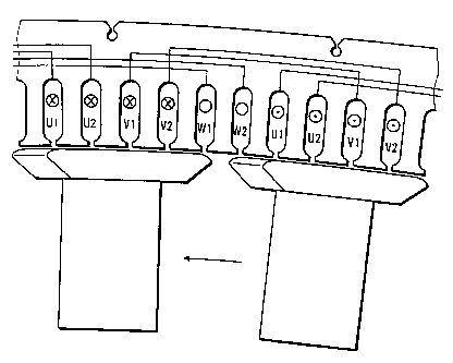
Les machines synchrones sont connues depuis longtemps sous diverses formes. De telles machines produisent, en mode générateur ou en mode moteur, en cas de court-circuit, par exemple un court-circuit aux bornes d'alimentation ou à l'intérieur de la bobine du stator, des couples de court-circuit très importants. Ces pics de couples de court-circuit peuvent alors atteindre des valeurs allant jusqu'à six à huit fois le couple nominal de la machine synchrone. Lors de la construction mécanique de la machine synchrone, un calcul concernant le cas très rare de court-circuit et l'apparition d'un couple de court-circuit très important qui en résulte doit également être réalisé. L'objectif de la présente invention est de simplifier la construction d'une telle machine synchrone et d'éviter les inconvénients mentionnés précédemment. La présente invention concerne une machine synchrone pourvue d'un rotor et d'un stator, ledit stator présentant au moins deux bobines à courant alternatif (triphasé) indépendantes, isolées électriquement et/ou spatialement l'une de l'autre.


Abrégé anglais


Synchronous machines have long been known in many different
forms. In operation as a generator and also in operation as a motor, in
the situation of a short-circuit, for example a short-circuit at connecting
terminals or also within the stator winding, such synchronous machines
produce very high short-circuit torques. In that respect, those very high
short-circuit torque peaks can reach values of up to six to eight times the
rated torque of the synchronous machine. Therefore, consideration must
also be given to the very rare short-circuit situation and the concomitant
occurrence of a very high short-circuit torque, in regard to the mechanical
construction of the synchronous machine.
The object of the invention is to simplify the synchronous machine
in regard to its structure and to avoid the above-mentioned
disadvantages.
A synchronous machine having a rotor and a stator, wherein the
stator has at least two independent alternating (three-phase) current
windings which are electrically and/or spatially isolated from each other.

Revendications

Note : Les revendications sont présentées dans la langue officielle dans laquelle elles ont été soumises.


8~
WHAT IS CLAIMED IS:
1. A wind power installation comprising a synchronous machine having a rotor
and a
stator, wherein the stator has at least two independent three-phase systems
which are
electrically isolated from each other, wherein the synchronous machine has
means
which always limit a short-circuit torque which occurs in the case of a short-
circuit at
a stator winding to a maximum of four times a rated torque.
2. A wind power installation according to claim 1 wherein the means limits the
short-circuit torque to be always less than double the rated torque.
3. A wind power installation according to any one of claims 1 or 2 wherein the
rotor has
pole shoes of a substantially arrow-shaped configuration.
4. A wind power installation according to any one of claims 1 to 3 wherein the
rotor and
the stator are carried by a common axle journal and the stator is mounted by a
flange
mounting directly to the axle journal.
5. A wind power installation according to any one of claims 1 to 4 wherein the
stator is
held by a carer, the rotor of the synchronous machine and the carrier are
carried by a
stationary axle journal, and the carrier and the axle journal. are in the form
of a
structural unit.
6. A wind power installation according to claim 5 wherein the synchronous
machine is a
synchronous generator, and the carrier and the axis journal are in the form of
an
integral cast steel component.

9
7. A wind power installation according to any one of claims 1 to 6 wherein a
first one of
the three-phase systems is displaced through an (electrical) angle of about 30
degrees
relative to a second one of the three-phase systems.
8. A wind power installation according to any one of claims 1 to 7 with a
power of at
least 100 kW.

Description

Note : Les descriptions sont présentées dans la langue officielle dans laquelle elles ont été soumises.


CA 02356315 2001-06-20
c
r
Synchronous machine
Synchronous machines have long been known in many different
forms. In operation as a generator and also in operation as a motor, in
the situation of a short-circuit, for example a short-circuit at connecting
terminals or also within the stator winding, such synchronous machines
produce very high short-circuit torques. In that respect, those very high
short-circuit torque peaks can reach values of up to six to eight times the
rated torque of the synchronous machine. Therefore, consideration must
also be given to the very rare short-circuit situation and the concomitant
occurrence of a very high short-circuit torque, in regard to the mechanical
construction of the synchronous machine.
Synchronous machines of the above-described kind have already
long been used in wind power installations from the company Enercon. In
those types of wind power installations, the synchronous machines are in
the form of ring generators, wherein the generator rotor rotates within the
generator stator and the generator rotor is mounted by a flange mounting
directly to the rotor of the wind power installation. In the case of a
generator rotor which is directly mounted by a flange mounting to a drive

CA 02356315 2001-06-20
2
machine, very high short-circuit torques occur in a short-circuit situation
and the constructions are linked to very high cost levels and a very high
level of maintenance, in order to avoid major damage.
Therefore, in a synchronous machine as is used for example in the
wind power installation of type E-40 from Enercon, a mechanical safety
device in the form of a shearing pin coupling was developed and used
therein. In that case the so-called stator carrier star or spider (carrier)
which carries the stator (stationary member of the generator) is
connected by way of shearing pins to the axle journal or stub axle which is
also stationary. In the event of a generator short-circuit, the pins shear
and permit the stator also to rotate about the axle journal. In that way
the transmitted torque is limited to a maximum of four times the rated
torque and the drive train is guaranteed to be safeguarded in a generator
short-circuit situation.
DE 197 29 034 discloses a wind power installation with a
synchronous generator which has a generator stator with a stator winding
and a generator rotor which is movable relative to the stator. In one
embodiment the stator there has a 6-phase stator winding. The 6 phases
of the synchronous generator are connected to a common rectifier circuit.
2o WO 88/07782 discloses a wind power installation with an electrical
generator having a rotor and a stator. The stator there has a plurality of
turns which can be connected together in different ways by suitable
switching means in order to produce a desired output signal.
DE 40 32 492 discloses an electrical machine for power converter
operation comprising a multi-phase stator winding which can be switched
over, that can also be used in a wind power installation. The stator
winding in that case is subdivided into similar, respectively m-phase
winding subsystems which are galvanically separated and fixedly
connected in a star or polygon configuration. Special switching elements
3o are provided for switching over the winding.
AMENDED PAGE

CA 02356315 2001-06-20
3
The object of the invention is to simplify the synchronous machine
in regard to its structure and to avoid the above-mentioned
disadvantages.
In accordance with the invention that object is attained by a
synchronous machine having the feature set forth in claim 1.
Advantageous developments are described in the further claims.
The invention is based on the realisation that particular safety
elements such for example a shearing pin coupling are not necessary if
the maximum short-circuit torque is limited to a fraction of that which is
1o hitherto usual. Preferably, in the synchronous machine according to the
invention, the short-circuit torque is always less than double the torque.
For limiting the short-circuit torque the rotor has at least two
independent three-phase windings which are electrically and/or spatially
isolated from each other. That provides that the power of the generator is
divided to two different three-phase systems. With two independent
three-phase systems, each system involves only 50% of the rated power.
Those systems are displaced through an angle of 30°. This means
that
both three-phase systems are electrically and mechanically (spatially)
isolated. In that way however the reactance Xd is also approximately
2o doubled and thus the short-circuit current is halved. This affords the
particular advantage that, in the event of a short-circuit in a system, only
half the short-circuit power can occur. It is thus possible to have a
reduction in the maximum short-circuit moment (short-circuiting of two
phases, for example U1 and V1) by 50% relative to the hitherto usual
Z5 single-system arrangement.
Another measure for reducing the short-circuit torque is to
eliminate a 'damper cage, especially as the reactances Xd" and Xd'
determine the dynamic short-circuit current configuration. The maximum
short-circuit torque can be reduced by about 30% by virtue of the
3o omission of the damper cage, that is to say by virtue of the use of a
salient-pole machine without damper winding.
AMENDED PAGE

CA 02356315 2001-06-20
4
As a further measure for reducing the torque involved, it is
proposed that the pole heads of the rotor are of an approximately arrow-
shaped configuration. In the case of a short-circuit in one of the two
three-phase systems the magnetic flux in the exciter pole can then very
rapidly deflect in the direction of rotation. That affords soft dynamic
decoupling of the exciter flux with the stator flux within a groove. Per pole
width, the short-circuit current then flows only in two of a total of six
grooves. That dynamic decoupling of the exciter flux still further reduces
the short-circuit torque.
The invention will be described in greater detail hereinafter by
means of an embodiment illustrated in the drawings in which:
Figure 1 is a view in cross-section through a wind power installation
pod according to the invention, with a synchronous generator according to
the invention,
i5 Figure 2 is a view in cross-section through a known wind power
installation pod with a known synchronous generator,
AMENDED PAGE

CA 02356315 2002-03-13
4a
Figure 3a is a view of part of a synchronous generator according to
the invention,
Figure '3b is a diagrammatic view of the phase conductor distribu-
tion,
Figure 3c shows a view of part of a known synchronous generator,
Figure 4a Is a perspective view of an arrow-shaped pole head,
Figure 4b is a plan view of an arrow-shaped pole head,
Figure S shows a magnetic flux configuration without short-circuit,
Figure 6 shows a magnetic flux configuration with short-circuit, and
1o Figures 7 and 8 show measurement recordings in a short-circuit
situation with partial load or full load.
Figure Z shows a part of a wind power installation pod with a rotor 1
which is supported on an axle journal 2 or stub axle. The rotor 1 is con-
nected without a transmission directly to a generator rotor of a synchro-
nous generator. The rotor generator is disposed within a generator stator
3 which Is mounted by a flange mounting d(rectly to the axle journal 2.The
axle journal Z, like the entire drive train mounted thereon, besides the
generator, is carried by the machine carrier 4. Also shown are a rotor hub
S and a bearing 6.
Zo Figure 2 shows a wind power installation pod with a known syn-
chronous generator, in which the generator stator 3 is carried by a stator
carrier star 7 or spider and the stator carrier star 7 is in turn disposed on
the axle journal 2 and is held fast by means of a shearing pin coupling 8.
In the case of a short-circuit, for example at the connecting termi
z5 pals or also within the stator winding (not shown), very high short-circuit
torques are produced in the synchronous generator. These very high
torque peaks which can retch values of up to six to eight times (or more)
the rated torque have to be taken irito consideration by means of the me
chanical structure involved. In the case of the wind power installation of
3o type E-40 from Enercon as shown in Figure 2, that mechanical structure is
embodied by a mechanical safety device in the

CA 02356315 2001-06-20
' S
form of the shearing pin coupling. In the case of a generator short-circuit,
the pins shear and permit the stator also to rotate about the axle journal.
That provides that the transmitted torque is limited to a maximum of four
times the rated torque. Therefore, in the event of a generator short
s circuit, the drive train is guaranteed to be safeguarded.
Figure 3a is a view in cross-section of a part of a synchronous
machine (synchronous generator) according to the invention. In this case
the rotor rotates within the stator and the rotor salient-pole machine does
not have a damper cage (damper winding} or a short-circuit ring.
1o In addition two independent three-phase windings U1, V1, W1 and
U2, V2, W2 are disposed in the stator. The power of the generator is thus
divided to the two three-phase windings (three-phase systems) so that
each three-phase system has to deal with only 50% of the rated power.
The two three-phase systems are displaced through an electrical angle of
15 30% and are thus electrically and mechanically (spatially) isolated from
each other. That means however that the reactance Xd is also
approximately doubled and thus the short-circuit current is halved. That
has the advantage that, in the case of a short-circuit in a three-phase
system, only half the short-circuit power can occur. That permits a
20 reduction in the maximum short-circuit moment (short-circuit of two
phases, for example U1 and V1), by 50% relative to a system
arrangement (state of the art). Figure 3b is a better overview showing
the arrangement of the individual phases of the two different three-phase
systems over a larger region of the stator.
25 Figure 3c is a view in cross-section of part of a known synchronous
generator (synchronous machine in the form of a full-pole machine with
damper cage) (type E-40) in which the generator rotor is equipped with a
damper cage and the power of the generator is taken up by only one
three-phase system U, V, W. Shown are: pole core 9, short-circuit ring
3o 10, damper bars 1i, stator plate 12.

CA 02356315 2001-06-20
6
The pole shoes or pole heads which are carried on the pole cores of
the rotor - as shown in Figure 3a - are of an arrow-shaped configuration,
as shown in Fgure 4.
In this case, the pole head - see Figure 4b - in a plan view onto the
surface which is towards the air gap, is in the shape of an arrow. The
edge which is the front edge in the direction of movement of the rotor, as
'identified by an arrow in Figure 3a, has twb edge portions which are
arranged in angled relationship with each other and which come together
to form a point and which are arranged inclinedly with respect to the
1o direction of movement of the rotor and thus the pole heads. The edge
portions are arranged at an angle of about 150° with respect to the
direction of movement of the rotor. The edge of a pole head, which is the
trailing edge in the direction of movement of the rotor, also has edge
portions which are arranged inclinedly with respect to the direction of
movement of the rotor.
Figure 5 shows a view of the magnetic flux in the generator
according to the invention (rotor--> stator) without short-circuit. In this
case the magnetic flux passes directly from the pole head to the stator
uniformly between the grooves.
In the event of a short-circuit - Figure 6 - in a groove - identified
here by U2 - the magnetic field lines (magnetic flux ~) must deflect. The
arrow shape of the pole heads permits deflection within the pole towards
the right and towards the left so that the magnetic flux can be distributed
to other adjacent groove lands. The deflection of the magnetic flux in the
exciter pole in the direction of rotation affords soft dynamic decoupling of
the exciter flux with the stator flux within a groove. Per pole width, the
short-circuit current flows only in two of a total of six grooves. This
dynamic decoupling of the exciter flux still further reduces the short-circuit
torque.
Figures 7 and 8 show series of time measurements by way of
example in respect of rotor torque, power and speed of rotation of a 1.5

CA 02356315 2001-06-20
MW synchronous generator (type E-66 from Enercon) under partial load
(1200 kW) and full load (1500 kW) and with an artificially produced
generator short-circuit. The measurements shows that the maximum
torque which occurs in all operating states due to a two-phase generator
short-circuit is markedly lower than double the rated torque.
As described the combination of various measures - at least two
independent three-phase' systems, no damper cage, arrow-shaped pole
heads - provides the drastic reduction in short-circuit moment, which is of
great advantage in particular in the case of a generator for use in wind
power installations. In conjunction with the reduction in short-circuit
moment, it is also possible to achieve a simplified machine design because
the overall stator carrier structure - Figure 1 - can be simplified
considerably in comparison with previous design configurations - Figure 2.

Dessin représentatif
Une figure unique qui représente un dessin illustrant l'invention.
États administratifs

2024-08-01 : Dans le cadre de la transition vers les Brevets de nouvelle génération (BNG), la base de données sur les brevets canadiens (BDBC) contient désormais un Historique d'événement plus détaillé, qui reproduit le Journal des événements de notre nouvelle solution interne.

Veuillez noter que les événements débutant par « Inactive : » se réfèrent à des événements qui ne sont plus utilisés dans notre nouvelle solution interne.

Pour une meilleure compréhension de l'état de la demande ou brevet qui figure sur cette page, la rubrique Mise en garde , et les descriptions de Brevet , Historique d'événement , Taxes périodiques et Historique des paiements devraient être consultées.

Historique d'événement

Description Date
Inactive : Périmé (brevet - nouvelle loi) 2020-03-03
Représentant commun nommé 2019-10-30
Requête visant le maintien en état reçue 2017-02-20
Inactive : CIB expirée 2016-01-01
Inactive : CIB de MCD 2006-03-12
Accordé par délivrance 2003-11-18
Inactive : Page couverture publiée 2003-11-17
Préoctroi 2003-08-27
Inactive : Taxe finale reçue 2003-08-27
Un avis d'acceptation est envoyé 2003-07-30
Lettre envoyée 2003-07-30
Un avis d'acceptation est envoyé 2003-07-30
Inactive : Approuvée aux fins d'acceptation (AFA) 2003-07-14
Modification reçue - modification volontaire 2003-05-05
Inactive : Dem. de l'examinateur par.30(2) Règles 2002-11-05
Lettre envoyée 2002-10-31
Avancement de l'examen jugé conforme - alinéa 84(1)a) des Règles sur les brevets 2002-10-31
Inactive : Avancement d'examen (OS) 2002-10-16
Inactive : Taxe de devanc. d'examen (OS) traitée 2002-10-16
Modification reçue - modification volontaire 2002-03-13
Inactive : Page couverture publiée 2001-12-13
Inactive : CIB en 1re position 2001-12-10
Inactive : Inventeur supprimé 2001-09-18
Inactive : Acc. récept. de l'entrée phase nat. - RE 2001-09-18
Demande reçue - PCT 2001-09-17
Toutes les exigences pour l'examen - jugée conforme 2001-06-20
Exigences pour une requête d'examen - jugée conforme 2001-06-20
Demande publiée (accessible au public) 2000-12-07

Historique d'abandonnement

Il n'y a pas d'historique d'abandonnement

Taxes périodiques

Le dernier paiement a été reçu le 2003-01-10

Avis : Si le paiement en totalité n'a pas été reçu au plus tard à la date indiquée, une taxe supplémentaire peut être imposée, soit une des taxes suivantes :

  • taxe de rétablissement ;
  • taxe pour paiement en souffrance ; ou
  • taxe additionnelle pour le renversement d'une péremption réputée.

Les taxes sur les brevets sont ajustées au 1er janvier de chaque année. Les montants ci-dessus sont les montants actuels s'ils sont reçus au plus tard le 31 décembre de l'année en cours.
Veuillez vous référer à la page web des taxes sur les brevets de l'OPIC pour voir tous les montants actuels des taxes.

Titulaires au dossier

Les titulaires actuels et antérieures au dossier sont affichés en ordre alphabétique.

Titulaires actuels au dossier
ALOYS WOBBEN
Titulaires antérieures au dossier
S.O.
Les propriétaires antérieurs qui ne figurent pas dans la liste des « Propriétaires au dossier » apparaîtront dans d'autres documents au dossier.
Documents

Pour visionner les fichiers sélectionnés, entrer le code reCAPTCHA :


Pour visualiser une image, cliquer sur un lien dans la colonne description du document. Pour télécharger l'image (les images), cliquer l'une ou plusieurs cases à cocher dans la première colonne et ensuite cliquer sur le bouton "Télécharger sélection en format PDF (archive Zip)" ou le bouton "Télécharger sélection (en un fichier PDF fusionné)".

Liste des documents de brevet publiés et non publiés sur la BDBC .

Si vous avez des difficultés à accéder au contenu, veuillez communiquer avec le Centre de services à la clientèle au 1-866-997-1936, ou envoyer un courriel au Centre de service à la clientèle de l'OPIC.


Description du
Document 
Date
(aaaa-mm-jj) 
Nombre de pages   Taille de l'image (Ko) 
Dessin représentatif 2001-10-18 1 9
Dessins 2003-05-04 11 212
Revendications 2003-05-04 2 59
Dessin représentatif 2003-10-15 1 10
Abrégé 2003-10-15 1 26
Description 2001-06-19 8 323
Abrégé 2001-06-19 1 26
Revendications 2001-06-19 2 58
Dessins 2001-06-19 11 196
Description 2002-03-12 8 322
Avis d'entree dans la phase nationale 2001-09-17 1 235
Avis du commissaire - Demande jugée acceptable 2003-07-29 1 160
PCT 2001-06-19 10 383
PCT 2001-06-20 5 167
Correspondance 2003-08-26 1 31