Note : Les descriptions sont présentées dans la langue officielle dans laquelle elles ont été soumises.
CA 02366221 2001-12-28
SYSTEM AND APPARATUS FOR
RAPIDLY INSTALLED BREAKWATER
BACKGROUND OF THE INVENTION
The present invention relates generally to floating breakwaters, and more
particularly, to floating breakwater systems capable of rapid deployment and
retrieval, and capable of breaking or attenuating wave action in open water.
In this
application, "open water" is used to denote any open water including ocean
water,
lake water, river water, dam water, and the like.
Breakwaters are typically either bottom-mounted or floating. Bottom-
mounted structures are generally composed of large rocks ("rip-rap") or
concrete,
and are massive permanent structures. Floating breakwaters have been used for
some time as non-permanent structures at harbor entrances, swimming beaches,
offshore construction, or for military operations. Typically, these structures
include
a substantially submerged element which has enough inertial mass to absorb
incoming wave energy, and a buoyant element to enable the structure to float.
Such
floating structures may be moored in a relatively fixed position by lines
attached to
anchoring points.
Various systems have been developed to achieve a floating breakwater.
Some systems have used modular concrete shells or steel frames connected to
each
other by cables, with inner liners to provide buoyancy. These systems enjoy
the
advantage of strength and durability, but are massive and cannot easily be
launched
from, nor retrieved to, a dock or deck of a vessel. Furthermore, because such
systems must typically be towed to their destination, they often lack the
advantage
of rapid deployment.
Thus, despite the use of floating breakwaters for some time, history has
witnessed numerous maritime incidents in which ships have run aground in high
seas while carrying valuable cargo. In many such incidents, retrieval of such
cargo
by other vessels has proven difficult or impossible due to an inability to
rapidly
attenuate wave action in the vicinity of the stricken vessel. Furthermore,
certain
CA 02366221 2009-12-10
2
vessels may need protected anchorage, and a need has been expressed for a
robust and
rapidly deployable breakwater system that can be deployed in water depths
adequate for deep
draft vessels, for lightering to smaller vessels or to offload vessels to
other vessels or shore
during high seas. Further uses for a rapidly deployable floating breakwater
include protection
Accordingly, there exists a need for a floating breakwater system which is
economical to build, which is capable of being rapidly deployed and retrieved
for re-use, and
which is capable of attenuating substantial wave action in open water. The
present invention
SUMMARY OF THE INVENTION
Briefly, and in general terms, the present invention is directed to a new and
improved
system and apparatus for a transportable and rapidly deployable floating
breakwater adapted
to attenuate wave action in open water. The floating breakwater includes a
pressurized
20 In a preferred embodiment, the present invention provides a breakwater
structure to
be moored in open water at a selected location to attenuate wave action for a
desired
period of time, comprising an elongated primary barrier formed of a flexible
material
and having an enclosed interior cavity, said barrier being adapted to float in
open
water and to contain a liquid within said cavity pressurized to a level
substantially
As used herein, "substantially greater" means a difference in pressure which
is
CA 02366221 2009-12-10
3
tensile forces in the material forming the wall of the primary barrier, and
that such tensile
forces enhance the wrinkle and buckle resistance of the material, thus
enhancing the overall
stiffness of the breakwater, which is a highly desirable characteristic for an
effective floating
breakwater. Stiffening the breakwater by this means is simple and highly
efficient, as it does
not require additional structural material which would otherwise be costly and
add weight to
the breakwater.
In a further aspect of the invention, the breakwater may be adapted so that,
after its
initial deployment and pressurization, the water within the primary barrier
may be
continually or periodically re-pressurized throughout the period of deployment
of the
breakwater in order to maintain a substantially constant level of pressure, or
to set the
pressure at a different level in order to accommodate a changed sea direction.
A flotation element may be attached to or incorporated into the primary
barrier to
ensure positive buoyancy of the breakwater at all times. In addition,
overtopping barriers
may be attached to the top of the primary barrier, adapted to be buoyant in
the deployed state
and to attenuate wave action which would otherwise overtop the primary
barrier.
The breakwater of the present invention is adapted to be expanded from a
collapsed
condition to an expanded condition in the deployed state. In its deployed
condition, the
floating breakwater is preferably moored by at least two points along its
length and prevented
from drifting by mooring lines attached to the ocean bottom or other suitable
fixed
geographical point. In a deployed state, it is often desirable for the primary
barrier to have a
relatively large diameter and length. Diameters of between 2 feet and 30 feet
may be suitable,
depending on prevailing conditions.
The primary barrier of the invention is enclosed in or surrounded by a tubular
jacket
to withstand the forces of the pressurized water within the primary barrier,
and to further
strengthen and stiffen the primary barrier. In a preferred embodiment, the
jacket may be
formed of circumferential and longitudinal straps interwoven with each other.
Although a single breakwater unit may be used, a breakwater system may
comprise a
plurality of breakwater units, incrementally added or subtracted, and arranged
to relate to
each other in a variety of configurations, depending on prevailing conditions.
The breakwater of the present invention can be used in situations where a
permanent
breakwater is not feasible, available, or timely. It is also suitable for use
in transient
conditions, so that it may be temporarily removed if a particularly aggressive
sea condition is
CA 02366221 2012-05-17
4
expected, or if seasonal conditions do not demand the protection of the
breakwater. The
breakwater of the present invention also has the advantages of being capable
of rapid
deployment from, and retrieval to, a place of storage on a reel or pallets
positioned on a dock or
on the deck of a vessel; of being deployed and towed to a desired location, if
desired; of being
rapidly expanded by filling with water; of having the ability to withstand
high seas with little
probability of structure failure; of being unlikely to damage vessels with
which it may come into
contact; and of being lightweight, inexpensive, durable, transportable, and
repairable.
The present invention also provides a floating breakwater structure to be
moored in an
open body of water at a selected location to attenuate wave action for a
desired period of time,
comprising: a primary barrier made of flexible material and having an internal
inflatable cavity
adapted to be pressurized by an introduction of water; flexible flotation
material attached to an
upper portion of the primary barrier; at least one vapor relief device
attached to the primary
barrier; a mooring attachment associated with the primary barrier; the water
introducing into the
primary barrier being such that the primary barrier is pressurized to a level
that resists wrinkling
and buckling of the primary barrier under influence of the wave action to be
attenuated.
The present invention also provides a floating breakwater structure to be
moored in an
open body of water at a selected location to attenuate wave action for a
desired period of time,
comprising a primary barrier made of flexible material and having an internal
inflatable cavity
adapted to be pressurized by the introduction of water, flexible flotation
material attached to
an upper portion of the primary barrier, at least one vapor relief device
attached to the
primary barrier, a mooring attachment associated with the primary barrier, the
primary
barrier having a first collapsed condition that is flexible, allowing the
barrier to be
compacted and stored, and a second expanded condition upon being filled and
pressurized with water that is rigid, resisting wrinkling and buckling of the
primary
barrier under influence of the wave action to be attenuated.
In a further aspect, the present invention provides a method of attenuating
wave action in
a body of open water comprising the steps of: placing in the open water a
floating breakwater
assembly having a primary barrier made of flexible material and having an
internal inflatable
cavity adapted to be pressurized by the introduction of water and flexible
CA 02366221 2009-12-10
4a
flotation material at a top portion of the primary barrier; pressurizing the
primary barrier
by introducing water into the internal cavity and elevating the pressure in
the primary
barrier to a level that resists wrinkling and buckling of the primary barrier
under
influence of the wave action to be attenuated; permitting any gas within the
primary
barrier to escape via a vapor relief valve; maintaining the pressure within
the primary
barrier at a substantially constant level by introducing more water as needed;
and
mooring the primary barrier at a selected location and orientation in a body
of open
water to attenuate wave action in a predetermined area.
These and other features and advantages of the invention will become apparent
from
the following more detailed description, when taken in conjunction with the
accompanying
drawings of illustrative embodiments.
BRIEF DESCRIPTION OF THE DRAWINGS
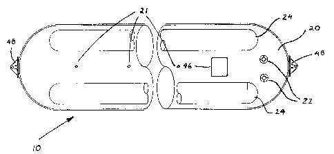
FIGURE 1 is a truncated plan view of a floating breakwater system embodying
novel
features of the invention, showing a primary barrier with two overtopping
barriers;
FIG. 2 is s side elevational view of the breakwater system shown in FIG. 1,
additionally showing in enlarged cutaway section the circumferential and
longitudinal straps
which may encase the primary barrier;
CA 02366221 2001-12-28
=
FIG. 3 is an end view of the view of the breakwater system shown in FIG. 2,
showing longitudinal straps connected to a collector plate;
FIG. 4 is an enlarged view of FIG. 3;
FIG. 5 is an enlarged cross-sectional view taken substantially along line 5-5
5 in FIG. 2;
FIG. 6 is an enlarged, fragmentary detail view of the connection between the
primary barrier and the overtopping barriers shown in FIG. 5;
FIG. 7 is a fragmentary schematic view of a vessel launching from its deck a
breakwater system embodying features of the present invention.
FIG. 8 is a fragmentary elevational view of the breakwater system shown in
FIG. 2 deployed in water and moored to the ocean floor.
FIG. 9 is a schematic perspective view, in section, of the breakwater system
of FIG. 2, deployed in water.
DETAILED DESCRIPTION OF THE PREFERRED EMBODIMENTS
Referring now to the drawings, and in particular, to FIG. 1, there is shown a
structure and system for one embodiment of a floating breakwater 10
incorporating
novel features of the present invention. Included in the breakwater is a
tubular
primary barrier 20, closed at both ends, made of flexible material and adapted
to be
expanded from a collapsed condition to an expanded condition in the deployed
state. The length of the primary barrier may preferably be in the region of
five to
fifty times its diameter, to simplify manufacture and deployment. Expansion of
the
primary barrier 20 is achieved by introducing water into its interior cavity
chamber.
The surface of the primary barrier may be configured to have at least one
sealable
opening 22, adapted to be watertight when sealed, in order to allow for the
introduction of water by a pump 46 mounted on the vessel, or, mounted on the
breakwater itself. During the process of pumping, the connection between the
pump nozzle and the sealable openings 22 may be adapted to be watertight so as
to
CA 02366221 2001-12-28
=
.=41
6
enable and maintain pressurization of the primary barrier by pumping a desired
amount of water into the cavity. Furthermore, one or more vapor relief devices
21,
adapted to allow air or vapor, but not liquid, to escape from the primary
barrier may
be installed along the top of the primary barrier, enabling the primary
barrier to be
filed completely with liquid to the exclusion of air or vapor. In one
embodiment,
the water introduced into the cavity of the primary barrier is water from the
body of
water in which the breakwater is deployed. In another embodiment, fresh water
may be used if the breakwater is deployed in the ocean, as such will provide
enhanced buoyancy of the breakwater due to the lower density of fresh water.
A preferred material for manufacturing the primary barrier 20 is a coated
textile fabric, such as a waterproof, high strength polyurethane coated
polyester
fabric material. Other flexible coating materials or other reinforcing
fabrics, such as
those made from high strength textile fiber, suitable for a marine environment
also
can be used. To minimize local stresses in the fabric, the barrier may be
configured
to have hemispherical or dome shaped ends. Prior to being deployed in the
water,
the primary barrier may be stored in a collapsed condition, most conveniently
wound onto a hydraulically powered reel or stack-folded on either the deck of
the
deploying/ retrieving vessel or on a dock for deployment and towing to the
installation site.
In its fully deployed state, the water in the cavity of the primary barrier 20
is
pressurized to a level substantially greater than the pressure of the water
surrounding the barrier. The material embodying the primary barrier 20 is
adapted
to withstand the forces introduced by such pressure. It will be appreciated by
those '
skilled in the art that, by pressurizing the water in the primary barrier 20,
the
material of the primary barrier gains wrinkle and buckle resistance, thus
enhancing
the primary barrier's overall stiffness. This increased stiffness has
beneficial effects
on the ability of the water-filled primary barrier 20 to attenuate wave
action, as it
enables the breakwater to float in the water as an effectively rigid beam.
CA 02366221 2001-12-28
7
The desired level of pressurization in the primary barrier is preferably the
pressure necessary to resist wrinkle formation in the side of the barrier that
is
exposed to both current load and wave load. (This will be the worst case,
since if
the current is applied in the opposite direction to that of the waves, their
two load
effects will tend to cancel each other.) For any pressurized thin-walled
vessel
having a diameter D, that is placed in a flowing fluid current with density p
and
velocity V, and is moored at points L distance apart, the pressure P that will
resist
wrinkling in the thin wall is given by the relationship::
Pz (pin g) (VL/D)
where g = acceleration due to gravity.
If the wave loading is expressed as a current with a velocity such as would
induce an amount of bending in the primary barrier equivalent to that induced
by
the waves, then the velocity of the actual current (Vcõ,,ent) may be added to
the
velocity of the (putative) wave induced current (Vwave induced) to give an
effective
current velocity (Veffective), as follows:
Veffective Vcurrent Vwave_induced"
Thus, in the case of a pressurized primary barrier exposed to both current and
wave action forces:
P (Pin g) (VeffectivellD) 2
From this relationship it will be seen that, for a given fluid condition and
given spacing of mooring points, the pressure required to resist wrinkle
formation
on the side of the beam exposed to current and wave action is inversely
proportional
to the square of the diameter of the barrier.
Pressurization of the water may be achieved by pumping into the cavity of
the primary barrier, via inlet ports 22, the volume of water required to
achieve the
desired pressure and level of stiffness. When fresh water is to be used, such
will
generally be pumped into the cavity while the breakwater is near the shore,
whereafter the breakwater will be towed out to its desired location. It will
be
CA 02366221 2001-12-28
=
8
appreciated that once the desired pressure is initially established, the same
may
dissipate due to leakage of the water from the primary barrier, or from
material
stretching, or from changes in temperature. Moreover, it may be found that an
initially established pressure must be increased to resist buckling and
wrinkling and
to maintain the desired stiffness for changing sea conditions. In such cases,
pumping may be resumed continuously, intermittently, or at periodic intervals
to
maintain or vary the desired water pressure after the breakwater is initially
fully
deployed and pressurized.
Moreover, it is not necessary that the desired water pressure within the
primary barrier 20 be maintained only by pumping additional water into the
cavity
of the primary barrier. The water pressure may be maintained by sealing the
primary barrier in a waterproof manner or also by pumping air or other gas
into one
or more inflatable pressurization tubes 23 (Fig. 5) with closed ends which may
be
positioned within the cavity of the primary barrier 20. A pressurization tube
23
may be fabricated from the same flexible material as the primary barrier 20.
Where
a pressurization tube is included, it will serve the additional function of
maintaining
buoyancy of the breakwater 10. Furthermore, water pressure within the primary
barrier may be maintained by adding a water reservoir, in the form of a
standpipe,
to the top surface of the barrier, containing water to a level adequate to
provide the
desired differential pressure within the primary barrier.
In a preferred embodiment, it is presently believed that the breakwater 10
will attenuate incoming waves in two ways. Short period, smaller waves may be
attenuated primarily by the inertial mass of the water in the larger diameter
pressurized primary barrier 20, and by overtopping barriers 24 which deflect
wave
crests from breaking across the primary barrier. Longer period waves may be
attenuated both by the inertial mass of the water in the primary barrier, and
by the
stiffness of the primary barrier. The stiffness of the primary barrier resists
lateral
deformation (both horizontal and vertical) of the breakwater, and thereby
reduces
the transmission of larger waves across the breakwater to the lee side.
CA 02366221 2001-12-28
9
In a further aspect of the invention, the strength and stiffness of the
primary
barrier 20 may be enhanced by enclosing the same in a flexible cylindrical
jacket,
so that the forces in the fabric of the primary barrier are transferred to the
jacket. In
this aspect of the invention, the primary barrier 20 may be adapted
principally to
contain the pressurized water within its cavity, while the jacket may be
adapted
principally to sustain the forces generated by the pressurized water and wave
action,
and simultaneously to provide increased stiffness of the breakwater 10. This
enables the primary barrier to be made from a lighter weight fabric with less
tensile
strength, if desired. In a preferred embodiment, exemplified in FIGS. 2 and 4,
the
jacket may comprise a plurality of straps, which may be longitudinal straps 28
and
circumferential straps 32 configured to enclose or surround the primary
barrier 20.
The circumferential straps 32 may be interwoven with the longitudinal straps
28,
thus providing the circumferential straps with a restraint against
longitudinal
movement. The tightness or closeness of the weave may be varied. As
exemplified
in FIG. 4, two adjacent longitudinal straps 28 may be configured to form a
continuous loop, thus permitting their ends 34 to be conveniently gathered at
the
axis of the primary barrier 20 and attached by links 40 to a collector plate
44. In an
alternative embodiment, the jacket may consist of oppositely wound straps (not
shown in such configuration) which are oriented at an oblique angle to the
axis of
the primary barrier 20, rather than being oriented parallel and at right
angles to the
axis. A preferred configuration for the obliquely wound straps is to position
oppositely wound straps in helical configuration at an angle of approximately
50 to
60 degrees, preferably 57 degrees, to the axis of the primary barrier. The
presently
preferred material from which to manufacture the straps is polyester, but
other
material made from high strength textile fibers also can be used. Both
collector
plate 44 and links 40 may be constructed from suitably non-corrosive material
such
as galvanized or stainless steel. It will be appreciated that, while the
jacket may be
made removable or permanently applied to the barrier, the jacket should be
connected to the primary bather, especially during pressurization, so as to
prevent
CA 02366221 2001-12-28
3
dislocation of the jacket from its desired position on the barrier. Simple
stitching at
intervals may be adequate to prevent such dislocation.
It is estimated that a primary barrier 20 having a diameter of between about
6 feet and 30 feet will optimally attenuate wave action in an offshore
environment,
Various factors and conditions may affect the overall optimal configuration
of the breakwater. As is apparent from the relationship set forth above, the
effective
25 Although the most appropriate pressure for a primary barrier of given
diameter is dependent on many variables, a preferable range of differential
pressures (measured as the difference between pressure internal to the barrier
and
pressure external thereto at any level) may be as follows. For barriers having
a
diameter of at least two feet, a differential pressure of at least about 10
psi may be
CA 02366221 2001-12-28
04.k.
11
preferred; for barriers having a diameter of at least 4 feet, at least about 3
psi may
be preferred; for barriers having a diameter of at least 6 feet, at least
about 1 psi is
preferred; and, for barriers having a diameter of at least 12 feet, at least
about 0.5
psi is preferred.
It is presently contemplated that barriers configured in accordance with the
present invention may be used at differential pressures ranging from about 0.5
psi
(for the largest diameters) to at least 30 psi, depending on size and
prevailing
conditions, with pressures of about 2-10 psi being common for larger diameter
systems.
In a further aspect of the present invention exemplified in FIGS. 1-5, one or
more tubular overtopping barriers 24 made of flexible material and adapted to
be
expanded from a collapsed condition to an expanded condition in the deployed
state
may be attached to the primary barrier 20 at or near the waterline. In one
embodiment, the overtopping barriers are filled with air in the deployed state
and,
preferably, have a smaller diameter than the primary barrier. In another
embodiment, the overtopping barriers may be filled with closed cell foam, or
similar buoyant material. As they are buoyant, the overtopping barriers 24
will
extend substantially above the surface of the water in the deployed state,
where they
will serve to attenuate the progress of smaller waves or the tips of larger
waves
which would otherwise crest over the primary barrier and disturb the surface
of the
water in the lee of the breakwater 10. The overtopping barriers 24 can be
constructed to perform the additional secondary functions of adding to the
stability
and overall buoyancy of the breakwater 10. Although a number of overtopping
barriers may be used, it has been found that two are preferable. A location on
top of
the primary barrier 20 within an arc of about 30 degrees on each side of the
vertical
centerline projected upward from the center of the primary barrier is
considered
suitable for this purpose.
The overtopping barriers 24 may be attached in their collapsed state to the
primary barrier 20 in its collapsed state in the manner exemplified in FIG. 6,
which
CA 02366221 2001-12-28
=
12
shows how flexible flaps 50 may be connected to both overtopping barrier 24
and
primary barrier 20 so as to overlap with each other. A plurality of grommets
54
may be inserted into the flaps to facilitate attachment using flexible
polyester cord.
The preferred material for manufacturing the overtopping barriers and the
attachment flaps is the same high strength polyurethane coated polyester
fabric
material from which the primary barrier may be manufactured. This
configuration
permits the entire breakwater 10 to remain flexible in its collapsed state,
allowing it
to be wound onto a reel or to be folded onto a dock or the deck of a vessel.
The
overtopping barrier 24 can be attached to the primary barrier 20 or to the
jacket
enclosing the primary barrier in a variety of other ways if desired.
In a further aspect of the invention, exemplified in FIG. 5, a flexible
flotation
element 36 may be attached to the upper surface of the primary barrier 20,
preferably the inside surface although the outside surface may be desirable if
water
pressure in the primary barrier is likely to compress the flotation element
and
reduce its buoyancy excessively. The flotation element 36 may be made of a
layer
of lightweight closed-cell foam, and is configured to ensure positive buoyancy
and
promote vertical orientation of the vertical centerline of the breakwater 10.
Typically, the breakwater will, overall, be configured with sufficient
buoyancy such
that the primary barrier 20 will just float at the tope of the nominal water
surface. It
will be appreciated that the flotation element 36 should be sufficiently
flexible to
permit it to be wound onto a storage reel, or to be folded, along with the
other
flexible elements of the breakwater 10.
It will further be appreciated that, in the deployed state, the space between
two adjacent overtopping barriers 24 may provide a convenient protected
walkway
when the breakwater 10 is made from sufficiently large barriers, thereby
providing
a somewhat protected platform for operation, inspection, and maintenance of
the
breakwater. Where continued pumping is required to maintain or vary the water
pressure within the cavity of the primary barrier 20, as referenced above, it
may
nevertheless become necessary for the support vessel to leave the vicinity of
the
CA 02366221 2001-12-28
(4 N,
13
breakwater. In this event, it may be desirable to mount a pump 46 on the upper
surface of the primary barrier 20 (especially where protective overtopping
barriers 24 are attached to the jacket or primary barrier) to maintain or vary
the
pressure within the primary barrier by means of continued pumping. Pumping may
be triggered, if necessary, by a switch configured to sense the pressure
within the
primary barrier and to switch on the pump when the pressure falls below a
designated level. Furthermore, where straps 28, 32 are used to strengthen and
stiffen the primary barrier, the same may form a conveniently rigid slip-
resistant
surface between the overtopping barriers 24 to facilitate movement of
personnel
along the length of the breakwater 10.
As to storage, deployment, and retrieval, FIG. 7 exemplifies how the
breakwater 10 may be stored on a hydraulically powered reel 70 on the deck 72
of a
vessel 74. A suitable method for deploying the breakwater from the deck of the
vessel may be to anchor one end at a desired location in a body of water and
then to
power the vessel away from the mooring point while unwinding from the reel and
playing out the breakwater behind the vessel. On retrieval, the primary
barrier may
be drained of its liquid contents under the effect of gravity as it is
recovered
upwards from the water onto a reel on a dock or recovery vessel.
It will be appreciated that positioning a breakwater 10 at right angles to the
direction of the approaching waves achieves the longest shadow of calm water
behind the breakwater. Depending on the prevailing conditions, it has been
found
that the breakwater of the present invention will adequately attenuate wave
action
when thus positioned. Alternatively, a breakwater 10 may be positioned at an
angle
to the direction of the approaching waves. While this orientation provides a
narrower shadow of calm water behind the breakwater, it may have the advantage
of enabling the breakwater to attenuate more energetic wave action. Whatever
length is used for each breakwater unit, it may be desirable to attach a
number of
breakwaters 10 to each other end-to-end, to form an elongated breakwater
system
which may exceed 1000 feet in length. In a variation of this aspect, the
breakwaters
CA 02366221 2001-12-28
14
may be positioned to form an arc around a specific point of interest.
Alternatively,
a series of parallel breakwater units may be positioned in staggered, shingle-
like
fashion, in the path of the oncoming waves. In a further variation, a
breakwater
system may include a plurality of barriers arranged as a "V," pointing into
the
oncoming waves, or as a "X" (lambda) with the long leg presenting a straight
barrier
positioned at an angle to the path of the oncoming waves. The ideal
orientation, in
each case, is determined by wind, current and wave conditions.
As noted above, it is estimated that a primary barrier 20 having a diameter
between about 6 feet and 30 feet will optimally attenuate wave action in an
offshore
condition, while a primary barrier having a diameter between about 2 feet and
12
feet will optimally attenuate wave action in a nearshore condition. Suitable
corresponding tubular overtopping barriers for such configurations will have a
size
of about 3 feet to 6 feet and about 1 foot to 4 feet in diameter,
respectively. When
finally positioned as desired, each breakwater structure 10 may be moored to
the
bottom, as exemplified in FIG. 8, by means of mooring lines 76, 76', 76", 76"
attached to mooring attachments 48 on the breakwater, and any suitable
anchoring
means, either on a buoy 78 or on the ocean floor. The buoy may itself be
anchored
with a mooring line 80 to the ocean floor. Mooring attachments 48, exemplified
in
FIGS 1,2 and 4, may be constructed from suitable non-corrosive material such
as
galvanized or stainless steel. In addition to mooring the breakwater by its
ends,
additional intermittent mooring lines 76" may be attached to the breakwater
intermediately between the ends, attachment being effected by using an
appropriate
load spreading attachment system (not shown). The mooring lines
serve to maintain the desired location and orientation of the breakwater
relative to
the approaching waves.
FIG. 9 exemplifies the operation of the breakwater system of the present
invention. Waves reaching the breakwater are attenuated by the inertial mass
of the
primary barrier, and any cresting over the top of the primary barrier is
reflected or
CA 02366221 2001-12-28
..toftt Arm.
attenuated by the overtopping barriers, providing an area of relative calm in
the lee
of the breakwater.
The breakwater of the present invention has the primary advantage of
maintaining an enhanced stiffness through pressurization of its fluid
contents, so
5 that the breakwater may act as a rigid beam in the water, capable of
absorbing and
attenuating wave action. Other advantages include being economical in that it
is
easy to build, to transport, to rapidly deploy and retrieve, to repair, and to
store. It
may be made primarily from inexpensive, durable fabric, which, being
lightweight
and flexible, is unlikely to cause substantive damage to vessels even in
elevated sea
10 condition conditions. Indeed, the breakwater may serve the additional
function of
buffering ships from colliding with maritime objects, and a vessel would be
able to
moor alongside the breakwater without the need for additional fendering. The
breakwater may be pressurized to maintain a desired level of stiffness to
reduce
wave action. The internal pressure of the primary barrier 20 may be controlled
as
15 necessary to provide the optimum wave suppression for a given condition.
The
materials embodying the breakwater may all be corrosion resistant materials
that
have demonstrated long-life capabilities both in the stored and deployed
environments. By fabricating the breakwater as a continuous structure,
frequent
joints can be avoided.
It will be apparent from the foregoing that, while particular forms of the
invention have been illustrated and described, various modifications can be
made
without departing from the spirit and scope of the invention. For example,
while
the drawings of the Figures illustrate primary barrier 20, overtopping barrier
24, and
pressurization tube 23 each having a circular cross section, the exact cross
sectional
shape of these elements can be varied, and may in each case assume any cross
sectional shape capable of performing the element's described function.
Accordingly, it is not intended that the invention be limited, except as by
the
appended claims.