Sélection de la langue

Search

Sommaire du brevet 2366875 

Énoncé de désistement de responsabilité concernant l'information provenant de tiers

Une partie des informations de ce site Web a été fournie par des sources externes. Le gouvernement du Canada n'assume aucune responsabilité concernant la précision, l'actualité ou la fiabilité des informations fournies par les sources externes. Les utilisateurs qui désirent employer cette information devraient consulter directement la source des informations. Le contenu fourni par les sources externes n'est pas assujetti aux exigences sur les langues officielles, la protection des renseignements personnels et l'accessibilité.

Disponibilité de l'Abrégé et des Revendications

L'apparition de différences dans le texte et l'image des Revendications et de l'Abrégé dépend du moment auquel le document est publié. Les textes des Revendications et de l'Abrégé sont affichés :

  • lorsque la demande peut être examinée par le public;
  • lorsque le brevet est émis (délivrance).
(12) Brevet: (11) CA 2366875
(54) Titre français: EXTREMITE DE PIECE A MAIN CHIRURGICALE
(54) Titre anglais: SURGICAL HANDPIECE TIP
Statut: Périmé et au-delà du délai pour l’annulation
Données bibliographiques
(51) Classification internationale des brevets (CIB):
  • A61F 09/007 (2006.01)
  • A61B 18/04 (2006.01)
  • A61B 18/14 (2006.01)
(72) Inventeurs :
  • SUSSMAN, GLENN (Etats-Unis d'Amérique)
  • PADGET, MARTIN J. (Etats-Unis d'Amérique)
  • COHEN, DONALD M. (Etats-Unis d'Amérique)
(73) Titulaires :
  • LTD. ALCON MANUFACTURING
(71) Demandeurs :
  • LTD. ALCON MANUFACTURING (Etats-Unis d'Amérique)
(74) Agent: KIRBY EADES GALE BAKER
(74) Co-agent:
(45) Délivré: 2010-02-02
(86) Date de dépôt PCT: 2000-04-18
(87) Mise à la disponibilité du public: 2000-12-21
Requête d'examen: 2005-02-01
Licence disponible: S.O.
Cédé au domaine public: S.O.
(25) Langue des documents déposés: Anglais

Traité de coopération en matière de brevets (PCT): Oui
(86) Numéro de la demande PCT: PCT/US2000/010419
(87) Numéro de publication internationale PCT: US2000010419
(85) Entrée nationale: 2001-10-04

(30) Données de priorité de la demande:
Numéro de la demande Pays / territoire Date
09/330,698 (Etats-Unis d'Amérique) 1999-06-11

Abrégés

Abrégé français

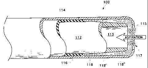
L'invention concerne une extrémité de pièce à main chirurgicale, dotée d'au moins deux tubes électroconducteurs, espacés coaxialement. Les tubes sont séparés par un isolateur pour l'électricité. L'intérieur du tube interne est utilisé pour l'aspiration de tissu liquéfié. La partie distale du tube intérieur se termine juste à l'intérieur du tube extérieur, de sorte qu'une région à bouillir soit formée. Du courant électrique est envoyé entre le tube extérieur et le tube intérieur, de sorte que le fluide chirurgical, quel qu'il soit, bouille rapidement dans la zone à bouillir. Le fluide en ébullition se dilate rapidement, sort de l'anneau entre les tubes et entre en contact avec le tissu cible, ce qui induit la liquéfaction du tissu et permet son aspiration.


Abrégé anglais


A surgical handpiece tip with at least two coaxially spaced electrically
conductive tubes. The tubes are separated by
an electrical insulator. The interior of the inner tube is used for aspiration
of liquefied tissue. The distal portion of the interior tube
terminates just inside of the outer tube so as to form a boiling region.
Electrical current is passed between the inner and outer tube to
rapidly boil any surgical fluid in the boiling region. The boiling fluid
rapidly expands out of the ring between the tubes and contacts
the targeted tissue, thereby liquefying the tissue and allowing the tissue to
be aspirated.

Revendications

Note : Les revendications sont présentées dans la langue officielle dans laquelle elles ont été soumises.


7
Claims
1. A handpiece tip comprising:
(a) an inner electrically conductive aspiration tube having a distal end;
(b) an outer electrically conductive tube having a distal end coaxially spaced
about the inner tube, the distal end of the outer tube extending distally past
the distal end
of the inner tube;
(c) an insulator spaced between the inner tube and the outer tube; and
(d) a boiling region formed by the outer tube between the distal end of the
outer tube and the distal end of the inner tube, the boiling region being
located internal to
the outer tube.
2. The tip of claim 1 wherein an electrical current flowing across the inner
tube and the outer tube is capable of boiling a fluid.
3. The tip of claim 1 wherein the inner tube has a conical distal end.
4. The tip of claim 1 wherein an electrical current flowing across the inner
tube and outer tube is capable of producing a pressure pulse force of between
0.03 grams
and 20.0 grams in a fluid.
5. A handpiece tip comprising:
(a) an inner electrically conductive aspiration tube having a conical distal
end;
(b) an outer electrically conductive tube having a distal end coaxially spaced
about the inner tube, the distal end of the outer tube extending distally past
the distal end
of the inner tube;
(c) an insulator spaced between the inner tube and the outer tube; and
(d) a boiling region formed by the outer tube between the distal end of the
outer tube and the distal end of the inner tube, the boiling region capable of
producing a
pressure pulse force of between 0.03 grams and 20.0 grams in a fluid and being
located
internal to the outer tube.

Description

Note : Les descriptions sont présentées dans la langue officielle dans laquelle elles ont été soumises.


CA 02366875 2005-11-16
SURGICAL HANDPIECE TIP
Background of the Invention
This invention relates generally to the field of minimally invasive surgery,
such as
intervertebral disc and cataract surgery and more particularly to a handpiece
for practicing
the liquefraction technique.
The human eye in its simplest terms functions to provide vision by
transmitting
light through a clear outer portion called the comea, and focusing the image
by way of the
lens onto the retina. The quality of the focused image depends on many factors
including
the size and shape of the eye, and the transparency of the cornea and lens.
When age or disease causes the lens to become less transparent, vision
deteriorates
because of the diminished light which can be transmitted to the retina. This
deficiency in
the lens of the eye is medically known as a cataract. An accepted treatment
for this
condition is surgical removal of the lens and replacement of the lens function
by an
artificial intraocular lens (IOL). -
In the United States, the majority of cataractous lenses are removed by a
surgical
technique called phacoemulsification. During this procedure, a thin
phacoemulsification
cutting tip is inserted into the diseased lens and vibrated ultrasonically.
The vibrating
cutting tip liquifies or emulsifies the lens so that the lens may be aspirated
out of the eye.
The diseased lens, once removed, is replaced by an artificial lens.
Recently, a new tissue removal technique has been developed that involves the
injection of hot (approximately 45 C to 105 C) water or saline to liquefy or
gellate tissue,
such as the hard lens nucleus, thereby making it possible to aspirate the
liquefied tissue.
Aspiration is conducted with the injection of the heated solution and the
injection of a
relatively cool solution, thereby quickly cooling and removing the heated
solution. One
application of this technique is more fully described in U.S. Patent No.
5,616,120
(Andrew, et al.). The apparatus disclosed in the publication, however, heats
the solution
separately from the surgical handpiece. Temperature control of the heated
solution can be
difficult because the fluid tubings feeding the handpiece typically are up to
two meters long,
and the heated solution can cool considerably as it travels down the length of
the tubing.

CA 02366875 2005-11-16
2
The use of electrosurgical handpieces to remove tissue is known. For example,
U.S.
Patent No. 5,009,656 (Reimels) describes an electrosurgical handpiece having
an inner and
an outer tube separated by an insulator. Current is passed between the inner
and the outer
tube to cause a spark that is used to cut tissue. This device intentionally
creates an air gap
between the electrodes to facilitate sparking, and does not use heated fluid
as the cutting
medium.
Therefore, a need continues to exist for a surgical handpiece that can heat
internally
the solution and create high pressure, high rise rate waves or pulses used to
perform the
liquefraction technique.
Brief Summary of the Invention
The present invention improves upon the prior art by providing a surgical
handpiece
having a tip with at least two coaxially spaced electrically conductive tubes.
The tubes are
separated by an electrical insulator. The interior of the inner tube is used
for aspiration of
liquefied tissue. The distal portion of the interior tube terminates just
inside of the outer
tube so as to form a boiling region. Electrical current is passed between the
inner and outer
tube to rapidly boil any surgical fluid in the boiling region. The boiling
fluid rapidly
expands out of the ring between the tube ends and forces hot fluid to contact
the targeted
tissue, thereby liquefying the tissue and allowing the tissue to be aspirated.
In accordance with one aspect of the present invention there is provided a
handpiece
tip comprising: a) an inner electrically conductive aspiration tube having a
distal end; b) an
outer electrically conductive tube having a distal end coaxially spaced about
the inner tube,
the distal end of the outer tube extending distally past the distal end of the
inner tube; c) an
insulator spaced between the inner tube and the outer tube; and d) a boiling
region formed
by the outer tube between the distal end of the outer tube and the distal end
of the inner
tube.
Accordingly, one objective of the present invention is to provide a surgical
handpiece having a tip with at least two tubes.

CA 02366875 2005-11-16
2a
Another objective of the present invention is to provide a handpiece for
practicing
the liquefraction method of tissue removal.
Another objective of the present invention is to provide a handpiece for
practicing
intervertebral disc surgery.
These and other advantages and objectives of the present invention will become
apparent from the detailed description and claims that follow.

CA 02366875 2001-10-04
WO 00/76434 PCT/US00/10419
3
Brief Description of the Drawings
FIG. 1 is a schematic, cross-sectional view of a first embodiment of a tip
that can
be used with the handpiece of the present invention.
FIG. 2 is a block diagram of a first control system that can be used with the
surgical handpiece of the present invention.
FIG. 3 is a schematic, cross-sectional view of a second embodiment a tip that
can
be used with the handpiece of the present invention.
FIG. 4 is a perspective view of a handpiece and control console that may be
used
with the present invention.
FIG. 5 is a block diagram of a second control system that can be used with the
surgical handpiece of the present invention which is similar to the control
system
illustrated in FIG. 2 except for the addition of a control valve in the
aspiration line.
Detailed Description of the Invention
As best seen in FIGS. 1 and 4, in the first embodiment of the present
invention tip
10 to be used with handpiece 9 generally includes inner tube 12 and outer tube
14
separated by insulator 16. Inner tube 12 has an inside diameter D, of between
0.010
inches and 0.050 inches, with 0.030 being preferred, and an outside diameter
of between
0.015 inches and 0.060 inches, with 0.036 inches being preferred. Outer tube
14 has an
outside diameter D2 of between 0.025 inches and 0.075 inches, with 0.045
inches being
preferred. Inner tube 12 and outer tube 14 may be made of any electrically
conductive
material, such as stainless steel or titanium tubing. Insulator 16 may be made
of any
electrically nonconductive material resistant to high temperatures, such as
polyimide,
silicone or ceramic. Insulator 16 may be any suitable thickness, but between
0.001 inches
and 0.003 inches is preferred, with 0.002 inches being most preferred.
Outer tube 14 extends distally past inner tube 12 a distance L, of between
0.010
inches and 0.030 inches, with 0.020 inches being preferred. Insulator 16 may
be flush
with inner tube 12 or may extend distally past inner tube 12 a distance L2 of
between 0.00
inches and 0.020 inches. The space between outer tube 14 and inner tube 12
forms
boiling region 18. While only two embodiments of the tip of the present
invention are

CA 02366875 2001-10-04
WO 00/76434 PCT/US00/10419
4
disclosed herein, any tip producing adequate pressure pulse force, rise time
and frequency
may also be used. For example, any suitable tip producing a pressure pulse
force of
between 0.03 grams and 20.0 grams, with a rise time of between I gram/sec and
20,000
grams/sec, with between 3000 grams/sec and 20,000 grams/sec being more
preferred and a
frequency of between 1 Hz and 400 Hz may be used, with between 25 Hz and 200
Hz
being most preferred.
In use, surgical fluid (e.g. saline irrigating solution) enters boiling region
18.
Electrical current (preferably Radio Frequency Alternating Current "RFAC") is
delivered to
and across inner tube 12 and outer tube 14 through the surgical fluid in
boiling region 18
1e because of the conductive nature of the surgical fluid. As the current
flows through
boiling region 18, the surgical fluid boils. As the surgical fluid boils, it
expands rapidly
out of tip 10. Subsequent pulses of electrical current form sequential gas
bubbles. The
size and pressure of the fluid pulse obtained by boiling region 18 can be
varied by varying
the length, timing and/or power of the electrical pulse sent to tubes 12 and
14 and by
varying the dimensions of boiling region 18.
As seen in FIGS. 2, 4 and 5, control system 300 or 300' for use in operating
handpiece 9, 311 or 311' containing tip 10, 110, 310 or 310' includes control
module 347
or 347', RF amplifier 312 or 312' and function generator 314 or 314'. Power is
supplied to
RF amplifier 312 or 312' by DC power supply 316 or 316', which preferably is
an isolated
DC power supply operating at 200 volts. Control module 347 or 347' may be any
suitable microprocessor, and may receive input from operator input device 318
or 318'.
Function generator 314 or 314' provides the electric wave form to amplifier
312 or 312'
and preferably operates at 200 KHz to 10 MHz, and more preferably between 450
KHz
and 1 MHZ, to help minimize corrosion.
In use, control module 347 or 347' receives input from surgical console 320 or
320'. Console 320 or 320' may be any commercially available surgical control
console
such as the LEGACY SERIES TWENTY THOUSAND surgical system available from
Alcon Laboratories, Inc., Fort Worth, Texas. Console 320 or 320' is connected
to
handpiece 9, 311 or 311' through irrigation line 322 or 322' and aspiration
line 324 or
324', and the flow through lines 322 or 322' and 324 or 324' is controlled by
the user via
footswitch 326 or 326'. Irrigation and aspiration flow rate information in
handpiece 9, 311
or 311' is provided to control module 347 or 347' by console 320 or 320' via
interface 328

CA 02366875 2005-11-16
or 328', which may be connected to the ultrasound handpiece control port on
console 320
or 320' or to any other output port. Control module 347 or 347' uses
footswitch 326 or
326' information provided by console 320 or 320' and operator input from input
device
318 or 318' to generate two control signals 330 or 330' and 332 or 332'.
Signal 330 or
s 330' is used to control function generator 314 or 314'. Based on signal 330
or 330',
function generator 314 or 314' provides a wave form at the operator selected
frequency
and amplitude determined by the position of footswitch 326 or 326' to RF
amplifier 312 or
312' which is amplified to advance the powered wave form to tip 10, 110, 310
or 310' to
create heated, pressurized pulses of surgical fluid.
As best seen in FIG. 5, control system 300' may also use valve 350 placed in
aspiration line 324'. Valve 350 is controlled by control module 347' to
alternate between
an open and a closed position, thereby creating pulsed aspiration flow.
As best seen in FIG. 3, in a second embodiment of the present invention, tip
110
which may be used with handpiece 9 or 311 generally includes inner tube 112
and outer
1s tube 114 separated by insulator 116. Inner tube 112 has a generally conical
distal end
113. Conical end 113 creates a boiling region 118 between inner tube 112 and
outer tube
114 that generally increases in size from region 118 to region 118' and 118".
As current
flows between outer tube 114 and inner tube 112, boiling begins at region 118
where the
electrode gap is the smallest. As the fluid in area 118 boils, the resistance
to current flow
is increased as the fluid turns to steam or vapor. In this manner, the boiling
of the fluid
moves sequentially from region 118 to region 118' and then to region 118"
where the
steam escapes out port 115 in outer tube 114 where the steam and/or heated
fluid liquefies
the targeted tissue at region 117 adjacent to port 115.
The present invention may also be used for intervertebral disc surgery, such
as
intradisc thermal annuloplasty. During this surgery, the ligaments encasing a
spinal disc
are heated to destroy invading veins and nerves and to shrink the ligaments to
seal any
tears or ruptures. This surgical procedure is more completely described in
U.S. Patent
Nos. 5,201,729, 5,433,739, 6,122,549, 5,980,504, 6,073,051, 6,007,570 and
6,095,149
which correspond to WIPO Publication No. WO 98/17190.

CA 02366875 2001-10-04
WO 00/76434 PCT/US00/10419
6
This description is given for purposes of illustration and explanation. It
will be
apparent to those skilled in the relevant art that changes and modifications
may be made to
the invention described above without departing from its scope or spirit. For
example, it
will be recognized by those skilled in the art that the present invention may
be combined
with ultrasonic and/or rotating cutting tips to enhance performance.

Dessin représentatif
Une figure unique qui représente un dessin illustrant l'invention.
États administratifs

2024-08-01 : Dans le cadre de la transition vers les Brevets de nouvelle génération (BNG), la base de données sur les brevets canadiens (BDBC) contient désormais un Historique d'événement plus détaillé, qui reproduit le Journal des événements de notre nouvelle solution interne.

Veuillez noter que les événements débutant par « Inactive : » se réfèrent à des événements qui ne sont plus utilisés dans notre nouvelle solution interne.

Pour une meilleure compréhension de l'état de la demande ou brevet qui figure sur cette page, la rubrique Mise en garde , et les descriptions de Brevet , Historique d'événement , Taxes périodiques et Historique des paiements devraient être consultées.

Historique d'événement

Description Date
Le délai pour l'annulation est expiré 2013-04-18
Lettre envoyée 2012-04-18
Accordé par délivrance 2010-02-02
Inactive : Page couverture publiée 2010-02-01
Inactive : Taxe finale reçue 2009-11-17
Préoctroi 2009-11-17
Un avis d'acceptation est envoyé 2009-06-01
Lettre envoyée 2009-06-01
Un avis d'acceptation est envoyé 2009-06-01
Inactive : CIB enlevée 2009-05-28
Inactive : Approuvée aux fins d'acceptation (AFA) 2008-12-04
Modification reçue - modification volontaire 2008-01-29
Inactive : Dem. de l'examinateur par.30(2) Règles 2007-11-07
Modification reçue - modification volontaire 2006-09-15
Inactive : Dem. de l'examinateur par.30(2) Règles 2006-05-03
Inactive : CIB de MCD 2006-03-12
Modification reçue - modification volontaire 2006-02-06
Inactive : Dem. de l'examinateur par.30(2) Règles 2005-12-28
Modification reçue - modification volontaire 2005-11-16
Inactive : Dem. de l'examinateur par.30(2) Règles 2005-08-30
Lettre envoyée 2005-02-14
Requête d'examen reçue 2005-02-01
Exigences pour une requête d'examen - jugée conforme 2005-02-01
Toutes les exigences pour l'examen - jugée conforme 2005-02-01
Inactive : Lettre officielle 2002-07-09
Inactive : Transfert individuel 2002-05-02
Inactive : Page couverture publiée 2002-03-14
Lettre envoyée 2002-03-11
Inactive : Notice - Entrée phase nat. - Pas de RE 2002-03-11
Demande reçue - PCT 2002-02-05
Demande publiée (accessible au public) 2000-12-21

Historique d'abandonnement

Il n'y a pas d'historique d'abandonnement

Taxes périodiques

Le dernier paiement a été reçu le 2009-04-02

Avis : Si le paiement en totalité n'a pas été reçu au plus tard à la date indiquée, une taxe supplémentaire peut être imposée, soit une des taxes suivantes :

  • taxe de rétablissement ;
  • taxe pour paiement en souffrance ; ou
  • taxe additionnelle pour le renversement d'une péremption réputée.

Les taxes sur les brevets sont ajustées au 1er janvier de chaque année. Les montants ci-dessus sont les montants actuels s'ils sont reçus au plus tard le 31 décembre de l'année en cours.
Veuillez vous référer à la page web des taxes sur les brevets de l'OPIC pour voir tous les montants actuels des taxes.

Historique des taxes

Type de taxes Anniversaire Échéance Date payée
Taxe nationale de base - générale 2001-10-04
Enregistrement d'un document 2001-10-04
TM (demande, 2e anniv.) - générale 02 2002-04-18 2002-04-09
TM (demande, 3e anniv.) - générale 03 2003-04-22 2003-04-08
TM (demande, 4e anniv.) - générale 04 2004-04-19 2004-04-02
Requête d'examen - générale 2005-02-01
TM (demande, 5e anniv.) - générale 05 2005-04-18 2005-04-04
TM (demande, 6e anniv.) - générale 06 2006-04-18 2006-04-03
TM (demande, 7e anniv.) - générale 07 2007-04-18 2007-04-04
TM (demande, 8e anniv.) - générale 08 2008-04-18 2008-04-02
TM (demande, 9e anniv.) - générale 09 2009-04-20 2009-04-02
Taxe finale - générale 2009-11-17
TM (brevet, 10e anniv.) - générale 2010-04-19 2010-03-30
TM (brevet, 11e anniv.) - générale 2011-04-18 2011-03-30
Titulaires au dossier

Les titulaires actuels et antérieures au dossier sont affichés en ordre alphabétique.

Titulaires actuels au dossier
LTD. ALCON MANUFACTURING
Titulaires antérieures au dossier
DONALD M. COHEN
GLENN SUSSMAN
MARTIN J. PADGET
Les propriétaires antérieurs qui ne figurent pas dans la liste des « Propriétaires au dossier » apparaîtront dans d'autres documents au dossier.
Documents

Pour visionner les fichiers sélectionnés, entrer le code reCAPTCHA :


Pour visualiser une image, cliquer sur un lien dans la colonne description du document. Pour télécharger l'image (les images), cliquer l'une ou plusieurs cases à cocher dans la première colonne et ensuite cliquer sur le bouton "Télécharger sélection en format PDF (archive Zip)" ou le bouton "Télécharger sélection (en un fichier PDF fusionné)".

Liste des documents de brevet publiés et non publiés sur la BDBC .

Si vous avez des difficultés à accéder au contenu, veuillez communiquer avec le Centre de services à la clientèle au 1-866-997-1936, ou envoyer un courriel au Centre de service à la clientèle de l'OPIC.


Description du
Document 
Date
(aaaa-mm-jj) 
Nombre de pages   Taille de l'image (Ko) 
Dessin représentatif 2002-03-12 1 11
Abrégé 2001-10-03 1 53
Dessins 2001-10-03 5 91
Revendications 2001-10-03 2 53
Description 2001-10-03 6 269
Description 2005-11-15 7 283
Revendications 2005-11-15 2 48
Revendications 2006-02-05 1 35
Revendications 2006-09-14 1 36
Dessin représentatif 2010-01-07 1 11
Rappel de taxe de maintien due 2002-03-10 1 113
Avis d'entree dans la phase nationale 2002-03-10 1 195
Courtoisie - Certificat d'enregistrement (document(s) connexe(s)) 2002-03-10 1 113
Rappel - requête d'examen 2004-12-20 1 115
Accusé de réception de la requête d'examen 2005-02-13 1 176
Avis du commissaire - Demande jugée acceptable 2009-05-31 1 162
Avis concernant la taxe de maintien 2012-05-29 1 172
PCT 2001-10-03 4 138
PCT 2001-10-04 3 133
Correspondance 2002-07-08 1 14
Correspondance 2009-11-16 1 35