Sélection de la langue

Search

Sommaire du brevet 2372845 

Énoncé de désistement de responsabilité concernant l'information provenant de tiers

Une partie des informations de ce site Web a été fournie par des sources externes. Le gouvernement du Canada n'assume aucune responsabilité concernant la précision, l'actualité ou la fiabilité des informations fournies par les sources externes. Les utilisateurs qui désirent employer cette information devraient consulter directement la source des informations. Le contenu fourni par les sources externes n'est pas assujetti aux exigences sur les langues officielles, la protection des renseignements personnels et l'accessibilité.

Disponibilité de l'Abrégé et des Revendications

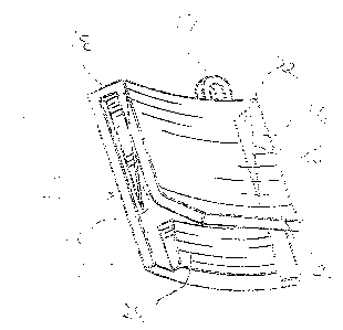
L'apparition de différences dans le texte et l'image des Revendications et de l'Abrégé dépend du moment auquel le document est publié. Les textes des Revendications et de l'Abrégé sont affichés :

  • lorsque la demande peut être examinée par le public;
  • lorsque le brevet est émis (délivrance).
(12) Demande de brevet: (11) CA 2372845
(54) Titre français: DISPOSITIF DE DEROULEMENT PERIPHERIQUE D'UNE COURONNE EXTERIEURE DE COUPELLE EN MATIERE SOUPLE
(54) Titre anglais: DEVICE FOR UNROLLING A CIRCUMFERENTIALLY EXTENDING PORTION OF AN OUTWARDLY ROLLED RIM OF A CUP MADE OF FLEXIBLE MATERIAL
Statut: Réputée abandonnée et au-delà du délai pour le rétablissement - en attente de la réponse à l’avis de communication rejetée
Données bibliographiques
Abrégés

Abrégé anglais


A device for unrolling a circumferentially extending portion of an outwardly
rolled rim of
a cup made of flexible material has a main body with spaced front and rear
wall portions connected
together at their upper ends to form a U-shape in side view to enable the
device to be placed over
the rim of a cup with the front wall portion inside the wall and the rear wall
portion outside the cup.
The main body has two laterally spaced blade members within the U-shape with
downwardly facing
cutting edges, the rear wall portion having a forwardly projecting unrolling
member below the blade
members. When the device has been positioned on the cup, downward movement of
the device
causes the unrolling member to pass below the rim and the blade members to cut
through the rim
at circumferentially spaced positions to form a cut rim portion. Subsequent
upper movement of
the device causes the unrolling member to engage and unroll the cut rim
portion.

Revendications

Note : Les revendications sont présentées dans la langue officielle dans laquelle elles ont été soumises.


CLAIMS
1. ~A device for unrolling a circumferentially extending portion of an
outwardly rolled rim of
a cup made of flexible material, said device having:
a main body with spaced front and rear wall portions connected together at
their upper ends
to form a U-shape in side view to enable the device to be placed over the rim
of a cup with the front
wall portion inside the wall and the rear wall portion outside the cup,
the main body having two laterally spaced blade members within the U-shape
with
downwardly facing cutting edges, the rear wall portion having a forwardly
projecting unrolling
member below the blade members,
whereby, when the device has been positioned on the cup, downward movement of
the
device causes the unrolling member to pass below the rim and the blade members
to cut through
the rim at circumferentially spaced positions to form a cut rim portion, and
subsequent upper
movement of the device causes the unrolling member to engage and unroll the
cut rim portion.
2. ~A rim unrolling device according to claim 1 wherein the front wall portion
has an outwardly
inclined lowermost part to facilitate positioning the device on the rim of a
cup.
-5-

Description

Note : Les descriptions sont présentées dans la langue officielle dans laquelle elles ont été soumises.

CA 02372845 2002-02-19
DEVICE FOR UNROLLING A CIRCUMFERENTIALLY EXTENDING
PORTION OF AN OUTWARDLY ROLLED RIM OF A CUP
MADE OF FLEXIBLE MATERIAL
FIELD OF INVENTION
[0001] This invention relates to a device for unrolling a circumferentially
extending portion of an
outwardly rolled rim of a cup made of flexible material.
BACKGROUND OF INVENTION
[0002] Cups made of a flexible material such as paper, paper wax or cardboard
and having an
outwardly rolled rim have been used for many years for liquids such as coffee.
It is also
known to provide information, such as contest information, on a
circumferentially extending
portion of the outwardly rolled rim so that such information is normally
hidden. A person
has to unroll that portion of the rim to reveal the information. This is
usually done by use
of the person's hand or hands and requires a certain amount of dexterity.
(0003] It is an object of this invention to provide a device which simplifies
the unrolling procedure
described above.
SUMMARY OF INVENTION
[0004] According to the invention, a rim unrolling device has a main body with
spaced front and
rear wall portions connected together at their upper ends to form a U-shape in
side view to
enable the device to be placed over the rim of a cup with the front wall
portion inside the
cup and the rear wall portion cup. The main body has two laterally spaced
blade members
within the U-shape with downwardly facing cutting edges, and the rear wall
portion has a
forwardly projecting unrolling member below the blade members. When the device
has
been positioned on the cup, downward movement of the device causes the
unrolling member
to pass below the rim and the blade members to cut through the rim at
circumferentially
-1-

CA 02372845 2002-02-19
spaced positions to form a cut rim portion, and subsequent upward movement of
the device
causes the unrolling member to engage and unroll the cut rim portion.
DESCRIPTION OF THE DRAWINGS
[0005] One embodiment of the present invention will now be described, by way
of example, with
reference to the accompanying drawings, of which:
[0006] Fig. 1 is a front perspective view of a rim unrolling device in
accordance with one
embodiment of the invention,
[0007] Fig. 2 is a rear perspective view thereof,
[0008] Fig. 3 is a front view,
[0009] Fig. 4 is a rear view,
[0010] Fig. 5 is a side view,
[0011] Fig. 6 is a top view,
[0012) Fig. 7 is a bottom view,
[0013] Fig. 8 is a sectional view taken along the line 8-8 of Fig. 3,
[0014] Fig. 9 is a perspective view showing the rim unrolling device about to
be used,
(0015] Fig. 10 is a similar view showing the rim unrolling device in initial
engagement with a cup,
-2-

CA 02372845 2002-02-19
[0016] Fig, 10a is a sectional view showing the initial engagement in more
detail,
[0017] Fig. 11 is a perspective view showing the rim unrolling device pushed
down over the rim
of the cup,
[0018] Fig. 1 l a is a sectional view showing the pushed down position in more
detail,
[0019] Fig. 12 is a perspective view showing the rim unrolling device being
moved upwardly,
[0020) Fig. 12a is a sectional view showing the upward movement in more
detail,
[0021] Fig. 13 is a perspective view of the cup showing an unrolled portion of
the rim, and
[0022] Fig. 14 is a similar view from another orientation.
DESCRIPTION OF PREFERRED EMBODIMENT
[0023] Referring to the drawings, a rim unrolling device has a main body 12 of
synthetic plastic
material with spaced transversely curved front and rear wall portions 14, 16
connected
together at their upper ends by a connection portion 18 to form a U-shape in
side view. The
main body 12 has two laterally spaced blade members 20, 22 within the U-shape
and
partially embedded in the main body 12 so that the blade members 20, 22 are
retained
therein. The blade members 20, 22 have downwardly facing cutting edges 24, 26.
The rear
wall portion 16 has a forwardly projecting unrolling member 28 below the blade
members
20, 22, and the front wall portion 14 has an outwardly inclined lowermost
portion 30 to
facilitate initial positioning of the device on a cup.
[0024] In use, the device is positioned on a cup 32 with an outwardly rolled
rim 34 so that the front
wall portion 14 is inside the cup 32 and the rear wall portion 16 is inside
the cup 32. The
-3-

CA 02372845 2002-02-19
device is then pushed downwardly to cause the unrolling member 28 to pass
below the rim
34 and the blade members 20, 22 to cut through the rim 34 at circumferentially
spaced
positions to form a cut rim portion 36. The device is then pulled upwardly to
cause the
unrolling member 28 to engage and unroll the cut rim portion 36. A person can
then read
whatever is written on the cut rim portion 36.
(0025) A small integral loop 19 may be provided on connecting portion 18 to
enable the device to
be mounted on a key ring or chain or other key holder. Also, the front and/or
rear wall
portions 14, 16 may carry advertising material.
[0026] The advantages of the invention will now be readily apparent to a
person skilled in the art
from the foregoing description of the preferred embodiment. Other embodiments
and
advantages will also now be readily apparent, the scope of the invention being
defined in
the appended claims.
::ODMA1PCDOCS1F1AM LAW12173211
February 7, 2002
-4-

Dessin représentatif
Une figure unique qui représente un dessin illustrant l'invention.
États administratifs

2024-08-01 : Dans le cadre de la transition vers les Brevets de nouvelle génération (BNG), la base de données sur les brevets canadiens (BDBC) contient désormais un Historique d'événement plus détaillé, qui reproduit le Journal des événements de notre nouvelle solution interne.

Veuillez noter que les événements débutant par « Inactive : » se réfèrent à des événements qui ne sont plus utilisés dans notre nouvelle solution interne.

Pour une meilleure compréhension de l'état de la demande ou brevet qui figure sur cette page, la rubrique Mise en garde , et les descriptions de Brevet , Historique d'événement , Taxes périodiques et Historique des paiements devraient être consultées.

Historique d'événement

Description Date
Inactive : CIB de MCD 2006-03-12
Demande non rétablie avant l'échéance 2006-02-20
Le délai pour l'annulation est expiré 2006-02-20
Réputée abandonnée - omission de répondre à un avis sur les taxes pour le maintien en état 2005-02-21
Lettre envoyée 2004-01-19
Toutes les exigences pour l'examen - jugée conforme 2003-12-23
Requête d'examen reçue 2003-12-23
Exigences pour une requête d'examen - jugée conforme 2003-12-23
Demande publiée (accessible au public) 2003-08-19
Inactive : Page couverture publiée 2003-08-18
Inactive : Correspondance - Formalités 2003-05-13
Inactive : CIB en 1re position 2002-05-02
Inactive : Certificat de dépôt - Sans RE (Anglais) 2002-03-20
Demande reçue - nationale ordinaire 2002-03-20

Historique d'abandonnement

Date d'abandonnement Raison Date de rétablissement
2005-02-21

Taxes périodiques

Le dernier paiement a été reçu le 2003-12-22

Avis : Si le paiement en totalité n'a pas été reçu au plus tard à la date indiquée, une taxe supplémentaire peut être imposée, soit une des taxes suivantes :

  • taxe de rétablissement ;
  • taxe pour paiement en souffrance ; ou
  • taxe additionnelle pour le renversement d'une péremption réputée.

Les taxes sur les brevets sont ajustées au 1er janvier de chaque année. Les montants ci-dessus sont les montants actuels s'ils sont reçus au plus tard le 31 décembre de l'année en cours.
Veuillez vous référer à la page web des taxes sur les brevets de l'OPIC pour voir tous les montants actuels des taxes.

Historique des taxes

Type de taxes Anniversaire Échéance Date payée
Taxe pour le dépôt - petite 2002-02-19
TM (demande, 2e anniv.) - petite 02 2004-02-19 2003-12-22
Requête d'examen - petite 2003-12-23
Titulaires au dossier

Les titulaires actuels et antérieures au dossier sont affichés en ordre alphabétique.

Titulaires actuels au dossier
PAUL S. ACCADIA
Titulaires antérieures au dossier
S.O.
Les propriétaires antérieurs qui ne figurent pas dans la liste des « Propriétaires au dossier » apparaîtront dans d'autres documents au dossier.
Documents

Pour visionner les fichiers sélectionnés, entrer le code reCAPTCHA :


Pour visualiser une image, cliquer sur un lien dans la colonne description du document. Pour télécharger l'image (les images), cliquer l'une ou plusieurs cases à cocher dans la première colonne et ensuite cliquer sur le bouton "Télécharger sélection en format PDF (archive Zip)" ou le bouton "Télécharger sélection (en un fichier PDF fusionné)".

Liste des documents de brevet publiés et non publiés sur la BDBC .

Si vous avez des difficultés à accéder au contenu, veuillez communiquer avec le Centre de services à la clientèle au 1-866-997-1936, ou envoyer un courriel au Centre de service à la clientèle de l'OPIC.


Description du
Document 
Date
(aaaa-mm-jj) 
Nombre de pages   Taille de l'image (Ko) 
Dessin représentatif 2002-06-05 1 18
Dessins 2003-05-12 6 108
Description 2002-02-18 4 138
Abrégé 2002-02-18 1 26
Dessins 2002-02-18 6 319
Revendications 2002-02-18 1 31
Certificat de dépôt (anglais) 2002-03-19 1 164
Rappel de taxe de maintien due 2003-10-20 1 106
Accusé de réception de la requête d'examen 2004-01-18 1 174
Courtoisie - Lettre d'abandon (taxe de maintien en état) 2005-04-17 1 174
Correspondance 2002-03-19 1 26
Correspondance 2003-05-12 7 134
Taxes 2003-12-21 1 31