Sélection de la langue

Search

Sommaire du brevet 2372944 

Énoncé de désistement de responsabilité concernant l'information provenant de tiers

Une partie des informations de ce site Web a été fournie par des sources externes. Le gouvernement du Canada n'assume aucune responsabilité concernant la précision, l'actualité ou la fiabilité des informations fournies par les sources externes. Les utilisateurs qui désirent employer cette information devraient consulter directement la source des informations. Le contenu fourni par les sources externes n'est pas assujetti aux exigences sur les langues officielles, la protection des renseignements personnels et l'accessibilité.

Disponibilité de l'Abrégé et des Revendications

L'apparition de différences dans le texte et l'image des Revendications et de l'Abrégé dépend du moment auquel le document est publié. Les textes des Revendications et de l'Abrégé sont affichés :

  • lorsque la demande peut être examinée par le public;
  • lorsque le brevet est émis (délivrance).
(12) Demande de brevet: (11) CA 2372944
(54) Titre français: DISPOSITIF AMELIORANT LE FONCTIONNEMENT HIVERNAL D'UN OUTIL PORTATIF ACTIONNE PAR MOTEUR A COMBUSTION
(54) Titre anglais: DEVICE THAT IMPROVES THE PERFORMANCE OF A PORTABLE ENGINE POWERED TOOL DURING WINTER CONDITIONS
Statut: Réputée abandonnée et au-delà du délai pour le rétablissement - en attente de la réponse à l’avis de communication rejetée
Données bibliographiques
(51) Classification internationale des brevets (CIB):
  • F02G 05/02 (2006.01)
  • B25F 05/00 (2006.01)
  • F02B 63/02 (2006.01)
  • F02B 77/11 (2006.01)
  • F02M 31/04 (2006.01)
(72) Inventeurs :
  • ANDERSSON, MAGNUS (Suède)
  • OTTOSSON, FREDRIK (Suède)
(73) Titulaires :
  • AKTIEBOLAGET ELECTROLUX
(71) Demandeurs :
  • AKTIEBOLAGET ELECTROLUX (Suède)
(74) Agent: SMART & BIGGAR LP
(74) Co-agent:
(45) Délivré:
(22) Date de dépôt: 2002-02-25
(41) Mise à la disponibilité du public: 2002-08-28
Licence disponible: S.O.
Cédé au domaine public: S.O.
(25) Langue des documents déposés: Anglais

Traité de coopération en matière de brevets (PCT): Non

(30) Données de priorité de la demande:
Numéro de la demande Pays / territoire Date
0100680-8 (Suède) 2001-02-28

Abrégés

Abrégé anglais


Engine-driven portable tools are widely used for different kinds of work where
the
surrounding conditions are very different. Large variations in temperature can
cause
problems for the engine, especially durring low temperatures that occur during
winter.
The present invention reduces these problems in a simple and effective way by
guiding heated air from the area adjacent to the muffler through a channel
placed
outside the casing to the air inlet for the engine. The cold air sucked into
the engine is
mixed with the heated air from the channel so that the temperature of the air
mixture
is increased.

Revendications

Note : Les revendications sont présentées dans la langue officielle dans laquelle elles ont été soumises.


6
Claims:
1. Device for a combustion engine-driven portable tool, wherein heated air
from
an area adjacent a muffler of the engine is led through a detachable channel
outside the tool to an air inlet to the engine.
2. Device according to claim 1, wherein the combustion engine is surrounded by
a casing (10).
3. Device according to claim 2, wherein a shell (20) is attached to the casing
(10)
so that a channel is created between the shell (20) and the casing (10).
4. Device according to claim 3,wherein the shell (20) is secured to the casing
(I0) by screws that keep different parts of the casing (10) in place.
5. Device according to claim 3, wherein the shell (20) is secured at fastening
points on the surface of the casing (10).
6. Device according to claim 2, wherein a first end of the channel is
connected to
the air inlet to the engine and a second end of the channel is connected to an
opening (15) in the casing (10) adjacent to the muffler.
7. Device according to claim 6, wherein the first end of the channel is shaped
to
only cover part of the air inlet (11, 12, 13, 14).
8. Device according to claim 5, wherein the second end of the channel is
shaped
to only partially covers the opening (15).
9. Device according to claim 3, wherein the shell (20) is shaped to prevent
snow
from entering one of the air inlet (11, 12, 13, 14) and the opening (15) in
the
casing (10).
10. Device according to claim 3, wherein the shell (20) is manufactured of a
material that is resistant to wear, impact and high temperature.

7
11. Device according to claim 10, wherein the material comprises one of
aluminum and a plastic material.

Description

Note : Les descriptions sont présentées dans la langue officielle dans laquelle elles ont été soumises.

CA 02372944 2002-02-25
DEVICE THAT IMPROVES THE PERFORMANCE OF A PORTABLE ENGINE POWERED
TOOL DURING WINTER CONDITIONS
$ACICCrItOUND OF THE INVENTION
The present invention relates to a device for improving the perforrrtance of a
portable
engine-powered tool during winter conditions-
Portable engine powered tools are widely used for different kinds of work. The
environmental conditions to which the tools are exposed can therefore vary
greatly
depending upon the type of tool, the season, and the climate of the region
where the
tool is used. It is therefore not possible to make tools that will perform
ideally in
every possible environment For example, chauusaws are used almost everywhere
in
the world, from raizzfotests to forests in theca far north. The air
temperature can vary
between several degrees below zero in combination with snow and up to very
high
temperatures during summertime in sunshine.
The considerable variation in tennperature is one parameter that heavily
affects the
performance of the engine. The greatest problems occur when the temperature is
low.
Another parameter of great importance to engine performance is the humidity of
the
air. 'The combination of low temperature and a high humidity is devastating
for the
tool. When such cold humid air passes over passages and nozzles in the engine;
it
causes a temperaturve drop in the air, which in turn causes the water in the
air to
condensate and freezx into ice that blocks the passages and nozzles.
Another problem during wintertime use is snow. powdery snow in combination
with
the above-described parameters is especially a problem since the snow can get
into
the tool. Heavy snow may block the air inlet to the tool's engine, while
lighter snow
may be sucked into the air inlet with the air. Snow that has been sucked
inside of the
tool melts and then refreezes in the passages and nozzles causing them to be
blocked.
Difl"erent approaches have been tried inn order to find a solution to the
above-described
problems. Qne approach is to guide heated air from the engine's exhaust
through a
channel inside the casing of the tool to the air inlet to coxaapensate far the
low
tem~rature air in the surrounding. However, this approach has some drawbacks.
First
of all is it difficult to create a channel that will work properly inside the
narrow casing

CA 02372944 2002-02-25
7
without increasing the size or the casing. Secondly, the channel must be
repeatedly
opened and closed depending upon the surrounding conditions. This could either
be
done by providing a complicated device on the outside of tJxe casing or by
opening the
casing anal activating or deactivating the channel inside the casing. The last
altemiative
is not desirable due to the rislt of dxopping parts while the casing is open,
especially if
there is a lot of snow. There is also a risk that equipment inside the casing
will be
damaged. Both of these alternatives are cozzsequently quite complicated and
there is a
need for a simpler solution to the above-described problems.
BRIEF SX1MMARY pF THE 1NVENTIpIV
The present invention solves the above-described problems by guiding heated
air
from the area around the muffler to the air inlet to the engine. This is done
by first
guiding the air through an opening in the casing and then through a channel
placed on
the outside of the casing. The channel ends before reaching the air inlet to
the engine
allowing the heated air to mix with the colder ambient air before being sucked
into the
engine. The temperature of the air mixture will then be high enough to prevent
he
water in the air from .fxeezing. ~n , Rassages and nozzles inside the engine
or the
carburetor.
A chaynel placed on the outside of the casing has several advantages since it
addresses the described problems in a sitople way. The casing of the tool,
such as a
chainsaw, can be designed in a compact way, since the channel, or other
arrangement
for preheating the air for the engine, is not located inside the casing. if
the chainsaw is
used outside in printer conditions, the channel can be easily attached on the
outside of
the casing without risking damage or loss of components. The attached channel
also
serves to protect against snow getting into openings in the casing since the
channel
covers some of these openings. Another advantage of the present invention is
that the
area around the carburetor zs also heated, which is favorable for the
performance of
the engine during winter conditions when the air temperature is low.
The ehannel,is necessarily maneafaciured of a~ material that is strong and
wear-resistant
since the attached channel may be exposed to a Iot of i~nnpact az~d wear. The
weight of
the channel is kept as low as possible in order to minimize the weight that
must be
carried by the operator. '1"lae channel may be secured to the casing by
apptaptiate

CA 02372944 2002-02-25
3
means depending upon the designs of the channel and the casing. One example xs
to
secure the channel to the casing by using the same screws that secure
different parts
of the casing to each other. The channel could also be attached, for example,
by
providing the channel with hooks that can be attached to corresponding
receiving
means located on proper places on the casing, 'fhe above examples could be
combined in order to further assist the operator in securing the channel to
the casing.
The attachable channel on the outside of the casing of the present invention
can also
be designed to match older chainsaws already on the market which will make it
possible to improve their performance during winter conditions.
13R.IEF DESCRIPTION OF THE SEVERAL VIEWS OF THE DR.A.WING
Figures I-4 illustrate an embodiment of the present invention designed for use
in
combination with a chain saw.
Figure 1 is a side view of a casing for a chain saw according to the present
inventioia;
Figure 2 is an elevational view of a shell for formzng a channel according to
the
present invention;
Figure 3 is a side view of the shell of Figure 2; and
Figure 4 is a view of the shell of Figures 2 and 3 secured to the casing of
Figure 1.
DETAILED DESCRIPTION OF THE INVENTION
Figure I illustrates a casting 10 used for a cha3nsaw (not shown). The casing
10 has
four differezit air inlets I I, 12, 13 and l4~on the side of the casing 10 to
provide the
engine (not shown) of the chainsaw with air_ There is also an opening 15 in
the casing
adjacent to a muffler {not shown) for the engine placed inside the casing 10.
Figures 2 and 3 illustrate a shell z0 used for chainsaws. The shell 20 has a U-
shaped
section 2I. The edges of the U~shapEd section 21 are in contact with the
casing 10 of
the chainsaw so that it creates a channel between the shell 20 and the casing
10 of the
chainsaw. The shell 24 can alternatively be shaped like a pipe to create the
channel
instead of using the casing la as a part of the channel. The cross section of
the
channel is big enough to let the warm air pass easily. The shell 20 is
provided with a
hole 22 fox securing the shell 20 to the casing 10 with a screw. The shell 20
is also

CA 02372944 2002-02-25
4
provided with a couple of hooks 23 for securing the shell 20 to the casing 10
of the
chainsaw.
The shelf 20 is attached to the casing 10 by placing the hvalcs 23 between two
halves
of the casing 10. When the ~toolcs 23 are positioned correctly, the.shell 20
is secured
to the casing 10 by a screw passing through the hole 22 ox1 the shell 20 and
then
fastened into a fastening post 16 of the casing 10.
Alternatively, the securing of the shell 20 to the casing could be done by one
or more
different means. The shell 20 could be fastened to the casing 10 by the same
screws
that keep the different parts of the casing 10 in the right position as an
alternative to
being secured by screws provided just for the shell 20. In order to reduce the
number
of screws, is it conyez~ient to provide .hooks 23 to the shell 20 that can be
secured
either between the different parts of the casing 10 or into corresponding
fastening
devices.
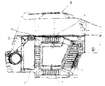
pigure a illustrates the shell 20 attached to the casing 10 so that a channel
is created
between the opening IS adjacent to the muffler axed tile air inlets l I and
i2. lfeated air
is thereby led from the area around the znufller to the inlets I Z and 12
where the
heated air is sucked into the engine. The inlet 1a not covered by the shell 20
suck in
cold air from the surrounding and it is thereby possible to control the
mixture of
heated and coil air supplied to the engine by affecting the design of the
shell 20_
The channel could be arranged in different ways between the opening 15 and the
inlets 11, 12, 13, 14 along the surface of the casing 10 in order to optimize
the weight
distribution and he shape of the chainsaw, and also to minimize the amount of
wear
on the shell 20. Dne part. 2 t , of the , shell 20,.covers the opening 15 in
the casing 10_
The heated air is then led through the created channel between the shell 20
and the
surface of the casattg 10.
The design of the shell 20, according to the illustrated embodiment, z'esults
in the shell
20 covering the inlets I l, 12 and 13_ This is an advantage since snow easily
can pass
into these Lower inlets 11, 12 and f3 during use or when the chainsaw is put
down in
the snow, fox example during a break.

CA 02372944 2002-02-25
T'he shell 20 can be nxanufactured in different shapes from an appropriate a
material
that meets the demands of a particular applicat3ion. The position of the shell
20 on the
outside of the casing 10 exposes it to a lot of impact and wear. In the
present
embodiment, the shell 20 is therefore made of aluminum or a strong plastic
material.

Dessin représentatif
Une figure unique qui représente un dessin illustrant l'invention.
États administratifs

2024-08-01 : Dans le cadre de la transition vers les Brevets de nouvelle génération (BNG), la base de données sur les brevets canadiens (BDBC) contient désormais un Historique d'événement plus détaillé, qui reproduit le Journal des événements de notre nouvelle solution interne.

Veuillez noter que les événements débutant par « Inactive : » se réfèrent à des événements qui ne sont plus utilisés dans notre nouvelle solution interne.

Pour une meilleure compréhension de l'état de la demande ou brevet qui figure sur cette page, la rubrique Mise en garde , et les descriptions de Brevet , Historique d'événement , Taxes périodiques et Historique des paiements devraient être consultées.

Historique d'événement

Description Date
Demande non rétablie avant l'échéance 2007-02-26
Le délai pour l'annulation est expiré 2007-02-26
Inactive : CIB de MCD 2006-03-12
Réputée abandonnée - omission de répondre à un avis sur les taxes pour le maintien en état 2006-02-27
Lettre envoyée 2003-01-15
Inactive : Transfert individuel 2002-11-29
Demande publiée (accessible au public) 2002-08-28
Inactive : Page couverture publiée 2002-08-27
Inactive : CIB attribuée 2002-05-03
Inactive : CIB en 1re position 2002-05-03
Modification reçue - modification volontaire 2002-04-26
Inactive : Correspondance - Formalités 2002-04-26
Inactive : Correspondance - Formalités 2002-04-23
Modification reçue - modification volontaire 2002-04-23
Inactive : Lettre de courtoisie - Preuve 2002-03-26
Inactive : Certificat de dépôt - Sans RE (Anglais) 2002-03-21
Demande reçue - nationale ordinaire 2002-03-21

Historique d'abandonnement

Date d'abandonnement Raison Date de rétablissement
2006-02-27

Taxes périodiques

Le dernier paiement a été reçu le 2005-01-24

Avis : Si le paiement en totalité n'a pas été reçu au plus tard à la date indiquée, une taxe supplémentaire peut être imposée, soit une des taxes suivantes :

  • taxe de rétablissement ;
  • taxe pour paiement en souffrance ; ou
  • taxe additionnelle pour le renversement d'une péremption réputée.

Les taxes sur les brevets sont ajustées au 1er janvier de chaque année. Les montants ci-dessus sont les montants actuels s'ils sont reçus au plus tard le 31 décembre de l'année en cours.
Veuillez vous référer à la page web des taxes sur les brevets de l'OPIC pour voir tous les montants actuels des taxes.

Historique des taxes

Type de taxes Anniversaire Échéance Date payée
Taxe pour le dépôt - générale 2002-02-25
Enregistrement d'un document 2002-11-29
TM (demande, 2e anniv.) - générale 02 2004-02-25 2004-01-13
TM (demande, 3e anniv.) - générale 03 2005-02-25 2005-01-24
Titulaires au dossier

Les titulaires actuels et antérieures au dossier sont affichés en ordre alphabétique.

Titulaires actuels au dossier
AKTIEBOLAGET ELECTROLUX
Titulaires antérieures au dossier
FREDRIK OTTOSSON
MAGNUS ANDERSSON
Les propriétaires antérieurs qui ne figurent pas dans la liste des « Propriétaires au dossier » apparaîtront dans d'autres documents au dossier.
Documents

Pour visionner les fichiers sélectionnés, entrer le code reCAPTCHA :


Pour visualiser une image, cliquer sur un lien dans la colonne description du document. Pour télécharger l'image (les images), cliquer l'une ou plusieurs cases à cocher dans la première colonne et ensuite cliquer sur le bouton "Télécharger sélection en format PDF (archive Zip)" ou le bouton "Télécharger sélection (en un fichier PDF fusionné)".

Liste des documents de brevet publiés et non publiés sur la BDBC .

Si vous avez des difficultés à accéder au contenu, veuillez communiquer avec le Centre de services à la clientèle au 1-866-997-1936, ou envoyer un courriel au Centre de service à la clientèle de l'OPIC.


Description du
Document 
Date
(aaaa-mm-jj) 
Nombre de pages   Taille de l'image (Ko) 
Dessin représentatif 2002-05-16 1 64
Description 2002-02-24 5 259
Abrégé 2002-02-24 1 22
Revendications 2002-02-24 2 48
Dessins 2002-02-24 6 401
Certificat de dépôt (anglais) 2002-03-20 1 164
Courtoisie - Certificat d'enregistrement (document(s) connexe(s)) 2003-01-14 1 107
Rappel de taxe de maintien due 2003-10-27 1 106
Courtoisie - Lettre d'abandon (taxe de maintien en état) 2006-04-23 1 177
Rappel - requête d'examen 2006-10-25 1 116
Correspondance 2002-03-20 1 26
Correspondance 2002-04-22 3 117
Correspondance 2002-04-25 3 95