Sélection de la langue

Search

Sommaire du brevet 2375400 

Énoncé de désistement de responsabilité concernant l'information provenant de tiers

Une partie des informations de ce site Web a été fournie par des sources externes. Le gouvernement du Canada n'assume aucune responsabilité concernant la précision, l'actualité ou la fiabilité des informations fournies par les sources externes. Les utilisateurs qui désirent employer cette information devraient consulter directement la source des informations. Le contenu fourni par les sources externes n'est pas assujetti aux exigences sur les langues officielles, la protection des renseignements personnels et l'accessibilité.

Disponibilité de l'Abrégé et des Revendications

L'apparition de différences dans le texte et l'image des Revendications et de l'Abrégé dépend du moment auquel le document est publié. Les textes des Revendications et de l'Abrégé sont affichés :

  • lorsque la demande peut être examinée par le public;
  • lorsque le brevet est émis (délivrance).
(12) Brevet: (11) CA 2375400
(54) Titre français: MACHINE ELECTRIQUE
(54) Titre anglais: ELECTRICAL MACHINE
Statut: Durée expirée - au-delà du délai suivant l'octroi
Données bibliographiques
(51) Classification internationale des brevets (CIB):
  • H02K 03/28 (2006.01)
  • B60K 07/00 (2006.01)
  • H02K 21/24 (2006.01)
(72) Inventeurs :
  • KRISTOFFERSEN, BJORN (Norvège)
(73) Titulaires :
  • SMART MOTOR AS
(71) Demandeurs :
  • SMART MOTOR AS (Norvège)
(74) Agent: MARKS & CLERK
(74) Co-agent:
(45) Délivré: 2008-08-05
(86) Date de dépôt PCT: 2000-05-25
(87) Mise à la disponibilité du public: 2000-12-14
Requête d'examen: 2004-05-12
Licence disponible: S.O.
Cédé au domaine public: S.O.
(25) Langue des documents déposés: Anglais

Traité de coopération en matière de brevets (PCT): Oui
(86) Numéro de la demande PCT: PCT/NO2000/000174
(87) Numéro de publication internationale PCT: NO2000000174
(85) Entrée nationale: 2001-11-26

(30) Données de priorité de la demande:
Numéro de la demande Pays / territoire Date
19992487 (Norvège) 1999-05-25

Abrégés

Abrégé français

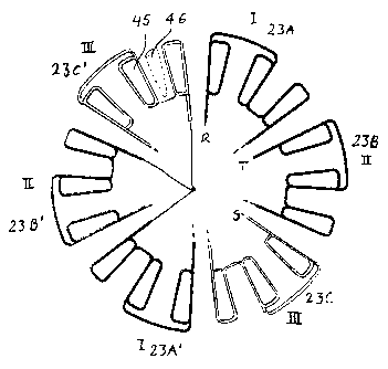
L'invention concerne une machine électrique à déplacement lent, telle qu'un moteur ou un générateur ou un moteur-générateur combiné, comprenant un ensemble annulaire d'enroulements (23) sur des noyaux de fer (45) de feuilles laminées ou de poudre de fer comprimée et un ensemble annulaire correspondant d'aimants permanents (369). Cette invention concerne notamment une machine synchrone aimantée en permanence (PMSM) destinée à une tension sinusoïdale. Les enroulements sont concentrés, non distribués dans des rainures, et des noyaux d'enroulement (45) sont disposés en alternance avec des noyaux de fer (45) dépourvus d'enroulements. Chaque second noyau de fer est pourvu d'un enroulement, le nombre de rainures ou d'intervalles entre les noyaux et le nombre de pôles étant différents. Le nombre de rainures s et le nombre de pôles p suivent les équations |s-p!=2*m et s=12*n*m, où n et m sont des entiers naturels. La machine électrique est construite pour une tension triphasée, avec une connexion en série de bobines attenantes, pour constituer de tels groupes 2*m par phase, qui peuvent être connectés en série ou en parallèle. Ce moteur peut être utilisé en tant que moteur de roue pour un véhicule.


Abrégé anglais


Slow moving electrical machine, such as a motor or a generator or a combined
motor-generator, comprising an
annular set of windings (23) on irons cores (45) of laminated sheets or
pressed iron powder, and a corresponding annular set of
permanent magnets (369), particularly a permanently magnetized synchronous
machine (PMSM) for sinus voltage. The windings
are concentrated, not distributed in grooves and, winding cores (45) are
arranged alternating with iron cores (46) without windings.
Every second iron core is provided with a winding, the number of grooves or
intervals between the cores and the number of poles
being different, the number of grooves (s) and the number of poles (p) follow
the equations ¦s-p!=2*m and s=12*n*m, wherein n
and m are natural numbers. The electrical machine is built for three phase
voltage, with serial connection of adjoining coils, to make
2*m such groups per phase, which can be connected in series or in parallel.
This motor can be used as a wheel motor for a vehicle.

Revendications

Note : Les revendications sont présentées dans la langue officielle dans laquelle elles ont été soumises.


6
Claims
1. A slow moving electrical machine comprising an annular set of windings on
iron cores of laminated sheets or pressed iron powder, and a corresponding
annular set of permanent magnets, wherein
the windings on iron cores are concentrated windings,
the windings on iron cores are arranged alternating with iron cores without
windings, whereby every second iron core is provided with a winding,
the number of grooves between the cores and the number of poles being
different, the number of grooves, s, and the number of poles, p, following the
equations
¦s-p¦ = 2*m and s= 12*n*m
n and m being natural numbers, the machine being built for three phase
voltage, with serial connection of adjoining windings to make 2*m such groups
per
phase, which are connected in series or in parallel.
2. An electrical machine according to claim 1 wherein the machine is one of a
motor, a generator or a combined motor-generator.
3. An electrical machine according to claim 1 or 2 wherein the set of
permanent
magnets is a permanently magnetized synchronous machine (PMSM).
4. An electrical machine according to any one of claims 1 to 3 with an axial
field
and wherein at least two rotors are arranged side by side to create multiple
air
gaps.

Description

Note : Les descriptions sont présentées dans la langue officielle dans laquelle elles ont été soumises.


CA 02375400 2007-07-12
1
Electrical machine.
The invention relates to a slow moving electrical machine, such as a motor or
generator or a combined motor-generator, as described herein.
Background
A slow moving electrical machine may be used for different purposes, e. g. for
land or sea vehicles, for hoisting and lifting equipment and in some cases
also for
power generating. Such machines are known as "permanently magnetized
synchronous machines" (PMSM). But some of these machines are not suitable for
an
intended, specific purpose, particularly depending on the conditions of
efficiency and
space demand.
A growing demand for energy economization, due to energy supply and
energy costs, exists. This particularly applies to motors/generators intended
for
vehicles and other purposes being powered by batteries. To reduce the battery
capacity required and extend the operational range or the power output of
battery
powered applications. The highest efficiency possible is necessary.
In some situations, the need for space economy is also a critical factor.
Objects
The main object of an aspect of the invention is to create an improved
electrical machine, particularly a motor, which is more energy economical and
space
saving than prior art machines for similar purposes. Generally, it is an
object of an
aspect of the invention to create an energy efficient electrical machine,
which can
compete with existing synchronous machines for industrial purposes, but at the
same
time the machine should be suitable for being powered by a battery, to be used
for
operating vehicles and other equipment without continuous mains power.
It is particularly important to provide an electrical machine suitable for
slow
rotation, with electronic drive control, to avoid the need for gears. It is
also desirable
to be able to scale the machine within large limits according to the purpose
and also
be able to use identical components for different sizes.
Other objects of aspects of the invention linked to particular areas of use
will
appear from the description of embodiments to follow.

CA 02375400 2007-07-12
2
The invention
The invention is as described herein.
The invention provides a slow moving electrical machine comprising an
annular set of windings on iron cores of laminated sheets or pressed iron
powder, and
a corresponding annular set of permanent magnets, wherein
the windings on iron cores are concentrated windings,
the windings on iron cores are arranged alternating with iron cores without
windings, whereby every second iron core is provided with a winding,
the number of grooves between the cores and the number of poles being
different, the number of grooves, s, and the number of poles, p, following the
equations
Is-pl = 2*m and s= 12*n*m
n and m being natural numbers, the machine being built for three phase
voltage, with serial connection of adjoining windings to make 2*m such groups
per
phase, which are connected in series or in parallel.
This machine has proved suitable as a motor for e. g. vehicles, thrust
propellers and winches. It can be manufactured in different sizes. Within one
size
range, identical elements can be used for different purposes, e. g. powder
cores,
magnets, iron yokes for magnets, coils and the plastic frames for the powder
cores.
This standardizing of elements will reduce the manufacturing costs.
It is possible to adapt an electrical machine according to the invention,
particularly as a motor, to different purposes, e. g. for powering wheel
chairs and
other vehicles, for powering thrusters on ships, for winches and for process
applications demanding slow rotation. The need for gears is eliminated, and
the costs
will be lower than for corresponding known power units. The rotational control
and
the conversion from motor to generator application in combined use can be
achieved
with electronic controls based on known principles, which in most cases can be
incorporated into the housing of the machine.
For motor applications, the electrical machine according to the invention has
several advantages.
-low vibrations under operation, and thus low noise,

CA 02375400 2007-07-12
2a
-high starting torque
-high efficiency, particularly when using laminated cores,
-high flexibility in design, particularly with regard to the main dimensions
-it can easily be provided with double or multiple stator and can thus be
easily scaled
up
-based on standard components, particularly powder cores, magnets, iron yokes,
coils
and forms with coils.
The invention will bring the greatest advantage used in connection with an
axial field, i. e. axially magnetizing. But it will also work with a radial
field, when
easy mounting and demounting is particularly important.
Further details of the invention will appear from the following description of
embodiments.
Examples
The invention is described in more detail with reference to the accompanying
drawings, wherein

CA 02375400 2001-11-26
WO 00/76054 PCT/N000/00174
3
Fig. 1 shows an axial section of an embodiment adapted for use as a slow
rotating
integrated wheel motor for a vehicle. This embodiment may be applicable to
wheel chairs,
cars or other transport purposes,
Fig. 2 shows a schematic section through the stator windings with cores of
iron powder,
Fig. 3 shows a diagram for the winding of fig. 2.
The electrical machine of Fig. 1 is a motor suitable for powering a vehicle,
such as a
wheel chair, a car or another transport means with wheels. It may be provided
for periodical
use as generator, e.g. at braking. The motor includes a shaft 11 that, by an
inner gradually
reduced end 12 with a key groove 13 and a key 14 is held by a carrier arm 15
or
corresponding bracket on the vehicle. The locking is provided with a nut 16
with a washer
17.
The shaft 11 carries a stator part 18 and a rotating part, both comprising
multiple
components. The stator part 18 includes a hub 19 shrunk on the shaft with a
radial central
flange 20 emerging into and carrying a cylindrical stator bushing 21 extending
towards the
carrier arm 15, but ending in an axial distance from this element. The stator
bushing 21 has
a moulded form 22 of plastic with inlaid windings 23 distributed around the
circumference. In the illustrated embodiment, eighteen separated stator coils
23 are
provided. The stator coils have, in radial section, a rectangular shape which
will cooperate
with a rotor part described below. Details of the stator windings will also be
further
described.
As carrier for the rotor and a wheel, an annular inner disk 24 and an annular
outer disk 25
are provided, the outer disk being integrated with a generally cylindrical rim
26 carried also
by the inner disk.
The inner disk 24 is carried by a bearing housing 27 with a bearing 28 mounted
on the
shaft 11 close to the carrier arm 15. At its circumference the inner disk 24
is connected to a
flange 29 of the rim 26 by screws 30.
The outer disk 25 is mounted on the end of the hub 19 and is connected with
screws 31 to
a central enclosure 32 also providing housing for a bearing 33 on the end of
the shaft
11.The outer end of the rim 26 has a second flange 34 which together with the
inner flange
29 provides space for a tire (not shown) or another wheel track. For
accommodating a tube
valve, the rim 26 has an opening 35 adjoining the outer flange 34.
The disks 24 and 25 function as a motor housing and rotor carrier, each having
a set of
rotor segments or magnets 36. The magnets 36, thirty-eight on each side, of
the illustrated

CA 02375400 2001-11-26
WO 00/76054 PCT/N000/00174
4
embodiment, can be manufactured of a known permanent magnetic material. They
are
carried by an iron ring 37 mounted on the respective disks 24, 25 with screws
38 from the
outside. It is important that the number of magnets are different from the
number of grooves
between the iron elements of the windings.
Between the magnets 36 and the stator form 22, an airgap A is present. The
airgap is
permanent, partly due to the outer arrangement of the bearing 33, which
provides high
stability.
For introducing a power cable (not shown) to the windings 23, the shaft 11 has
an axial
bore 39 which through an inclined bore 40 is communicating with the a space 41
inside the
stator bushing. A continued bore through the shaft communicates with a space
42 at the
end of the shaft, and provides for accommodating parts of the electronic power
control
circuits.
The space 41 within the stator bushing 21 can also accommodate components of
the
control circuit. A braking device can be arranged in the free space between
the disks 24, 25,
for certain purposes, e.g. for the use in vehicles.
In Fig. 2 the windings of the axial machine of Fig. 1 are shown schematically,
with three
double sets of stator windings 23A, 23B and 23C, respectively 23A', 23B' and
23C', which
are mounted on iron cores 45, prepared from laminated sheets or iron powder.
The coils are
arranged distributed and not in grooves. Each set of windings encloses three
iron cores with
a free iron core 46 arranged interchangeably. Thus there are thirty-six iron
cores 45.
Generally, the number of grooves s and the number of poles p follows the
equations
Is-pl=2*m and s=12*n*m
n and m being natural numbers, making 2*m such groups per phase, to be
connected in
series or parallel.
The set of windings can be connected in series as shown or in parallel, in
both cases for 3
phase feeding (RST).
The embodiment with iron powder has a lower efficiency than corresponding
elements
prepared with sheet lamells, but this is not necessary for some equipment with
a restricted
time of use. On the other hand, it will lower the operating costs
substantially.
The stator windings 23 on the iron cores 45 are molded into a plastic
component or
stator form 23 (Fig. 1).
In Fig. 3 a winding diagram for the winding of Fig. 2 is shown, with at set of
windings
for each phase and with the ends prepared for connection in series or
parallel. On the
drawing n=3 and m=1.

CA 02375400 2001-11-26
WO 00/76054 PCT/N000/00174
Modifications
Iron cores in the form of conventional laminates can be used. This provides a
higher
efficiency but at somewhat higher costs. The purpose and the utilization will
determine
which solution is optimal. The use and design can be modified according to
various needs.
5 In one embodiment, the disks 24, 25 with the outer rim 26, can be attached
to a carrier,
while the shaft 11 is connected to a unit to be rotated.

Dessin représentatif
Une figure unique qui représente un dessin illustrant l'invention.
États administratifs

2024-08-01 : Dans le cadre de la transition vers les Brevets de nouvelle génération (BNG), la base de données sur les brevets canadiens (BDBC) contient désormais un Historique d'événement plus détaillé, qui reproduit le Journal des événements de notre nouvelle solution interne.

Veuillez noter que les événements débutant par « Inactive : » se réfèrent à des événements qui ne sont plus utilisés dans notre nouvelle solution interne.

Pour une meilleure compréhension de l'état de la demande ou brevet qui figure sur cette page, la rubrique Mise en garde , et les descriptions de Brevet , Historique d'événement , Taxes périodiques et Historique des paiements devraient être consultées.

Historique d'événement

Description Date
Inactive : COVID 19 - Réinitialiser la date d'expiration du brevet 2020-06-16
Inactive : COVID 19 - Délai prolongé 2020-06-10
Inactive : COVID 19 - Délai prolongé 2020-05-28
Inactive : Périmé (brevet - nouvelle loi) 2020-05-25
Inactive : COVID 19 - Délai prolongé 2020-05-14
Représentant commun nommé 2019-10-30
Accordé par délivrance 2008-08-05
Inactive : Page couverture publiée 2008-08-04
Préoctroi 2008-05-23
Inactive : Taxe finale reçue 2008-05-23
Lettre envoyée 2008-02-14
Un avis d'acceptation est envoyé 2008-02-14
Inactive : Approuvée aux fins d'acceptation (AFA) 2007-11-30
Modification reçue - modification volontaire 2007-10-26
Inactive : Dem. de l'examinateur par.30(2) Règles 2007-09-05
Modification reçue - modification volontaire 2007-07-12
Inactive : Dem. de l'examinateur par.30(2) Règles 2007-01-12
Lettre envoyée 2004-05-27
Exigences pour une requête d'examen - jugée conforme 2004-05-12
Requête d'examen reçue 2004-05-12
Toutes les exigences pour l'examen - jugée conforme 2004-05-12
Lettre envoyée 2003-04-24
Inactive : Supprimer l'abandon 2003-04-14
Inactive : Abandon. - Aucune rép. à lettre officielle 2003-02-27
Inactive : Transfert individuel 2003-02-25
Inactive : Lettre de courtoisie - Preuve 2002-05-14
Inactive : Page couverture publiée 2002-05-13
Inactive : Inventeur supprimé 2002-05-09
Inactive : Notice - Entrée phase nat. - Pas de RE 2002-05-09
Inactive : Inventeur supprimé 2002-05-09
Inactive : CIB attribuée 2002-04-26
Inactive : CIB attribuée 2002-04-25
Inactive : CIB en 1re position 2002-04-25
Inactive : CIB attribuée 2002-04-25
Demande reçue - PCT 2002-04-09
Exigences pour l'entrée dans la phase nationale - jugée conforme 2001-11-26
Demande publiée (accessible au public) 2000-12-14

Historique d'abandonnement

Il n'y a pas d'historique d'abandonnement

Taxes périodiques

Le dernier paiement a été reçu le 2008-05-23

Avis : Si le paiement en totalité n'a pas été reçu au plus tard à la date indiquée, une taxe supplémentaire peut être imposée, soit une des taxes suivantes :

  • taxe de rétablissement ;
  • taxe pour paiement en souffrance ; ou
  • taxe additionnelle pour le renversement d'une péremption réputée.

Les taxes sur les brevets sont ajustées au 1er janvier de chaque année. Les montants ci-dessus sont les montants actuels s'ils sont reçus au plus tard le 31 décembre de l'année en cours.
Veuillez vous référer à la page web des taxes sur les brevets de l'OPIC pour voir tous les montants actuels des taxes.

Historique des taxes

Type de taxes Anniversaire Échéance Date payée
Enregistrement d'un document 2001-11-26
TM (demande, 2e anniv.) - petite 02 2002-05-27 2001-11-26
Taxe nationale de base - petite 2001-11-26
TM (demande, 3e anniv.) - petite 03 2003-05-26 2003-05-13
Requête d'examen - petite 2004-05-12
TM (demande, 4e anniv.) - petite 04 2004-05-25 2004-05-12
TM (demande, 5e anniv.) - petite 05 2005-05-25 2005-04-27
TM (demande, 6e anniv.) - petite 06 2006-05-25 2006-05-11
2006-05-11
TM (demande, 7e anniv.) - générale 07 2007-05-25 2007-05-10
TM (demande, 8e anniv.) - générale 08 2008-05-26 2008-05-23
Taxe finale - générale 2008-05-23
TM (brevet, 9e anniv.) - générale 2009-05-25 2009-05-22
TM (brevet, 10e anniv.) - générale 2010-05-25 2010-05-13
TM (brevet, 11e anniv.) - générale 2011-05-25 2011-05-19
TM (brevet, 12e anniv.) - générale 2012-05-25 2012-05-23
TM (brevet, 13e anniv.) - générale 2013-05-27 2013-05-27
TM (brevet, 14e anniv.) - générale 2014-05-26 2014-05-16
TM (brevet, 15e anniv.) - générale 2015-05-25 2015-05-07
TM (brevet, 16e anniv.) - générale 2016-05-25 2016-05-23
TM (brevet, 17e anniv.) - générale 2017-05-25 2017-05-22
TM (brevet, 18e anniv.) - générale 2018-05-25 2018-05-21
TM (brevet, 19e anniv.) - générale 2019-05-27 2019-05-17
Titulaires au dossier

Les titulaires actuels et antérieures au dossier sont affichés en ordre alphabétique.

Titulaires actuels au dossier
SMART MOTOR AS
Titulaires antérieures au dossier
BJORN KRISTOFFERSEN
Les propriétaires antérieurs qui ne figurent pas dans la liste des « Propriétaires au dossier » apparaîtront dans d'autres documents au dossier.
Documents

Pour visionner les fichiers sélectionnés, entrer le code reCAPTCHA :


Pour visualiser une image, cliquer sur un lien dans la colonne description du document. Pour télécharger l'image (les images), cliquer l'une ou plusieurs cases à cocher dans la première colonne et ensuite cliquer sur le bouton "Télécharger sélection en format PDF (archive Zip)" ou le bouton "Télécharger sélection (en un fichier PDF fusionné)".

Liste des documents de brevet publiés et non publiés sur la BDBC .

Si vous avez des difficultés à accéder au contenu, veuillez communiquer avec le Centre de services à la clientèle au 1-866-997-1936, ou envoyer un courriel au Centre de service à la clientèle de l'OPIC.


Description du
Document 
Date
(aaaa-mm-jj) 
Nombre de pages   Taille de l'image (Ko) 
Dessin représentatif 2002-04-29 1 10
Revendications 2001-11-25 1 41
Abrégé 2001-11-25 1 67
Description 2001-11-25 5 215
Dessins 2001-11-25 2 66
Description 2007-07-11 6 234
Revendications 2007-07-11 1 29
Dessins 2007-07-11 2 70
Revendications 2007-10-25 1 29
Dessin représentatif 2008-07-22 1 11
Rappel de taxe de maintien due 2002-05-08 1 111
Avis d'entree dans la phase nationale 2002-05-08 1 194
Demande de preuve ou de transfert manquant 2002-11-26 1 102
Courtoisie - Certificat d'enregistrement (document(s) connexe(s)) 2003-04-23 1 107
Accusé de réception de la requête d'examen 2004-05-26 1 176
Avis du commissaire - Demande jugée acceptable 2008-02-13 1 164
PCT 2001-11-25 10 481
Correspondance 2002-05-08 1 24
Taxes 2003-05-12 1 47
Taxes 2004-05-11 1 49
Taxes 2005-04-26 1 50
Taxes 2006-05-10 1 49
Taxes 2007-04-30 1 51
Correspondance 2008-05-22 1 57
Taxes 2008-05-22 1 57
Taxes 2009-05-21 1 63
Taxes 2010-05-12 1 64
Taxes 2011-05-18 1 63
Taxes 2012-05-22 1 64