Note : Les descriptions sont présentées dans la langue officielle dans laquelle elles ont été soumises.
CA 02384919 2002-05-03
HINGE
FIELD OF THE INVENTION
[0001] The present invention relates to a hinge to mount a
door to a frame. Specifically, the present invention relates to a hinge to
mount
a door to a frame, the door and/or frame being made particularly from thin
medium density fiber board (MDF) or thin particle board.
BACKGROUND
(0002] It is generally known to provide a hinge for mounting a
door to a frame. Conventional hinges typically mount to an edge of a frame
using screws. Screws are generally inserted into the edge of the frame,
parallel to the surface of the frame. However, as a screw is inserted into the
frame, there is a tendency for the frame material to fail causing a split in
the
frame material due to the wedging force of the screw. This problem is
magnified when the frame member is made of thin particle board, thin multi-
density fiber board, thin plywood, or thin wood. When the screws are
tightened into the ends of thin materials, the material can crack, split, or
break, thereby damaging the frame, and possibly rendering the frame
unusable.
[0003] Hinges are conventionally assembled of two pieces
including a frame wing, which is attached to the frame, pivotally coupled to a
hinge cup, which is attached to a door. The frame wing commonly includes a
set of flanges. The flanges are configured to provide guidance of the frame
wing onto the frame during mounting. Because the flanges, which extend
along the surfaces of the frame edge are relatively short, they provide little
or
no holding power during the mounting of the frame wing to the frame, nor do
they provide any bend back resistance or resistance to frame material failure.
[0004] Conventionally, during mounting of the frame wing to a
frame, a user must hold the frame wing against the frame with one hand while
-1-
CA 02384919 2002-05-03
setting a screw with the other hand. Such two hand mounting procedures
may be inconvenient as well as difficult.
[0005] Further, during operation, a hinge is used to allow
movement of a door from a closed position, through a partially open position,
to a fully open position. A user of the door may attempt to "over open" the
door by pushing the door in the door opening direction, to a position past
"fully
open." Such "over opening" may cause the flange of the frame wing to dig
into and damage the frame, may cause the screw to be pulled out of the
frame and/or may cause the frame to fail by cracking, breaking, or splitting.
[0006] Because of the relative shortness of conventional
frame wing flanges, conventional flanges fail to provide substantial "bend
back
resistance," that is, resistance to the door being "over opened," so as to
prevent damage to the frame. Also, because of the relative shortness of the
flanges, the frame wing has little or no holding power which may be
advantageous during mounting of the frame wing to the frame. Further,
because of the relative shortness of the flanges, the flanges do not aid in
constraining the frame material to prevent the frame material from cracking,
splitting, or breaking.
[0007] Accordingly, there is a need to provide a hinge which is
suited to be used on thin particle board, thin MDF, or other thin frame
materials and minimizes possible damage to these types of materials. There
is also a need to provide a hinge that significantly improves the bend back
resistance of the frame/hinge combination. Further, there is a need to provide
a hinge which assists a user in installing the cabinet door before screws are
inserted. Further still, there is a need to provide a hinge which enhances the
holding power of the hinge relative to a surface. Yet further still, there is
a
need to provide for a hinge having one or more of these or other
advantageous features.
[0008] The techniques herein below extend to those
embodiments which fall within the scope of the appended claims, regardless
of whether they accomplish one or more of the above-mentioned needs.
-2-
CA 02384919 2002-05-03
SUMMARY
[0009] The present invention relates to a cabinet hinge
configured to pivotally couple a cabinet door to a frame having an edge with a
first side and a second side. The cabinet hinge includes a door wing
configured to be mounted to the cabinet door, a frame wing configured to be
mounted to the frame. The frame wing includes a wrap portion. A hinge arm
is configured to pivotally couple the door wing and the frame wing. The wrap
portion includes a first wrap portion that is configured to wrap around the
first
side of the frame and a second wrap portion that is configured to wrap around
the second side of the frame and the first wrap portion is configured to
extend
along the cabinet frame a sufficient distance to prevent splitting of the
frame
material under normal usage and following normal mounting procedures and
the first wrap portion configured with a raised surface configured to contact
the frame first side.
[0010] The present invention also relates to a hinge for
pivotally coupling a door to a frame being constructed of a thin medium
density fiberboard (MDF) or thin particle board. The hinge includes a door
portion configured to be mounted to the door and a base portion pivotally
coupled to the door portion, where the base portion configured to be mounted
on an edge of the frame with a fastener. The hinge further includes a first
wrap portion extending from the base portion along a front surface of the
frame and a second wrap portion extending from the base portion along a rear
surface of the frame. The first wrap portion extends along the surface of the
frame a distance in the range of approximately 0.15 to 0.75 inches. The
second wrap portion extends along the surface of the frame a distance in the
range of approximately 0.4 to 1.0 inches.
[0011] The present invention further relates to a cabinet hinge
configured to pivotally couple a cabinet door to a frame having an edge with a
first side and a second side. The cabinet hinge includes a door wing
configured to be mounted to the cabinet door, an insert having a hinge arm
configured to pivotally couple the door wing and the insert, and a wrap
portion
-3-
CA 02384919 2002-05-03
configured to be coupled to the frame. The wrap portion being
interchangeable with the insert, the wrap portion including,an apperture
configured to accept the insert, the wrap portion selectively sized to fit
around
the frame edge.
DESCRIPTION OF THE FIGURES
[0012] The invention will become more fully understood from
the following detailed description, taken in conjunction with the accompanying
drawings, wherein like reference numerals refer to like elements, in which:
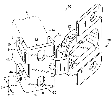
[0013] FIGURE 1 is a front perspective view of a cabinet hinge
having a mounting cup and a frame wing coupled thereto according to an
exemplary embodiment.
[0014] FIGURE 2 is a rear perspective view of the cabinet
hinge shown in FIGURE 1.
[0015] FIGURE 3 is a front perspective view of a cabinet hinge
having a mounting cup and a frame wing coupled thereto according to an
alternative embodiment.
[0016] FIGURE 4 is a top view of the cabinet hinge shown in
FIGURE 3.
[0017] FIGURE 5 is a front perspective view of a frame wing
according to an alternative embodiment.
[0018] FIGURE 6 is a front perspective view of an
interchangeable wrap of the frame wing shown in FIGURE 5.
[0019] FIGURE 7 is a top view of the frame wing shown in
FIGURE 5.
[0020] FIGURE 8 is a cross sectional view of the frame wing
shown taken across the line 8--8 in FIGURE 5.
DETAILED DESCRIPTION OF EXEMPLARY EMBODIMENTS
[0021] Referring to FIGURES 1-8, exemplary embodiments of
a hinge for mounting a cabinet door to a cabinet frame are shown. It should
be noted at the outset that the hinge can be used in any of a wide variety of
-4-
CA 02384919 2002-05-03
cabinet doors and other doors, including concealed and unconcealed hinge
arrangements known to those skilled in the art who may review the disclosure.
Referring to FIGURE 1, an exemplary embodiment of a hinge 10 is shown.
Hinge 10 is used to mount a cabinet door or door stile for selective pivotal
movement between an open position (depicted in FIGURE 1) and a closed
position with respect to a frame 40.
[0022] Hinge 10 includes a door wing 20 pivotally coupled to a
frame wing 30. Door wing 20 is shown as a hinge cup type door wing, and is
adapted to be mounted into and within a substantially cylindrical bore or
recess in a door. Hinge cup 22 may be adapted to fit into other bore
geometries, not limited to substantially cylindrical. Frame wing 30 is adapted
to be mounted to an edge 42 of frame 40 as depicted in FIGURE 1.
According to an exemplary embodiment,.the hinge arrangement shown,
having hinge cup 22 substantially embedded in a door, and having frame wing
30 mounted to edge 42 of frame 40, is an arrangement designed to conceal
the hinge from view when viewed from the front of a cabinet. This
arrangement is commonly known in the art as a "concealed" hinge.
[0023] Frame wing 30 includes base 32, front wrap 34, and
rear wrap 36. As depicted in FIGURE 1, base 32 is a substantially flat,
rectangular plate having a width, along horizontal axis X-X, substantially
corresponding to a width of frame 40. In an exemplary embodiment, base 32
has a width of approximately 0:6 inches, however, any base width may be
used depending on the thickness of the frame material to be used.
Furthermore, base 32 is oriented substantially perpendicular to rear frame
surface 43 and front frame surface 44.
[0024] As shown in FIGURE 1, base 32 includes mounting
slots 38, shown as oblong apertures in base 32. Mounting slots 38 are
configured to receive fasteners, such as but not limited to wood screw 56
(FIGURE 4). Wood screw 56 is inserted through mounting slot 38 and
screwed into frame 40, rigidly coupling frame wing 30 to frame 40. Once
attached to frame 40, frame wing 30 may be adjusted in a vertical direction
-5-
CA 02384919 2002-05-03
(shown as vertical axis Y-Y) by loosening wood screws 56 and sliding frame
wing 30 along axis Y-Y. The lftnit of vertical adjustment is bounded by the
length of mounting slot 38.
[0025] Frame wing 30 further includes rear wraps 36 and front
wraps 34. Rear wraps 36 and front wraps 34 extend substantially
perpendicular to base 32, and are substantially parallel with frame surface
43.
In an exemplary embodiment, front wrap 34 has a width, along vertical axis Y-
Y, of approximately 1.6 inches. Alternatively, front wrap 34 may have any
appropriate width. In an exemplary embodiment, front wrap 34 has a depth,
along depth axis Z-Z, of approximately 0.3 inches or anywhere in the range of
approximately 0.15 to 0.75 inches. Alternatively, front wrap 34 may have any
appropriate depth depending on the frame material. In an exemplary
embodiment, rear wrap 36 has a depth, along depth axis Z-Z, of
approximately 0.6 inches or anywhere in the range of approximately 0.4 to 1.0
inches. Alternatively, rear wrap 36 may have an appropriate depth to support
the frame material.
[0026] Shown in FIGURES 1-2, rear wrap 36 and front wrap
34 further include ribs 44. In an exemplary embodiment rib 44 is a raised
surface on inner surfaces 46 of rear wraps 36 and inner surfaces 48 of front
wraps 34. Raised surface 50 of rib 44 may be in the shape of a portion of a
cone. Alternatively, rib 44 may be any of a variety of textured surfaces,
including, but not limited to slotted, knurled, and/or other raised surfaces.
[0027] As discussed above, hinge 10 is used to mount a
cabinet door or door sitle for selective pivotal movement between an open
position and a closed position. In attaching hinge 10 to frame 40, frame wing
30 is slid over edge 42, located in a desired mounting position. As frame wing
30 is slid over edge 42, ribs 44 wedge into the front and rear of frame
surface
43 of cabinet frame 40. As ribs 44 wedge into frame surface 43, they operate
to grab frame 40, thereby assisting to hold hinge 10 in place prior to wood
screws 56 being inserted. Accordingly, an installer mounting frame wing 30 to
edge 42 of frame 40 could slide frame wing 30 onto edge 42. Frame wing 30
-6-
CA 02384919 2002-05-03
would be substantially held in position by ribs 44 even if the installer does
not
hold frame wing 30. Therefore, the installer may concentrate on positioning
and inserting screws 56.
[0028] As shown in FIGURES 3 and 4, but equally applicable
to alternative embodiments such as, but not limited to, those embodiments
depicted in FIGURES 1-2, and 5-8, to attach a frame wing 230 to a frame 240,
wood screw 256 is screwed into frame 240. As wood screw 256 is further
tightened into frame 240, the frame material tends to separate or be wedged
apart by wood screw 256. Because rear wrap 236 and front wrap 234 are
elongated and extend along surfaces 243 and 244 a significant distance, rear
wrap 236 and front wrap 234 serve to constrain the material of frame 240 from
expanding due to the wedging force of wood screw 256. Hinge 200 includes
a single flange rear wrap 236, as depicted in FIGURE 3 having ribs 237
formed on rear wrap 236. It should be noted that FIGURES 3 and 4 are
representative of the many and varied configurations of both rear wraps 236
and front wraps 234.
[0029] In an exemplary embodiment, frame wing 30 may be
configured to fit on a frame having a thickness in a range of 114 inch to 1
inch,
however, other frame material sizes may be used as well. Such materials
include, but are not limited to medium-density fiberboard (MDF), other
fiberboard, particle board, plywood, wood, etc.
[0030] Referring again to FIGURES 1 and 2, the oversized
front and rear wraps 36 and 34 offer several advantages. One such
advantage is front wrap 34 and rear wrap 36 help to prevent frame 40, which,
in an exemplary embodiment, is made from thin MDF or thin particle board,
from cracking, splitting, or breaking. Front wrap 34 and rear wrap 36 prevent
damage by applying a holding force to frame surface 43 when wood screws
56 are inserted into frame 40, thereby preventing frame 40 from expanding
due to the wedging force exerted by wood screws 56.
[0031] Furthermore, in addition to ribs 44, the oversized front
and rear wraps 34 and 36 increase the holding power of hinge 10 during
-7-
CA 02384919 2002-05-03
mounting. Because wraps 34 and 36 are elongated, more contact occurs
between wraps 34 and 36 than conventional devices. Such increased contact
area provides additional frictional interference adding to the holding power
of
frame wing 30.
[0032] Because of the oversized front and rear wraps 34 and
36 and ribs 44, the bend-back resistance of frame wing 30 and frame 40
combination is improved. As a door coupled to frame wing 30 is "over
opened" past a nominal point, wrap 34 will distribute the opening force over
surface 43, helping to resist breakage, failure, cracking, or splitting of the
material of frame 40. Further, ribs 44 help to prevent movement of wing 30
relative to frame 40, such that less pull out force is exerted on screw 56.
Accordingly, because of the unique design of frame wing 30, screw 56 is less
likely to be pulled out from edge 42 and the material of frame 40 is less
likely
to be damaged.
[0033] According to an alternative embodiment, depicted in
FIGURES 5-8, frame wing 130 may be a two piece design. Frame wing 130
includes insert 160 and interchangeable wrap 180.
[0034] Interchangeable wrap 180 includes base 132, front
wrap 134, and rear wrap 136. As shown in FIGURE 6, base 132 is a
substantially flat, rectangular portion having a width, along horizontal axis
X-X,
substantially corresponding to a width of frame. Base 132 is oriented
substantially perpendicular to frame surface 142.
[0035] Base 132 further includes aperture 182 located within
base 132. Aperture 182 is sized to receive insert 160 as will be discussed
below. Aperture 182 is substantially centered within base 132 but may be
alternatively located at any location along base 132. As shown in FIGURE 6,
interchangeable wrap 180 further includes wrap slots 138. Wrap slots 138 are
exemplary disposed substantially along a center-line axis of base 132, on an
outer edge of aperture 182.
[0036] Interchangeable wrap 180 further includes front wraps
134 and rear wraps 136. Rear wraps 136 and front wraps 134 extend
-8
CA 02384919 2002-05-03
substantially perpendicular to base 132, and are substantially parallel with
frame surface 143. In an exemplary embodiment, rear wrap 12, may be
configured with surface textures, such as, but not limited to ribs, which
serve
the same function as ribs 44, depicted in FIGURE 2.
[0037] Frame wing 130 further includes insert 160. Insert 160
includes plate 184, hinge arm 186, and pivots 188. Plate 184 is a
substantially flat, rectangular portion having a size substantially
corresponding
to the size of aperture 182. Plate 184 further includes insert slots 190
disposed substantially along a center-line axis of plate 184, on an outer edge
of plate 184. Plate 184 further includes wraps 192 which are substantially
perpendicular to plate 184, and are configured to correspond to the width of
interchangeable wrap 180. Alternatively, wraps 192 may be omitted.
[0038] Insert 160 and interchangeable wrap 180 are
assembled to form frame wing 130 which may be attached to frame 140.
Interchangeable wrap 180 is slid over edge 142, located in a desired
mounting position. As frame wing 130 is slid over edge 142, optional ribs
wedge into the front and rear of frame surface 143 of frame 140, thereby
assisting to hold frame wing 130 in place prior to assembly. Insert 160 is
then
fitted into aperture 182. Alternatively, because wraps 134 and 136 are
oversized and elongated, wraps 134 and 136 grip frame edge 142 by a
frictional interference fit and help to align plate 184 in place prior to
assembly.
When insert 160 is placed in aperture 182, insert slots 190 and wrap slots 138
are aligned to form fastener hole 194 (FIGURE 8). Fasteners, shown as
wood screws 156, are then attached to frame 140. Head 196 of wood screws
156 applies a force to both base 132 and plate 184, thereby preventing both
interchangeable wrap 180 and insert 160 from moving. Wood screws 156
may be used with an optional washer or may be washer head screws having
a large flange 197 which acts as a washer but is integrated into screw 156.
Frame wing 130 may be adjusted by loosening wood screws 156 and sliding
frame wing along axis Y-Y. The limit of adjustment is bounded by the length
of fastener hole 194.
-9
Eli I
CA 02384919 2002-05-03
[0039] The two piece design of frame wing 130 offers several
advantages. One such advantage is reducing the number of sized parts
required to assemble frame wing 130. In other words, plate '184 may be used
in conjunction with a variety of bases 132 which may be sized for different
frame widths. For example, the same insert 160 may be used for cabinet
frames utilizing frame material of a variety of different thicknesses. If, for
example, a cabinet frame is built using 3/ inch MDF and another is built using
Y2 inch MDF, the same insert 160 may be used for both cabinets, thereby
requiring only different frame wings 130. Also the frame wing dimensions
may be varied to optimize performance characteristics depending on the
frame material being used. Also, plate 184 may be easily interchanged with a
plate having a different hinge arm 186 configuration or hinge arm type.
[0040] It is also important to note that the construction and
arrangement of the elements of the hinge shown in the preferred and other
exemplary embodiments is illustrative only. Although only a few embodiments
of the present inventions have been described in detail in this disclosure,
those skilled in the art who review this disclosure will readily appreciate
that
many modifications are possible (e.g., variations in sizes, dimensions,
structures, shapes and proportions of the various elements, values of
parameters, mounting arrangements, use of materials, colors, orientations,
etc.) without materially departing from the novel teachings and advantages of
the subject matter recited in the claims. Accordingly, all such modifications
are intended to be included within the scope of the present invention as
defined in the appended claims. The order or sequence of any process or
method steps may be varied or re-sequenced according to alternative
embodiments. In the claims, any means-plus-function clause is intended to
cover the structures described herein as performing the recited function and
not only structural equivalents but also equivalent structures. Other
substitutions, modifications, changes and omissions may be made in the
-10-
CA 02384919 2002-05-03
design, operating conditions and arrangement of the preferred and other
exemplary embodiments without departing from the scope of the present
inventions as expressed in the appended claims.
-11-