Note : Les descriptions sont présentées dans la langue officielle dans laquelle elles ont été soumises.
CA 02385980 2002-03-27
WO 01/24730 PCT/USOO/27342
7
HEART VALVE CARRIER AND RINSE CAGE
Background of the Invention
Field of the Invention
The present invention relates to carriers for holding heart valves during
storage and transportation and, more particularly, to carriers for holding
heart valves
made from natural tissue (known as bioprosthetic heart valves).
Description of the Related Art
To minimize the possibility of damage to a relatively delicate medical device,
bioprosthetic heart valves are packaged in jars filled with preserving
solution for
shipping and storage prior to use in the operating theater. In doing so, the
valves are
stabilized to prevent the valves from striking the inside of the jar.
Prior to implantation in a patient, residual traces of the preserving solution
need to be washed from the valve. This washing is accomplished by first
removing
the valve from the jar and then rinsing the valve in a shower. Alternatively,
the valve
may be immersed and agitated in a bath. First, the medical personnel removes
the
valve from its jar by grasping a valve holder with a gloved hand. The valve
holder is
typically centrally located with respect to, and sutured to, the valve sewing
ring. A
surgical handle is then threaded into a socket provided in the valve holder.
The valve
is then rinsed in the bath or shower while being held at the end of the
handle. After
rinsing, the handle is used to position the valve in the appropriate
implantation site.
This conventional process leaves the valve susceptible to damage if the valve
strikes a
surface while being manipulated on the end of the surgical handle.
In addition to the susceptibility for damage to the valves in the operating
theater, the transportation of the valves to the operating theater also
introduces
problems. Heart valves are often shipped to customers, that is, hospitals, via
aircraft.
The valves, packed in jars as described above, are stored in the cargo hold of
the
aircraft during flight, which is a low-pressure and low-temperature
environment.
With conventional packaging approaches, there has been the possibility of
leakage of
the preserving fluid during transport in such environments, which is
undesirable.
With leakage, the integrity of the sterilization of the valve is suspect.
CA 02385980 2007-06-22
= ~
In view of the foregoing, it is apparent that there is still a need in the art
for a carrier for
heart valves that enables a medical practitioner to easily and safely remove
and rinse a valve, as
well as attached a surgical handle thereto. In addition, there is also a need
in the art for a carrier
for heart valves that does not leak during transportation, even in low-
pressure environments.
Summary of the Invention
The present invention provides a carrier for heart valves that overcomes the
disadvantages of conventional approaches to the packaging of heart valves. The
carrier of the
present invention enables a medical practitioner to first connect the surgical
handle to the valve
holder while the heart valve remains in its shipping carrier. In addition, the
carrier of the present
invention is configured to minimize or substantially eliminate leaking of pi-
eserving fluid during
transportation and storage.
Accoi-ding to an aspect thereof, the present invention provides a carriei- for
a heart valve,
the carrier comprising:
a rinse cage including a first engagement structure; and
a holder to which a heart valve is attachable, the holder including a second
engagement structure
complementary to the first engagement structure for releasably engaging with
the first
engagement structure, such that a heart valve attached to the holder is
disposed within the rinse
cage when the engagement structures are engaged, the rinse cage providing
structural protection
to the heart valve disposed within during a rinsing operation.
According to one aspect of the invention, a carrier for a heart valve may-
include a jar, a
rinse cage receivable within the jar, and a holder to which a heart valve is
attachable, for example,
by sewing apparatus. The rinse cage includes a first engagement structure, and
the holder
includes a second engagement structure complementary to the first engagement
structure for
releasably engaging therewith. The engagement structures are configured such
that when
engaged, a heart valve attached to the holder is disposed within the rinse
cage.
In accordance with a particular aspect the present invention provides a
carrier-and-heart
valve combination, the combination comprising:
a jar having a lid;
a rinse cage receivable within the jar, the rinse cage including a first
engagement structure
disposed thereon;
CA 02385980 2007-06-22
3
a holder including a sewing apparatus and a second engagement structure
complementary to the
first engagement structure for releasably engaging with the first engagement
structure;
a heart valve attached to the sewing apparatus of the holder; and
preserving fluid received within the jar;
the engagement structure being configured such that the heart valve is
suspended within the rinse
cage in the preserving fluid when the engagement structure are engaged.
One of the advantages of the carrier of the present invention is that a heart
valve attached
to the holder is protected not only when within the jar but also when removed
from the jar. More
specifically, when the holder is removed from the jar, the rinse cage with the
valve suspended
therein is also removed because the two components are engaged. Accordingly,
the heart valve
may be rinsed outside of the jar while still being received within and
protected by the rinse cage.
To facilitate the removal of the holder-and-i-inse cage combination, the
holder preferably
has a socket for engaging with a surgical handle. A medical practitioner may
attach a surgical
handle to the holder to remove the valve from the jar while the valve is still
received within the
rinse cage in the jar. Accordingly, the practitioner does not need to manually
remove and hold
the valve to attach a handle.
To facilitate the engagement of the surgical handle, the carrier may include a
stop which
is configured to limit rotation of the holder relative to the rinse cage, and
locking apparatus which is configured to limit rotation of the rinse cage
relative to the jar.
Accordingly, as a surgical handle is tightened into the socket, frictional
forces cause the holder to
rotate. However, the stop limits the rotation by engaging with the rinse cage.
As the handle is
further tightened, frictional forces cause the rinse cage to rotate, which
rotation is limited by the
locking apparatus. Accordingly, a medical practitioner is able to engage a
surgical handle
securely and firmly without needing to manually remove the valve from the jar.
As mentioned above, according to anothei- aspect of the invention, the calTier
may include a lid
attachable to the jar. A lid may have-a gasket that is held rotatable relative
to the lid with a flange.
To form a seal with integrity, a top surface of the jar may be tapei-ed to
define an apex. When the
lid is attached to the jar, the apex contacts and compresses the gasket as the
lid is tightened,
without the gasket rotating responsively with the lid. To further increase the
integrity of the seal,
the flange may include a vent for allowing gases between the gasket and the
lid to escape during
sterilization processes of the carrier.
CA 02385980 2007-06-22
3a
In accordance with a further aspect the present invention provides a method
for removing a heart
valve from a carrier, the method comprising:
providing a sui-gical handle with threading;
providing a carn-ier with a heart valve including:
a jar having a lid;
a rinse cage receivable within the jar, the rinse cage including a first
engagement
structure disposed thereon ;
a holder including a socket with threading complementary to that of the
surgical handle, a
sewing apparatus; a second engagement structure complementary to the first
engagement
structure for releasably engaging with the first engagement structure, and a
stop for
preventing rotation of the holder relative to the rinse cage;
a locking apparatus disposed on the rinse cage and the jar for preventing
rotation of the
rinse cage relative to the jar;
a heart valve attached to the sewing apparatus of the holder; and
preserving fluid received within the jar;
and
engaging the surgical handle with the socket.
Other aspects, features, and advantages of the present invention will become
apparent to
those skilled in the art from a consideration of the following detailed
description taken in
conjunction with the accompanying drawings which illustrate, by way of
example, the
principles of the present invention in the context of a carrier for heart
valves, but which
are equally relevant to other carriers in which items are stored or
transported.
CA 02385980 2007-06-22
3b
BRIEF DESCRIPTION OF THE SEVERAL VIEWS OF THE DRAWINGS
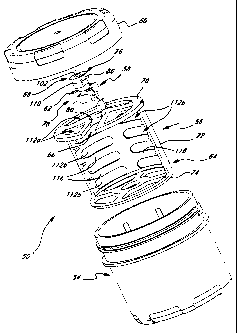
FIG. 1 is an exploded perspective view of an exemplary carrier for holding a
heart valve
in accordance with the present invention;
FIG. 2 is a perspective view of the carrier of the invention, particularly
illustrating the carrier
holding a heart valve;
FIG. 3 is a plan view of a portion of a rinse cage of the carrier,
particularly illustrating a holder
(shown in phantom line) engaged with the rinse cage;
FIG. 4 is a vertical cross-sectional view of the rinse cage of the invention
taken along line 4--4 of
CA 02385980 2002-03-27
WO 01/24730 PCTIUSOO/27342
4
FIG. 5 is a cross-sectional view of exemplary engagement apparatus of the
invention for engaging the holder with the rinse cage;
FIG. 6 is a cross-sectional view of exemplary rotation-limiting apparatus of
the invention for limiting the rotation of the holder when engaged with the
rinse cage;
FIG. 7 is a horizontal cross-sectional view of the rinse cage received within
a
jar of the carrier taken along line 7-7 of FIG. 2, particularly illustrating
locking
apparatus for limiting the rotation of the rinse cage within the jar;
FIG. 8 is a cross-sectional view of the rinse cage received within the jar,
particularly the locking apparatus, taken along line 8-8 of FIG. 7;
FIG. 9 is a cross-sectional view of the jar and a lid of the carrier of the
present
invention; and
FIG. 10 is an enlarged cross-sectional view of the lid attached to the jar,
particularly illustrating a seal formed therebetween.
Detailed Description of the Invention
Referring more particularly to the drawings, a carrier 50 for holding a
bioprosthetic heart valve 52 is shown in FIGS. 1 and 2 in an exemplary
embodiment
according to the present invention. Exemplary carrier 50 generally includes a
jar 54, a
rinse cage 56, and a holder 58. The jar 54 is sealable with a lid 60. The
rinse cage 56
is receivable within the jar 54, as shown in FIG. 2. The holder 58 is
releasably
engageable with the rinse cage 56 and has sewing apparatus 62 to which a valve
is
releasably attachable. Desirably, the sewing apparatus 62 comprises eye-holes
and\or
notches to which the sutures may be fastened.
Exemplary carrier 50 of the present invention enables a medical practitioner
to
remove the heart valve 52 from the jar 54 without having to manually grasp the
valve
52, the rinse cage 56, the holder 58, or any other element of the carrier
except the jar.
In addition, exemplary carrier 50 is configured to ensure a leak-proof seal
between the
jar 54 and the lid 60, even while in low-pressure environments such as cargo
holds in
airplanes. These and additional features of the present invention are
discussed in
detail below.
Exemplary rinse cage 56 includes a frame 64 with first engagement structure
66 disposed thereon. In addition to the sewing apparatus 62, exemplary holder
58
includes second engagement structure 68 complementary to the first engagement
CA 02385980 2002-03-27
WO 01/24730 PCT/USOO/27342
structure 66 of the rinse cage 56 so that the engagement structures may be
releasably
coupled. More particularly and as shown in FIG. 2, when the engagement
structures
66 and 68 are engaged, the heart valve 52 attached to the sewing apparatus 62
of the
holder 58 is disposed within the rinse cage 56.
5 With reference to FIGS. 3 and 4, an exemplary embodiment of the
engagement structures 66 and 68 is shown in which the second engagement
structure
68 of the holder 58 engages with the first engagement structure 66 of the
rinse cage 56
in a sliding motion. More particularly, and with reference also to FIG. 1,
exemplary
rinse cage 56 has a planar, circular, top member 70, a tubular side member 72,
and a
planar, circular bottom member 74, and exemplary holder 58 has a top portion
76 and
a bottom portion 78. Desirably, and as described below, top member 70, side
member
72, and bottom member 74 are all perforated to permit fluid flow therethrough.
First
engagement structure 66 is disposed on the top member 70 of the rinse cage 56
and
may include a channel 80 formed therein, extending from an outer edge 82
thereof to
an inner portion 84 thereof. Exemplary second engagement structure 68 is
disposed
on the top portion 76 of the holder 58 and may include a groove 86 between top
and
bottom portions 76, 78 which is slidable within the channel 80.
With additional reference to FIG. 5, when the groove 86 is disposed within the
channe180, a upper lip 88 of exemplary second engagement structure 68 rests
upon a
top surface 90 of the top member 70 of the rinse cage 56, thereby suspending
the
bottom portion 78 below the top member 70 and within the rinse cage 56, as
particularly shown in FIG. 4. To engage, the groove 86 is positioned at the
outer edge
82 of the channel 80, and the holder 58 is slid inward; to disengage, the
holder 58 is
slid outward, which sliding motion is shown by arrows A in FIGS. 3 and 4.
As particularly shown in FIG. 5, the channel 80 of exemplary first engagement
structure 66 may be configured to form a pair of opposing rails 92 in a spaced
relationship across the channel 80. Further, exemplary second engagement
structure
68 may also have a lower lip 94 disposed in a spaced relationship with the
upper lip
88 across the groove 86, so that the groove 86 acts as a race in which the
rails 92 are
slidably receivable. In this particularly exemplary embodiment, the groove 86
has a
thickness that is greater than or equal to a thickness of the rails 92,
preferably slightly
greater than, to provide a secure engagement therebetween.
CA 02385980 2002-03-27
WO 01/24730 PCT/USOO/27342
6
With particular reference to FIG. 3, the channe180 of exemplary first
engagement structure 66 has a width w that preferably decreases from the outer
edge
82 (i.e., width wo) to the inner portion 84 (i.e., width w;). Accordingly,
exemplary
channe180 has a neck 96 defined at the inner portion 84 thereof. In addition,
exemplary channe180 may have a seat 98 formed at the inner portion 84 thereof.
With reference to FIG. 6, exemplary second engagement structure 68 of the
holder 58
has a central post 100 around which the groove 86 is formed. The seat 98 has a
diameter d,s (FIG. 3), and the post 100 has a diameter dp (FIG. 6).
According to the exemplary embodiment of the invention shown in the
drawings, diameter dS of the seat 98 is greater than to diameter dp of the
post 100, and
diameter dp of the post 100 is greater than or equal to width w; of the neck
96 such
that the post 100 is urgeable through the neck 96, thereby "snapping" into the
seat 98.
When the post 100 is received within the seat 98, the upper lip 88 is
positioned upon
the portion of the top surface 90 surrounding the seat 98, thereby suspending
the
bottom portion 78 of the holder 58, as well as a heart valve attached to the
sewing
apparatus 62, between the top member 70 and the bottom member 74 of the rinse
cage
56. To disengage, the post 100 is urged outward through the neck 96, thereby
snapping out of the seat 98. The suspension of the heart valve 52 within the
confines
of the rinse cage 56 prevents the valve from contacting any surface (i.e., the
frame 64
and the jar 54) during shipping and handling, thereby preventing any damage to
the
valve.
With reference to FIGS. 1 and 3-5, exemplary holder 58 may include a socket
102 disposed in the top portion 76 thereof for engaging with a surgical handle
104.
The socket 102 is disposed on the holder 58 such that the socket 102 is above
the
frame 64 when the engagement structures 66 and 68 are engaged, as particularly
shown in FIG. 4. For example, the socket 102 may extend downward through the
post 100, as shown in FIGS. 4 and 5. The socket 102 may have inner threading
106
for engaging with complementary threading 108 on the surgical handle 104. When
the engagement structures 66 and 68 are engaged, for example, when the post
100 is
received in the seat 98, the surgical handle 104 may be engaged with the
socket 102 to
maneuver the holder 58 in and out of the rinse cage 56.
CA 02385980 2002-03-27
WO 01/24730 PCT/USOO/27342
7
When engaging with the holder 58, the handle 104 is rotated into the socket
102. Because of frictional forces on the respective threading 106 and 108 of
each of
these elements, the holder 58 may rotate responsively, particularly as the
engagement
begins to tighten. To facilitate a secure engagement of the handle 104 with
the socket
102, rotation-limiting apparatus may be provided to limit rotation of at least
the socket
102, if not the holder 58 as a whole, allowing the handle 104 to be forcibly
rotated
into the socket 102. The rotation-limiting apparatus may include a stop 110
that is
configured to limit rotation of the post 100 and, according, the socket 102
and the
holder 58 when the post 100 is received in the seat 98. More specifically, as
seen in
FIG. 6, exemplary stop 110 projects outward from the post 100 such that when
the
post 100 is received within the seat 98, the stop 110 projects through the
neck 96 and
into the channe180, as particularly shown in FIG. 3 in phantom line. Exemplary
stop
110 may have a width that is less than or equal to width w; at neck 96 so that
the neck
941imits rotation of the stop 110 and, accordingly, the holder 58. Additional
advantages of the rotation-limiting apparatus will be discussed in detail
below.
With reference to FIGS. 1 and 2, at least one of the members (i.e., the top
member 70, the side member 72, and/or the bottom member 74) of the frame 64 of
the
rinse cage 56 has at least one opening 112 formed therein. The openings 112
formed
in the top member 70 of the frame 64 are specifically indicated by reference
numeral
112a; the openings 112 formed in the side member 72, by reference numeral
112b;
and the openings in the bottom member 74, by reference numeral 112c. The
openings
112 in the frame 64 allow fluid 114 contained in the jar 54 for preserving the
valve 52
to flow freely through the rinse cage 56. In addition, the openings 112 in the
frame 64
allow the valve 52 to be rinsed in a shower or immersed in a bath to remove
residual
traces of the fluid 114 when the rinse cage 56 and the holder 58 are removed
from the
jar 54 with the surgical handle 104. After the valve 52 has been rinsed, the
holder 58
may be disengaged from the rinse cage 56 and positioned at a surgical site.
Referencing FIGS. 1 and 4, openings 112b formed in the side member 72 of
the frame 64 may be formed as a plurality of substantially circumferential
openings so
that a plurality of circumferential ribs 116 are defined. The ribs 116 provide
not only
support to the frame 64 but also protection to the valve 52 attached to the
holder 58
when received within the jar 54 and when the engagement structures 66 and 68
are
CA 02385980 2002-03-27
WO 01/24730 PCTIUSOO/27342
8
engaged. More specifically, when the engaged rinse cage-and-holder combination
is
removed from the jar 54 with the surgical handle 104, the valve 52 attached to
the
holder 56 is protected not only from the top and bottom from the respective
members
70 and 74 of the frame 64 but also about a substantial extent laterally from
the side
member 72, as particularly shown in FIG. 4. For example, exemplary rinse cage
56
may be configured so that the side member 72 extends through an approximately
180-
degree arc. Accordingly, the rinse cage-and-holder combination may be moved
about, for example, during rinsing, prior to removing the holder-and-valve
combination from the rinse cage 56, with a substantial degree of protection
for the
valve 52. The semi-cylindrical configuration of the frame 64 of the rinse cage
56
provides a correspondingly semi-cylindrical opening 116 through which the
valve 52
passes when the holder 56 is engaged and disengaged with the rinse cage 56. In
this
respect, the channe180 extends from inner portion 84 of top member 70 towards
open
side of side member 72.
With additional reference to FIGS. 7 and 8, exemplary carrier 50 of the
present invention may also include locking structure for limiting the rotation
of the
rinse cage 56 within the jar 54. Generally, the locking structure of the
present
invention may include a receptacle disposed on the rinse cage 56 and a
protrusion 118
disposed on the jar 54, with the protrusion 118 being receivable within the
receptacle.
According to an exemplary embodiment of the invention, each of the openings
112c
formed in the bottom member 74 of the frame 64 may serve as a receptacle for
receiving a respective protrusion 118 of a plurality of protrusions disposed
on a
bottom 120 of the jar 54. The openings 112c define a plurality of spokes 122
therebetween. When engaged, the protrusions 118 respectively project upward
into
the openings 112c and are able to contact a respective spoke 122 to prevent
rotation of
the rinse cage 56 relative to the jar 54. As particularly shown in FIG. 7, the
protrusions 118 may be configured to complement the shape of the openings
112c; for
example, in the exemplary embodiment shown, the protrusions 118 and the
openings
112c are substantially arcuate.
One of the advantages of the rotation-limiting apparatus (i.e., the stop 110)
and the locking apparatus (i.e., the protrusions 118 and the openings 112c),
as well as
the engagement structures 66 and 68, of the present invention is that a
medical
CA 02385980 2002-03-27
WO 01/24730 PCT/USOO/27342
9
practitioner may not only engage the surgical handle 104 with the socket 102
in a
secure manner but may also remove the combination of the heart valve 52, the
holder
58, and the rinse cage 56 in a quick and easy manner. More specifically, to
remove
the heart valve 52 from the jar 54, the surgical handle 104 is engaged with
the socket
102 by rotating. When the frictional forces of the threading 106 and 108 cause
the
holder 58 to rotating, the stop 110 engages the channel 80 to prevent further
rotation
of the holder 58. As the engagement of the handle 104 with the socket 102
becomes
more secure, the frictional forces of the threading 106 and 108 cause the
rinse cage 56
to rotate. However, rotation of the rinse cage 56 is limited or prevented by
the
protrusions 118 engaging with the spokes 122. Accordingly, holding the jar 54
in one
hand and the surgical handle 104 in the other, a medical practitioner may
firmly
engage the surgical handle 104 with the holder 58 without putting pressure on,
or
otherwise handling, the heart valve.
Referencing FIG. 9, the jar 54 and the lid 60 are shown in more detail. The
lid
60 has threading 124 for engaging with complementary threading 126 of the jar
54.
In addition, exemplary lid 60 includes a gasket 128 disposed against an inner
top
surface 130 thereof and retained by a flange 132. According to the present
invention,
exemplary gasket 128 is not fixed to the lid 60 but is rather able to move or
rotate
independently of the lid 60. The rotatable gasket 128 facilitates the
formation of a
leak-proof seal between the lid 60 and the jar 54. To further facilitate the
formation
of a leak-proof seal, exemplary jar 54 may include a pointed top surface or
apex 134.
More specifically, with reference to FIG. 10, when engaging the lid 60 with
the jar 54, the apex 134 of the jar 54 comes into contact with the gasket 128.
With
continued tightening of the lid 60, the apex 134 compresses the gasket 128 and
concentrates the sealing force at a relatively small contact area, thereby
forming a
substantially leak-proof the seal between the gasket 128 and the apex 134. The
apex
134 is preferably rounded to reduce the possibility of damage to the gasket
128.
Referencing FIG. 9, exemplary lid 60 may include a vent 136 formed in the
flange 132. Prior to receiving a heart valve, the carrier 50 is sterilized.
The vent 136
allows gases between the gasket 128 and the inner surface 130 of the lid 60,
for
example, in an air space 138, to escape during sterilization processes. The
efficient
removal of gases between the gasket 128 and the lid 60 further improves the
seal
CA 02385980 2002-03-27
WO 01/24730 PCT/US00/27342
between the jar 54 (i.e., the apex 134) and the gasket 128, particularly when
the
carrier 50 is being transported in a low-pressure and low-temperature
environment,
for example, a cargo hold of an airplane. As gas disposed between the gasket
128 and
the lid 60 is able to vent during the sterilization process, the seal made
between the jar
5 54 and the gasket 128 is made at low pressure and, accordingly, will not be
adversely
affected when the carrier 50 is transported at in a low-pressure environment
and then
stored in an environment with relatively high pressure and temperature.
A further significant advantage of the present heart valve carrier is the
ability
to unify the handling process for a number of different heart valves. That is,
the
to present carrier is capable of receiving a number of different types of
heart valves, as
long as the engagement structure on the valve holder matches the engagement
structure on the rinse cage. So, for example, a number of heart valves can be
mounted
on the holder shown and described, which attaches via sutures to the cloth
sewing
ring. Other valves may be attached to a different holder that includes the
second
engagement structure 68 shown best in Figure 1. With such flexibility, the
steps of
handling, shipping, receiving, handle attaching and rinsing are identical with
all the
heart valves.
Those skilled in the art will understand that the present invention is not
limited to
the specifically illustrated and described embodiments above. The scope of the
present
invention is determined by the terms of the appended claims and their legal
equivalents,
rather than by the examples described above.