Sélection de la langue

Search

Sommaire du brevet 2396532 

Énoncé de désistement de responsabilité concernant l'information provenant de tiers

Une partie des informations de ce site Web a été fournie par des sources externes. Le gouvernement du Canada n'assume aucune responsabilité concernant la précision, l'actualité ou la fiabilité des informations fournies par les sources externes. Les utilisateurs qui désirent employer cette information devraient consulter directement la source des informations. Le contenu fourni par les sources externes n'est pas assujetti aux exigences sur les langues officielles, la protection des renseignements personnels et l'accessibilité.

Disponibilité de l'Abrégé et des Revendications

L'apparition de différences dans le texte et l'image des Revendications et de l'Abrégé dépend du moment auquel le document est publié. Les textes des Revendications et de l'Abrégé sont affichés :

  • lorsque la demande peut être examinée par le public;
  • lorsque le brevet est émis (délivrance).
(12) Demande de brevet: (11) CA 2396532
(54) Titre français: MOTEUR DE FORAGE A PALETTES ET A ROULEAUX A TREPAN OU RACCORD COUDE LONG
(54) Titre anglais: LONG GAUGE ROLLER VANE DRILLING MOTOR
Statut: Réputée abandonnée et au-delà du délai pour le rétablissement - en attente de la réponse à l’avis de communication rejetée
Données bibliographiques
Abrégés

Abrégé français

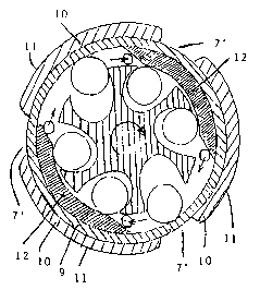
L'invention concerne un moteur de forage à palettes et à rouleaux à une enveloppe pour le forage fond de trou horizontal et dévié. L'enveloppe (9) du moteur selon l'invention comporte sur sa circonférence un ou plusieurs éléments courbes (10) de façon à créer une nouvelle surface externe circulaire plus grande (11) ayant un diamètre à peu près égal à celui du trépan en dessous, un ou plusieurs évidements longitudinaux (7') étant ménagés pour la remontée du fluide de forage à la surface. Les éléments courbes (10) peuvent commencer en dessous de l'extrémité inférieure du moteur ou à son extrémité inférieure et peuvent ou non s'étendre jusqu'à son extrémité supérieure.


Abrégé anglais


A single-jacket roller vane drilling motor for downhole deviated and
horizontal drilling has its jacket (9) provided at its circumgerence with one
or more curved members (10) in such a way that a new, larger circular outside
surface (11) is created with a diameter approximately equal to that of the
drill bit below, and whereby one or more longitudinal recesses (7') are
created for passage of the drilling fluid back to the surface. The curved
members (10) may start below the lower end of the motor or at its lower end
and may or may not extend to its upper end.

Revendications

Note : Les revendications sont présentées dans la langue officielle dans laquelle elles ont été soumises.


claims.
1. A system for downhole drilling and coring, said system
comprising a roller vane motor for driving a drill bit, said motor
having a single jacket with a lower end and an upper end and being
embodied such that all drilling fluid passes inside said jacket to
the drill bit, said system further comprising a bent sub connected
to the upper end of the motor,
the jacket being provided with outwardly projecting curved members
forming recesses therebetween for the passage of return drilling
fluid, the curved members creating a circular surface having a
diameter approximately equal to that of the drill bit,
characterized in that the curved members as well as the recesses
therebetween each extend in longitudinal direction over the full
length of the jacket of the motor.
2. A system according to claim 1, wherein the curved members are
extended to beneath the lower end of the jacket to near the drill
bit.
3. A system according to claim 1 or 2, wherein the motor has wing
deflector cams forming part of the jacket, a longitudinal recess
being provided at the outer surface of the jacket opposite the wing
deflector cam, and wherein the jacket above and below the wing
deflector cams has an internal diameter approximately equal to that
of the wing deflector cams.
4. A method for drilling and coring curved and horizontal borehole
sections, wherein use is made of a system according to one or more
of the preceding claims and wherein the bent sub is connected to a
non-rotating drill pipe.
5. A roller vane motor for driving a drill bit, said motor having
a single jacket with a lower end and an upper end and being embodied
such that all drilling fluid passes inside said jacket to the drill

2
bit, the jacket being provided with outwardly projecting curved
members forming recesses therebetween for the passage of return
drilling fluid, the curved members creating a circular surface
having a diameter approximately equal to that of the drill bit,
characterized in that the curved members as well as the recesses
therebetween each extend in longitudinal direction of the jacket of
the motor, and in that the motor has wing deflector cams forming
part of the jacket, each longitudinal recess being provided at the
outer surface of the jacket opposite a wing deflector cam, and
wherein the jacket above and below the wing deflector cams has an
internal diameter approximately equal to that of the wing deflector
cams.

Description

Note : Les descriptions sont présentées dans la langue officielle dans laquelle elles ont été soumises.


CA 02396532 2002-07-05
WO 01/49964 PCT/NL00/00010
1
LONG GAUGE ROLLER VANE DRI LI~ 1 1(; ~10TC'=
The invention relates to a drilling motor azd a system and method
for drilling curved boreholes.
To drill curved boreholes, it is known to use a system as shown in fig. 1
of the drawing. A downhole drilling motor 1 is connected at its lower end
to a drill bit 2 and at its upper end by means of a bent sub 3 with
bend angle o( to non-rotating drillpipe 4. Drilling fluid is pumped
down the drillpipe 4 to drive the drilling motor 1 that rotates the
drill bit 2. The drilling fluid passes throughthe drill bit 2 to cool
and lubricate it and to carry the drill cuttings to the surface
through the annular space between the drillpipe 4 and the borehole
wall 5. The curvature of the borehole is obtained with the bent sub
3, that causes the drillpipe 4 not only to exert a longitudinal
force on the drill bit 2, but also a sideways force. To obtain a
curvature in the desired direction at the start of the curved bore-
hole section, the bent sub 3 must be orientated in the desired
direction.
CCn'JentlO :311 y , the d0~.~':1~'1C1 a dr1111no mOtOr 1 1S a pOSltlVe
dlST~~.aCP-
ment motor (PDM) based on the moineau principle: A rotor with a single
external helix rotates inside a stator containing an internal double
elastomeric helix. This arrangement creates a se~ies of cavities.
~ihen drilling fluid is pumped down the space between rotor and stator,
these cavities progress downward, turning t:~e ra-or.
A problem with this system of curved drilling is that, when using the
rather long downhole drilling motors of the moinaau type, the curved
section is somewhat spiral-shaped, which slows town the drilling pro-
cess. To solve this problem, attempts have been jade to stabilize the
drill bit by placing a long gauge sub between t7= drill bit and the
drilling motor, or by using long gauge d:il'~ bi:=. Both methods
failed, because it proved impossible to start or retain a borehole of
the desired curvature under these circumstances.
The problem of borehole spiraling in curved bore-~oles can be eliminated
or minimized by using systems as shown in fig. 2 of the drawing. A shorter
downhole positive displacement drilling motor 1' is directly attached to
a long gauge bit 2' (fig. 2a) or is attached to a short gauge bit 2
by means of a long gauge sub 6, at its circumference equipped with

CA 02396532 2002-07-05
WO 01/49964 PCT/NL00/00010
2
one or more longitudinal recesses 7 for passage of the return drilling
fluid hack to the surface (fig. 2b). These short downhole positive
displacement drilling motors are preferably of the roller vane type with
single jacket, with all the drilling fluid passing inside this jacket
to the drill bit, as described in lJ0 99/20904 (PCT/NL 98/00598), which
give a similar performance as the much longer moineau drilling motors.
As a result, a curved borehole can be drilled with the same radius of
curvature with a much smaller bend angle in the bent sub 3. In that
way, the problem of too much sideways force on the drill bit is elimi-
nated and little or no spiraling occurs in the curved borehole section.
The present invention provides an adapted even shorter downhole positive
displacement roller vane drilling motor with single jacket for drilling
borehole sections of the same radius of curvature with a smaller bend
angle in the bent sub above the motor, or for drilling borehole sections
of smaller radius of curvature kith the same bend angle in the bent sub
above the motor. To this end, the motor is adapted to take over the
stabilizing function of the long gauge bit or the long gauge sub shown
in fig. 2.
The prese.~.t inventi on tail 1 be elucidated bel ow in more detail ::ith
reference to the drawing, showing in:
fig. 3 transverse sectional views from above of embodiments of a
short downhole positive displacement drilling motor of the present
invention;
fig. 4 systems for drilling curved borehole sections in which short
downhole drilling motors of the present invention are used;
fig. 5 longitudinal cross sections of embodiments of a short down-
hole positive displacement drilling motor of the present invention.
Referring to fig. 3a, a single-jacket roller vane drilling motor as
described in w0 99/20904 (PCT/IJL 98/00598) has its jacket 9 provided at
its circumference with one or more curved members 10 in such a way
that a new, larger circular outside surface 11 is created with a
diameter approximatel4' equal to t';at of the drill bit 2 below, and where-
by one or more longitudinal recesses 7' are created for passage of the
drilling fluid back to the surface. The curved members 10 may start
below the lower end of. the motor or at its lower end and may or may
wot extend to its upper end. if the curved members 10 start below the
lower end of the motoa, t-lie ,jacket c1 of the motor, and therefore: t-I~e
recesses i' may also i~c~ extended I~elow the lower encl of the motor.

CA 02396532 2002-07-05
WO 01/49964 PCT/NL00/00010
3
In the embodiment shown in fig. 3b, the recesses 7' are created in the
motor jacket 9 itself, this jacket being of increased thickness. Here
also, the increased thickness with recesses 7' may start at or below
the lower end of the motor and may or may not extend to its upper end.
In the embodiment shown in fig. 3c, the wing deflector cams 12 of the'
motor are part of the motor jacket 9 and the recesses 7' are created in
the motor jacket 9, opposite these wing deflector cams 12. In this em-
bodiment, the recesses 7' must run the length of the motor, so that the
motor jacket 9 above and below the wing deflector cams 12 must have an
1Q' internal diameter approximately equal to that of the wing deflector
cams 12.
Fig. 4 shows three schematic longitudinal side views of systems for dril-
ling curved borehole sections in which motors of the present invention
are used.
In fig. 4a a short downhole drilling motor 1" of the present invention is
attached at its lower end to a drill bit 2 and at its upper end to a bent
sub 3 and further to non-rotating drillpipe 4. The long gauge part of the
motor with recesses 7' for the drilling fluid runs the full length of tr_e
motor.
In fig. 4b a short downhole drilling motor 1" of the present invention is
attached at its lower end to a drill bit 2 and at its upper end to a bent
sub 3 and further to non-rotating drillpipe 4. The long gauge part of the
motor with recesses 7' for the drilling fluid extends only partly up the
motor.
In fig. 4c a short downhole drilling motor 1" of the present invention is
attached at its lower end to a drill bit 2 and at its upper end to a bent
sub 3 and further to non-rotating drillpipe 4. The long gauge part of the
motor is extended below the motor body to near the cutting edge of the
drill bit 2 by extending the curved members 10. This improves the stabi-
lizing effect of the motor-bit combination.
Fig. 4 also illustrates that the system from bit bottom to the bent sub
above the short downhole drilling motor according to the present invention
is much shorter than known stabilized systems shown in fig. 2. Firstly,
(part of) the motor takes over the stabilizing function of the long gauge
section of the drill bit or the long gauge sub. Secondly, the long gauge
motor, in particular the embodiment shown in fib. 3c, has a substantially
J-anger inside diameter. As a result, for the same G-~~wer input and output,
it is significantly shorter.

CA 02396532 2002-07-05
WO 01/49964 PCT/NL00/00010
4
A further reduction in the length of the motor-bit combination is
possible by eliminating the open space between the cutting edge of
the drill bit and the motor. This can be achieved by incorporating
the drive sub of the drill bit in the lower part of the motor as
shown in fig. S.
Fig. 5a shows a longitudinal section of the lower part of a short
roller vane drilling motor with single jacket 9 and curved members
outside the lower part of the motor, according to the present
invention. The rotor shaft 13 passes through the sealing member 14,
10 and the drive sub 15 for attaching the drill bit 2 is attached to
the rotor shaft 13 below the sealing member 14.
In fig. 5b the drive sub 15 is attached to the rotor shaft 13 below
the lower bearing housing 16 of the motor, the drive sub 15 and the
sealing member 14 forming one unit.
The drilling motors according to the present invention may not only
be used for deviated drilling but also for horizontal drilling and
for coring purposes. The invention'includes therefore within its
scope systems for drilling and coring deviated and horizontal bore-
hole sections in which drilling motors of the present invention
are used, as well as methods for drilling and coring deviated and
horizontal borehole sections using a drilling motor of the present
invention.

Dessin représentatif
Une figure unique qui représente un dessin illustrant l'invention.
États administratifs

2024-08-01 : Dans le cadre de la transition vers les Brevets de nouvelle génération (BNG), la base de données sur les brevets canadiens (BDBC) contient désormais un Historique d'événement plus détaillé, qui reproduit le Journal des événements de notre nouvelle solution interne.

Veuillez noter que les événements débutant par « Inactive : » se réfèrent à des événements qui ne sont plus utilisés dans notre nouvelle solution interne.

Pour une meilleure compréhension de l'état de la demande ou brevet qui figure sur cette page, la rubrique Mise en garde , et les descriptions de Brevet , Historique d'événement , Taxes périodiques et Historique des paiements devraient être consultées.

Historique d'événement

Description Date
Inactive : CIB de MCD 2006-03-12
Demande non rétablie avant l'échéance 2004-01-06
Le délai pour l'annulation est expiré 2004-01-06
Réputée abandonnée - omission de répondre à un avis sur les taxes pour le maintien en état 2003-01-06
Inactive : Page couverture publiée 2002-12-02
Lettre envoyée 2002-11-28
Inactive : Notice - Entrée phase nat. - Pas de RE 2002-11-28
Demande reçue - PCT 2002-09-13
Exigences pour l'entrée dans la phase nationale - jugée conforme 2002-07-05
Demande publiée (accessible au public) 2001-07-12

Historique d'abandonnement

Date d'abandonnement Raison Date de rétablissement
2003-01-06

Taxes périodiques

Le dernier paiement a été reçu le 2002-07-05

Avis : Si le paiement en totalité n'a pas été reçu au plus tard à la date indiquée, une taxe supplémentaire peut être imposée, soit une des taxes suivantes :

  • taxe de rétablissement ;
  • taxe pour paiement en souffrance ; ou
  • taxe additionnelle pour le renversement d'une péremption réputée.

Les taxes sur les brevets sont ajustées au 1er janvier de chaque année. Les montants ci-dessus sont les montants actuels s'ils sont reçus au plus tard le 31 décembre de l'année en cours.
Veuillez vous référer à la page web des taxes sur les brevets de l'OPIC pour voir tous les montants actuels des taxes.

Historique des taxes

Type de taxes Anniversaire Échéance Date payée
Taxe nationale de base - générale 2002-07-05
TM (demande, 2e anniv.) - générale 02 2002-01-07 2002-07-05
Enregistrement d'un document 2002-07-05
Titulaires au dossier

Les titulaires actuels et antérieures au dossier sont affichés en ordre alphabétique.

Titulaires actuels au dossier
ULTIDRILL B.V.
Titulaires antérieures au dossier
ARNOLD WILLEM JOSEPHUS GRUPPING
Les propriétaires antérieurs qui ne figurent pas dans la liste des « Propriétaires au dossier » apparaîtront dans d'autres documents au dossier.
Documents

Pour visionner les fichiers sélectionnés, entrer le code reCAPTCHA :


Pour visualiser une image, cliquer sur un lien dans la colonne description du document. Pour télécharger l'image (les images), cliquer l'une ou plusieurs cases à cocher dans la première colonne et ensuite cliquer sur le bouton "Télécharger sélection en format PDF (archive Zip)" ou le bouton "Télécharger sélection (en un fichier PDF fusionné)".

Liste des documents de brevet publiés et non publiés sur la BDBC .

Si vous avez des difficultés à accéder au contenu, veuillez communiquer avec le Centre de services à la clientèle au 1-866-997-1936, ou envoyer un courriel au Centre de service à la clientèle de l'OPIC.


Description du
Document 
Date
(aaaa-mm-jj) 
Nombre de pages   Taille de l'image (Ko) 
Dessin représentatif 2002-07-04 1 15
Dessins 2002-07-04 3 97
Description 2002-07-04 4 176
Abrégé 2002-07-04 1 63
Revendications 2002-07-04 2 70
Avis d'entree dans la phase nationale 2002-11-27 1 189
Courtoisie - Certificat d'enregistrement (document(s) connexe(s)) 2002-11-27 1 106
Courtoisie - Lettre d'abandon (taxe de maintien en état) 2003-02-02 1 176
PCT 2002-07-04 11 362