Note : Les descriptions sont présentées dans la langue officielle dans laquelle elles ont été soumises.
CA 02401176 2007-05-03
BULK MAIL. CONTAIIVER UNLOADING SYS1YIIvI AATD MEIHOD
FIELD OF THE IN V ENTION
This invention relates generallv to the field of material or article loading
and unloading, and specifically. to
the unloading of Bulk Mail Containers (BMCs).
BACKGROUND OF THE INVENTION
Devices for unloading containers exist in many forms. Few of these, however,
are suitable for free
standing use in an enclosed environment. Unloaders for U. S. Post Office Bulk
Mail Containers are even less
common. Those that do exist_ for example. the Lockheed-Martin/USPS SPBS Feed
Svstem Unloader. are bulky,
with several degrees of freedom necessary for the unloading process and.
consequently, several unloading stages
and multiple actuators. In the unloading process, these devices generally take
advantage of the constant feature that
all BMCs unload through an open top thereof. Additionally these de%ices
require the loading of the BMC into the
device, not moving the device to the container. It is also difficult to use
these unloaders in a confined indoor space.
and ceiling heights in excess of 9 feet are often required.
OBJECTS OF THE INVENTION
It would be desirable to have a BMC unloader irhich suitably upends and
unloads a BMC -with minimal
actwation. causing rotational movement about the center of mass simultaneouslv
with vertical translation of the
center of mass.
It would also be desirable for the movement associated with the unloading
process to be capable of
occurring in a confined indoor space, for example, udth a maximum ceiling
height requirement of no more than
approximately 9 feet during any phase of operation.
It would also be desirable for a BMC unloading da-ice and method to accomplish
the unloading task in
less time. in a smaller operational space. at less cost. and uith greater
reliability than existing devices and methods
designed for the same task.
CA 02401176 2006-09-11
la
SUMMARY OF THE INVENTION
According to one aspect of the present invention there is provided a container
unloading system
comprising:
an unloading bin (27) comprising an upper unloader linkage pivot point (24) on
each side thereof
and a lower unloader linkage pivot point (28) on each side thereof;
an inner ground linkage pivot point (25) on each side thereof and an outer
ground linkage pivot
point (29) on each side thereof;
two upper bars (22), one on each side of said unloading bin (27), each
pivotally attached at a first
end to said upper unloader linkage pivot point (24) on its side of said
unloading bin (27), and each pivotally
attached at a second end to said inner ground linkage pivot point (25) on its
side of said unloading bin (27);
two lower bars (23), one on each side of said unloading bin (27), each
pivotally attached at a first
end to said lower unloader linkage pivot point (28) on its side of said
unloading bin (27) and each pivotally
attached at a second end to said outer ground linkage pivot point (29) on its
side of said unloading bin (27),
the lower bar (23) and upper bar (22) on each side of said unloading bin (27)
thereby crossing one another
as a result of said attachments; and
a ratio of 25 1 to 61.75 1 to 30 t 1, respectively, among:
on the same side of said unloading bin (27), a separation between each said
inner ground linkage
pivot point (25) and outer ground linkage pivot point (29); and
a length of each of said upper bars (22) and each of said lower bars (23)
between said pivotal
attachment points (24, 25 and 28, 29) at said first and second ends thereof;
and
on the same side of said unloading bin (27), a separation between each said
upper unloader
linkage pivot point (24) and said lower unloader linkage pivot point (28),
said separation being
substantially vertical when said unloading bin (27) is in an upright position.
A corresponding method for unloading a container is also provided.
Crossed 4-bar linkages are a well known mechanism for producing substantially
straight line
motion. The motion of a point on a device attached to the linkage approximates
a straight line, replacing
the need for a slider joint. However, with a suitable choice of crossed 4-bar
linkage design, and in
particular, with a suitable specification of various dimensions and
proportions for the bars and pivot point
separations of a crossed-4-barlinlcage, theentire attachment can be moved in a
way that is highly suitable
for unloading, and that is not disclosed or suggested by the prior art.
In particular, a Bulk Mail Container (BMC) unloader in a preferred embodiment
of the invention
uses a simple crossed four bar-linkage of certain specified dimensions and
proportions to move a
predetermined point on a BMC unloader in a substantially straight line while
the overall BMC unloader
rotates about that predetermined point so as to upend the BMC container. This
takes advantage of the
crossed four-bar's substantially straight-line motion over a limited range of
its motion, as well as the
rotational motion of the particular unloader link disclosed herein.
WO 01/46050 CA 02401176 2002-08-22 PCTIUSOO/34709
2
In use, a BMC container is simply rolled into the BMC unloader, and the entire
combination of the BMC
container and BMC unloader is then actuated to produce substantially straight
line motion along a suitably selected
"center" point of the BMC unloader. while the overall container / unloader
combination rotates about this center
point so as to upend the BMC for unloading.
BRIEF DESCRIPTION OF THE DRAWING
The features of the invention believed to be novel are set forth in the
appended claims. The invention,
however. together with further objects and advantages thereof, mav best be
understood bv reference to the
following description taken in conjunction with the accompanying drawing(s) in
which:
FIG. 1 illustrates in perspective view. a typical BMC container which is
unloaded using the svstem,
apparatus and method disclosed herein.
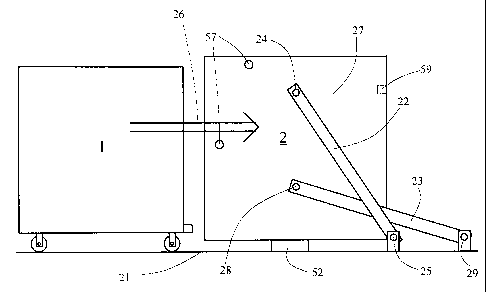
FIG. 2 is a side plan view illustrating a BMC unloader according to a
preferred embodiment of the
invention. shown alongside the typical BMC container of FIG. 1.
FIG. 3 is a side plan view illustrating the geometric movement of the BMC
unloader of FIG. 2, as it is
actuated for unloading.
FIG. 4 is a side plan view illustratina a conveyor and related components of
the preferred embodiment of
the invention.
FIG. 5 is a perspective view of a BMC unloading bin of the BMC unloader,
illustrating how the BMC
unloading bin is designed to accommodate the BMC container that it is used to
unload.
DETAILED DESCRIPTION OF THE INVENTION
Fig. 1 illustrates a typical bulk mail container (BMC) 1, such as is commoniy
used throughout the U.S.
Post Office system and by other entities such as large businesses, libraries,
etc. that receive large quantities of mail
in BMCs. BMC 1 tYpicallv comprises a plurality of BMC wheels 11 such as the
four wheels illustrated. Two of
these four wheels are typically attached so as to swivel about the illustrated
center lines 12. which facilitates the
steering of BMC 1 as it is rolled using BMC wheels 11. BMC 1 is typically
enclosed along its bottom as well as
along its four walls, and comprises a loading and unloading opening 13 along
its top, through which it is loaded and
unloaded. Of course. when BMC I contains a particularlN, large and heavy load,
itenis within BMC I must either be
unloaded bv hand, or must be dumped out of BMC 1 bv suitably upending BMC 1 so
that opening 13 becomes
oriented in a generallv downward direction. Often, the materials within BMC I
will weigh hundreds of pounds, if
not more. The front of BMC 1 typicallv also has a 2-inch lip 14 at the base of
its bodv. which is often used as a
form of "bumper."
A crossed 4-bar linkage design is employed as described below, to facilitate
the upending and controlled
unloading of BMC 1. The motivating principles behind this design concern
niinimizing actuation, and causing
rotational movement about the center of mass simultaneouslv with vertical
translation of the center of mass toward
an unloading surface such as a convevor belt. Practically, achieving a design
with optimized conditions for all three
of these constraints is challenging, due to several difficult-to-quantify
properties of the linkage in motion. These
quantities include the path of motion of the center of mass. clearance of the
BMC wheel with respect to the ground,
the dumping height, and the dumping angle.
FIG. 2 illustrates a BMC unloader 2 according to a preferred embodiment of the
invention. shown
CA 02401176 2002-08-22
WO 01/46050 PCTIUSOO/34709
3
substantially to scale alongside BMC 1. BMC 1 and BMC unloader 2 are shown
resting on the ground 21 below.
A pair of crossed bars, comprising upper bar 22 and lower bar 23 are pivotallv
attached to a BMC unloading bin 27
of BMC unloader 2 at respective upper 24 and lower 28 unloader linkage pivot
points, and are pivotallv attached
proximate ground 21 at respective inner 25 and outer 29 ground linkage pivot
points, all as illustrated. Unloader
and ground linkage pivot points 24, 28, 25 and 29 are fixed attachments
pernutting no linear movement, but only a
pivotal rotation about pivot points 24. 28. 25 and 29. The side plan view of
FIG. 2 shows onlv one side of BMC
unloader 2. A substantially identical pair of crossed bars is located on the
far (hidden) side of BMC unloader 2.
BMC unloader 2 thus comprises a total of four bars 22. 23. (two bars 22 and
two bars 23) and eight linkage pivot
points 24. 28. 25 and 29 (two pivots each of 24, 28. 25 and 29), as well as
BMC unloading bin 27. Also illustrated,
which will be discussed further in connection with FIGS. 4 and 5, are
restraining bar receptacles 57 and a bumper
lip compensator 59.
In use, as will be described in much further detail below, BMC 1 is moved
(rolled) into BMC unloader 2
along the direction indicated by arrow 26, and the combination of BMC 1 and
BMC.unloader 2 is then actuated so
as to be simultaneously linearly displaced and rotationally upended.
1 5 Fig. 3 illustrates the geometric movement of BMC unloading bin 27 as it is
actuated for unloading. The
broken lines show BMC unloader 2 in its upright position of Fig. 2: the solid
lines show BMC unloader 2 in its
upended, unloading position. The illustrated linkage moves BMC unloading bin
27 about a predetermined "center'
point 31 of BMC unloading bin 27, preferably though not limited to the center
of geometn'. Since BMCs are
loaded with a variety of combinations of materials, it is impossible to
generalize the location of the center of mass
of a fullv or partiallv loaded BMC, especially since material shifts during
the emptying process. The center of
geometrv is an adequate compromise, allowing the linkage to act on everv BMC 1
in the same manner. The path of
this center point 31 is not precisely linear and horizontal, but is a very
mild arc that very closely approximates
linearity over a significant range of the motion. As can be seen. unloader
linkage pivot points 24 and 28 will each
rotate through linkage point paths 32 illustrated by the circular ares, while
the overall loader bin moves generally
toward the right of FIG. 3 at the same time that it is rotated by about 120
degrees. such that the dumping angle 33 is
approximately 30 degrees. Unnumbered arrows -- which are schematic and do not
illustrate actual geometric paths
-- show the correspondence of two of the corners of BMC unloading bin 27
throughout this range of movement.
Generally. "center" point 31 is the point about which BMC unloading bin 27
rotates as it is also translated for
unloading: in a preferred embodiment, it coincides with the center of
geometry.
Also illustrated is an actuator 34 attached at a first end to a fixed actuator
frame 35 with the freedom to
pivot 37 about actuator pivot point 36. At its second end. it is pivotally
attached to and at center point 31 of BMC
unloading bin 27. Emploving an actuator 34 for a svstem in which the center of
geometry moves along a perfectl-,straight, horizontal path, would allow for
the actuator to be rigidly attached at is first end, i.e.. without the need to
pivot 37. However, because center point 31 moves along a very mild arc path
(almost, but not quite a straight line),
both ends of actuator 34 must be free to pivot. Actuator 34 extends from
actuator frame 35 so as to push BMC
unloading bin 27 along the path illustrated by FIG. 3. Thus, when BMC
unloading bin 27 is upright (broken line
illustration), actuator 34 (broken line also) is fully retracted. while when
BMC unloading bin 27 is in its unloading
position (solid line illustration), actuator 34 (solid line also) becomes
fullv extended. The side plan view of FIG. 3
again shows only one side of BMC unloading bin 27. A second actuator 34 is
similarly attached between a second
4 0 actuator frame 35 and a second center point 31 on the opposite, hidden
side of BMC unloading bin 27. At full
CA 02401176 2002-08-22
WO 01/46050 PCTIUSOO/34709
4
extension, actuators 3=1 must extend at least 5.5 feet, given dimensions of
tvpical BMCS, and the other dimensional
parameters discussed below.
In the preferred embodiment. the two actuators 34 each comprise a lead screw
rotated 38 bv actuator
rotation means 39 such as any standard motor. These motors or equivalents are
attached to actuator frames 35 such
that they are enable to pivot about actuator pivot points 36. The two center
points 31 (one on each side) of BMC
unloader 2 each comprise a nut pivotally attached thereto, or equivalent
means, through which the lead screws pass.
It is easy to see that as the lead screws are rotated 38 at their first
"driving" ends by actuator rotation means 39, the
rotation 38 of the second "contact ends" of these lead screws through the nuts
or equivalents of center points 31 will
push or pull the entire BMC unloader 2 in a substantially lateral direction,
either awav from or toward its upright
-0 position. These "contact ends" are to be understood as defining the points
at which actuators 34 come into contact
with and push or pull the two center points 31. and not necessarilv the
physical "ends" of the actuator. This is
emphasized bv observing that the broken line portion of Fig. 4 illustrates the
lead screw actuator embodiment
protruding well beyond (to the right of) center points 31. since the nature of
this particular embodiment is that the
lead screws actually passes through the nuts as they push BMC unloader 2
toward its upended. unloading position.
= Other equivalents or substitutes for this embodiment of actuators 34, sucli
as. but not limited to telescoping
hydraulic systems known in the art, and any other system to provide a "push"
(i.e., to linearlv extend) along a
substantially straight line, may also be apparent to someone or ordinary
skill, and are considered to be within the
scope of this disclosure and its associated claims. For some of these, the
push / pull "contact end" mav also
coincide the "physical" end.
20 Thus. when actuators 34 are actuated to move BMC unloading bin 27 from the
upright position shown
toward the left side of FIG.3 to the upended position shown toward the right
side of FIG. 3. and when BMC
container 1 has been moved 26 (see Fig. 2) into BMC unloader 2 as will be
further described below in reference to
FIG. 5. the net result is that BMC container 1 is translated substantially
linearly (to the right as illustrated by FIG.
3). and is also rotated through approximatelv 120 degrees to allow dumping of
its contents at dumping angle 33 of
2 5 approximatelv 30 degrees. As will be discussed below. dumping angle 33 can
be varied somewhat within the scope
of this disclosure and its associated claims.
As described above, BMC unloader 2 comprises two identical linkages mounted on
either side of BMC
unloading bin 27. In the preferred embodiment, BMC unloader 2 is designed to
the following specifications, which
were selected based on the size and weight characteristics of a typical bulk
mail container (BMC) 1 such as was
30 illustrated in FIG. 1. These specifications are for illustration only, and
are not limiting. It is to be understood that
someone of ordinary skill might change these specifications and still fall
within the scope of what is anticipated or
rendered obvious by this disclosure, and within the scope of the associated
claims. It is also to be observed that the
overall motion path is determined by the relative proportions of the following
dimensional parameters: 1) the
separation between ground linkage pivot points 25. 29, 2) the lengths of upper
bar 22 and lower bar 23, and 3) the
35 separation between upper 24 and lower 28 unloader linkage pivot points.
The ground linkage pivot points 25 and 29 are optimally separated bv
approximately 22.5 inches. This can
be varied by '/z inch with minimal effect. but up to 1 inch is acceptable.
so long as it is understood that changes
in this separation affect the initial BMC unloader 2 height, as well as its
final position.
Upper bar 22 and lower bar 23, optimally, are of substantially identical
length, with a distance of
40 approximatelv 61.75 inches between the pivot points at either end of these
bars. Here too, this can be varied by '/2
WO 01/46050 CA 02401176 2002-08-22 PCT/US00/34709
inch with minimal effect, and up to 1 inch is acceptable. Variations in
these bar lengths affect a number of
variables including dumping angle 33, the initial height and final position of
BMC unloader 2, the initial clearance
for BMC wheels 11, and the maximum (ceiling) height reached by BMC unloader 2
during it motion from an
upright to an unloading position.
When BMC unloader 2 is in its upright position (broken line drawing), the
lower unloader linkage pivot
points 28 are located approximateh, (x, y) =(-35.5, 20) inches from the lower
right corner of BMC unloading bin 27
as viewed in FIGS. 2 and 3. Similarly, the upper unloader linkage pivot points
24 are located approximately (x, y)
= (-35.5. 50) inches from the lower right corner of BMC unloading bin 27 as
viewed in FIGS. 2 and 3. Thus, the
separation between upper 24 and lower 28 unloader linkage pivot points is
approximately 30 inches. with the upper
unloader linkage pivot approximatelv 15 inches above, and the lower unloader
linkage pivot approximately 15
inches belo , the approximate center of geometrv of BMC unloading bin 27. In
other words, the midpoint of the
separation between tipper 24 and lower 28 unloader linkage pivot points
coincides approximately with the center of
geometry of BMC unloading bin 27. This separation can also be varied by '/2
inch ivith minimal effect. and up to
1 inch is acceptable. Variations in this separation affect the initial lieight
of BMC unloader 2.
FIG. 4 provides further illustration of the unloading process. Once BMC 1 has
been moved (26) into BMC
unloader 2 (see FIG. 2 and discussion to follow in connection with FIG. 5),
and the combination thereof has been
rotated through approximately 120 degrees as earlier described in connection
with FIG. 3, the overall system
achieves the configuration illustrated in the side plan view of FIG. 4. A
portion of BMC unloading bin 27 comes to
rest on a lower mechanical stop 41, which is also oriented at approximately 30
degrees so as to make contact with
2 o and overlap a region of the outer surface of BMC unloading bin 27,
substantially as shown. Lower mechanical stop
41 thus confines dumping angle 33 to approximately 30 degrees or less, and
prevents the BMC unloader 2 from
inverting too far. Another portion of BMC unloading bin 27 comes to rest on an
upper mechanical stop at 42,
which restrains the upper portion of this upended configuration from moving
too far into the upside down position,
also substantially as illustrated. Upper mechanical stop 42 also confines
dumping angle 33 to approximatelv 30
25 degrees or less, and prevents BMC unloader 2 from inverting too far.
An unloading surface 43 such as a table. or in a preferred embodiment, a
conveyor belt or similar
equivalent convevance means shown in FIG. 4 from an end view (i.e., with
convevance into and out of the drawing
page). resides proximate the base of lower mechanical stop 41 to receive and
transport the material contents of
BMC 1 as they are being dumped out of BMC 1. An optional unloading restraining
wall 44 ensures that materials
30 dumped out of BMC 1, across lower mechanical stop 41. and onto unloading
surface 43, do not overflow onto and
fall off of unloading surface 43. Human operators can also manually slide the
contents of BMC 1 over lower
mechanical stop 41 and onto unloading surface 43, so as to control the rate at
which materials flow out of BMC 1
and onto unloading surface 43, and. if unloading surface 43 is a convevor
belt, can do so in relation to the rate at
wllich this conveyor belt is moving. This enables a steadv. controlled flow of
the material contents out of BMC 1.
35 For reference. the above shall be referred to generally as an "unloading
station" comprising at least unloading
surface 43, and also, preferably lower mechanical stop 41, upper mechanical
stop at 42, and unloading restraining
wall 44.
The benefits of the simultaneous translation and rotation of BMC unloader 2
earlier described in
connection with FIG. 3 should now be clear. The translational movement brings
BMC 1 over toward unloading
40 surface 43 at the same time that the rotational movement suitably upends
BMC 1 so that its contents can be dumped
CA 02401176 2002-08-22
WO 01/46050 PCT/USOO/34709
6
out onto unloading surface 43. This is a unitan, motion combination, with but
a single degree of freedom, which
greatly simplifies actuation as well as the overall dumping process.
It is also to be observed how bumper lip compensator 59 compensates for BMC
lip 14 so as to ensure that
BMC I is squarely centered within BMC unloader 2 and BMC unloading bin 27.
Obviouslv. a wide range of such
bumper lip compensators can be conceived of by someone of ordinary skill
within the scope of this disclosure and
its associated claims.
At this point, while the overall dumping and unloading system, apparatus and
method of has been
described for a preferred embodiment of the invention, it is important to
describe in further detail, preciselv how
BMC unloader 2, particularh, BMC unloading bin 27, is configured so as to
accommodate BMC 1, i.e.. how BMC 1
l0 can be moved 26 into BMC unloader 2, and then suitably restrained during
upending, for unloading as lieretofore
described. This is illustrated in FIG. 5.
The geometn' of BMC unloading bin 27 is formulated to acconunodate several
notable features of a
standard BMC 1, as follows:
First. BMC unloading bin 27 is closed on three of its four sides. The fourth
side is open, comprising a
i5 BMC entnivay 58 for passage of BMC 1 into BMC unloading bin 27 as shown by
arrow 26 in Fig. 2.
As discussed in connection with FIG. I. a standard BMC 1 has four BMC wheels
11. The two fixed (non-
pivoting) wheels 11, shown toward the right side of FIG. 1. are typically 34
inches apart. The two pivoting 12
wheels 11. shown toward the left side of FIG. 1, are typically 24 inches
apart. Consequently, BMC unloading bin
27 comprises a pair of BMC wheel slots 50 in its base to accommodate these
wheels, ranging from an outer wheel
20 distance 52 of at least 34 inches to an inner wheel distance 53 of at most
24 inches. BMC 1 is loaded into BMC
unloading bin 27 fixed wheels first, to provide maximum control over
maneuvering BMC 1 into BMC unloading
bin 27 to the individual performing this task.
To facilitate loading BMC 1 into BMC unloading bin 27. BMC unloading bin 27
sits 4 inches off the
ground. This is accomplished with either the addition of legs 51 to BMC
unloading bin 27. or of a stationary block
25 52 (see FIG. 2) on which BMC unloading bin 27 rests ,hen not active.
For simplicit-Y, bumper lip compensator 59, which NN as already discussed in
FIG. 4, has been omitted from
Fig. 5.
Three devices secure BMC 1 to BMC unloading bin 27 during unloading: a
restraining ledge 54, an upper
restraining bar 55, and a side restraining bar 56. Restraining bars 55 and 56
slide into and engage restraining bar
3 0 receptacles 57 as shown by the associated arrows. Restraining ledge 54, in
conjunction with upper restraining bar
55, prevents BMC 1 froni sliding out the top of BMC unloading bin 27 when BMC
1 is upended. While illustrated
on all three edges of the top opening of BMC unloading bin 27, restraining
ledge 54 may also be varied so as to run
only along all or part of the edge farthest from BMC entnNvav 58, since this
is the region that needs to support the
most weight once BMC 1 is upended. Side restraining bar 56 holds BMC 1 into
BMC unloading bin 27 and
35 prevents possible motion out the BMC entryway 58 of BMC unloading bin 27.
Side restraining bar 56 is secured
after the operator has moved BMC 1 into BMC unloading bin 27. Upper
restraining bar 55 is either secured in this
manner, or is a permanent part of the structure of BMC unloading bin 27.
Creating additional positions for
additional bars is an option within the scope of this disclosure and its
associated claims, which allows BMC
unloading bin 27 to accommodate other tvpes of bins. And of course, other
equivalent substitute or complementary
4 0 BMC securing and restraining means for securing and restraining BMC 1
within BMC unloading bin 27 while
CA 02401176 2002-08-22
WO 01/46050 PCTIUSOO/34709
7
BMC unloading bin 27 is rotated through more than 90 degrees that would be
apparent to someone or ordinarv skill
are also encompassed within this disclosure and its associated claims.
With the particular specifications provided above (which mav, of course, be
varied bv someone of ordinarv
skill within the scope of this disclosure and its associated claims), the
masimum height of the machine during anN=
stage of the upending operation is 9ft, so that this operation can be
performed in most enclosed indoor spaces.
Optional proximity sensors (not shown) may be employed as an emergency safety
feature to detect
presence of person in this area. If interrupted, these trigger an emergency
stop to cease any further motion of the
machine.
Isolation of moving parts should be employed wherever possible.
Actuation takes place at the approximate geometric center points 31 of the
side of BMC unloading bin 27.
as noted earlier, and as shown in FIGS. 3 and 4. This is desirable for several
reasons. First. Because BMC unloader
2 rotates about the center of geometry (which is chosen to coincide as closely
as possible to the center of mass,
given the variations in load and load distribution discussed earlier),
actuation at thispoint requires less vertical
lifting in favor of horizontal pushing of BMC unloader BMC 1 and its load.
Also. the entire unloading process is
controlled bv pushing at these points, and various moments about center points
31, are minimal, and at least offset
one another.
As noted above. dumping angle 33 is optimally about 30 degrees. It can,
however, be varied by 1.5
degrees, and even as much as 3 degrees, by the possible adjustments noted
above of the relative proportions of the
separation between ground linkage pivot points 25 and 29, the lengths of upper
bar 22 and lower bar 23, and the
separation between upper 24 and lower 28 unloader linkage pivot points.
However, experimental testing to
determine the optimal angle necessarv to completelv empty BMC 1 of its
contents indicates that a dumping angle
33 of 30 degrees causes most material contents to leave the BMC, without the
dumping operation getting out of
control (i.e., dumping that is too rapid). However, since some items mav
occasionallv become caught in the
latticework at the top of a typical BMC 1, the user of this svstem. apparatus
and method mav have to run BMC 1
through its upending process a second time to empty any remaining material
contents so-caught. Testing also
reveals that dumping angle 33 should not be less than about 25 degrees. Also,
the user may not wish to completelN
empty BMC 1 for product flow reasons. Using the configuration of FIG. 4
including unloading surface 43, it
becomes possible to capture material leaving BMC 1 at a variety of positions
before the final dumping position is
achieved.
The advantage of the crossed four bar linkage comprising upper bar 22 and
lower bar 23, described
particularly in reference to FIG. 3, is that the unloading motion is confined
to one degree of freedom. Therefore,
only one actuator 34 is required to move BMC unloader 2, and consequently BMC
1, through the unloading
motions. In actuality, since two linkages (i.e., two upper 22 and lower 23 bar
pairs) are required for svnunetrv (one
pair for each side of BMC 1), two actuators 34 are required.
The unloading motion, by the nature of the four bar linkage, is itself smooth,
and warrants easv operator
control for a gradual. but single step, unloading process. The crossed four
bar causes a substantially straight-line
motion to occur for center point 31 of BMC unloading bin 27, by the very
nature of the mechanism. But
additionally, the rotation about center point 31 that accompanies this
substantially straight line motion is
advantageous for the unloading process, because BMC 1, suitably moved 26 into
BMC unloader 2, follows this
motion.
CA 02401176 2002-08-22
WO 01/46050 PCT/US00/34709
8
In an alternative embodiment. BMC unloader 2 is designed so that BMC 1 is
rotated about a point at its
front, vvith the unloading motion of the BMC entirely rotational about this
point. In other words, upper bar 22 and
lower bar 23 may be pivotally attached to a BMC unloading bin 27 so as to
create a predetermined "center" point 31
at a location other than the approximate geometric center. This can then be
applied to other applications for
unloading smaller open topped containers and bins.
In the preferred embodiment heretofore described, the length of the overall
equipment footprint, running
from the left hand side of BMC unloading bin 27 when it is upright as in FIG.
2, to the right hand side of FIG. 4, is
appro',samately 12 feet. The footprint width (the hidden depth in FIGS. 2, 3
and 4) is approximately 8 feet. With a 9
foot ceiling clearance required, the overall operational space is this 12 feet
long x 8 feet wide x 9 feet high, which is
a substantial improvement over the prior art. In particular, prior art devices
such the aforementioned Lockheed-
Martin/USPS SPBS Feed System Unloader require a"warehouse" type ceiling with a
height substantially in excess
of 9 feet.
This device and method heretofore disclosed is commercially valuable because
it accomplishes the task of
several people in far less time, in a smaller operational space, at less cost,
and with greater reliability than other
current devices that accomplish the same task.
It is also to be observed as noted earlier that the overall motion path is
determined bv the relative
proportions of the following parameters: 1) the approximately 25 inch
separation between ground linkage pivot
points 25 and 29, 2) the approximately 61.75 inch lengths of upper bar 22 and
lower bar 23, and 3) the
approximately 30 inch separation between upper 24 and lower 28 unloader
linkage pivot points. Thus, for
unloading applications other than BMC unloading, on a size scale other that of
BMCs, one would simply scale these
parameters up or down in proportion to one another to achieve the same overall
combination of translational and
rotational (upending) motion. In this context, bulk mail container (BMC) 1
generalizes to a container, the bulk mail
container (BMC) unloader system heretofore described generalizes to a
container unloader, BMC unloader 2
generalizes to a container unloader, and BMC unloading bin 27 generalizes to
an unloading bin.
Finallv, it is also intportant to emphasize that this particular choice of
proportions in this particular
combination, ivhich was uncovered by applicants following extensive modeling
and experintentation, as opposed to
other possible choices of proportions in other possible combinations, is what
is responsible for generating the
unique simultaneous translational and rotational motion of BMC unloading bin
27 that enables and underlies the
BMC unloading disclosed herein, and is what distinguishes applicants' crossed
four bar linkage in a novel and
nonobvious or inventive way from other crossed foatr bar linkages that may be
known in the art.
Of course, further points of patentable distinction over the prior art are
provided, for example, not
limitation, by: the method of using of crossed four bar linkages of these or
any other proportions specifically for
unloading applications generally and for BMC unloading applications
specifically; the use of an unloading station
such as described earlier in combination with crossed four bar linkages of
these or any other proportions; the
particular BMC unloading bin 27 configuration disclosed above (or equivalents)
that enables BMC unloading bin
27 to engage and invert a BMC 1 in connection with crossed four bar linkages
of these or any other proportions; and
the actuation of this system through greater than ninety degrees using a
substantially linearly extending actuator,
both generally and specifically as described above.
While onlvi certain preferred features of the invention have been illustrated
and described, manv
modifications and changes will occur to those skilled in the art. It is,
therefore, to be understood that the appended
CA 02401176 2002-08-22
WO 01/46050 PCT/US00/34709
9
claims are intended to cover all such modifications and changes as fall within
the true spirit of the invention.