Sélection de la langue

Search

Sommaire du brevet 2406809 

Énoncé de désistement de responsabilité concernant l'information provenant de tiers

Une partie des informations de ce site Web a été fournie par des sources externes. Le gouvernement du Canada n'assume aucune responsabilité concernant la précision, l'actualité ou la fiabilité des informations fournies par les sources externes. Les utilisateurs qui désirent employer cette information devraient consulter directement la source des informations. Le contenu fourni par les sources externes n'est pas assujetti aux exigences sur les langues officielles, la protection des renseignements personnels et l'accessibilité.

Disponibilité de l'Abrégé et des Revendications

L'apparition de différences dans le texte et l'image des Revendications et de l'Abrégé dépend du moment auquel le document est publié. Les textes des Revendications et de l'Abrégé sont affichés :

  • lorsque la demande peut être examinée par le public;
  • lorsque le brevet est émis (délivrance).
(12) Demande de brevet: (11) CA 2406809
(54) Titre français: LEVE-PATIENT MONTE SUR RAIL
(54) Titre anglais: A RAIL MOUNTED PATIENT LIFT
Statut: Réputée abandonnée et au-delà du délai pour le rétablissement - en attente de la réponse à l’avis de communication rejetée
Données bibliographiques
(51) Classification internationale des brevets (CIB):
  • A61G 07/10 (2006.01)
  • B66C 07/12 (2006.01)
(72) Inventeurs :
  • BERGERON, JEAN (Canada)
(73) Titulaires :
  • ARJO.MED.AKTIEBOLAG LIMITED
(71) Demandeurs :
  • ARJO.MED.AKTIEBOLAG LIMITED (Royaume-Uni)
(74) Agent: MARKS & CLERK
(74) Co-agent:
(45) Délivré:
(22) Date de dépôt: 2002-10-07
(41) Mise à la disponibilité du public: 2003-04-09
Licence disponible: S.O.
Cédé au domaine public: S.O.
(25) Langue des documents déposés: Anglais

Traité de coopération en matière de brevets (PCT): Non

(30) Données de priorité de la demande:
Numéro de la demande Pays / territoire Date
0124199.1 (Royaume-Uni) 2001-10-09

Abrégés

Abrégé anglais


A rail mounted patient lift comprises a ceiling mountable rail, a carriage
mounted for displacement along the rail, a flexible elongate support element
and
power operated lifting means for extending and retracting the support element
relative
to the carriage. The rail comprises a plurality of rail sections which in use
are
suspended from a ceiling with a gap therebetween at a position where the rail
is to
cross the path of a curtain. Each rail section has at least one pivotable flap
engageable by the carriage as it moves along the rail. The flap of one of a
pair of
adjoining rail sections is pivotable by the carriage as it moves in one
direction to
bridge the gap between the two sections and the flap of the other of the pair
of
adjoining rail sections is pivotable by the carriage as it moves in an
opposite direction
to bridge the gap between the two rail sections.

Revendications

Note : Les revendications sont présentées dans la langue officielle dans laquelle elles ont été soumises.


7
What is claimed is:
1.~A rail mounted patient lift comprises a ceiling mountable rail, a carriage
mounted for displacement along the rail, a flexible elongate support element
and
power operated lifting means for extending and retracting the support element
relative
to the carriage, wherein the rail comprises a plurality of rail sections which
in use are
suspended from a ceiling with a gap therebetween at a position where the rail
is to
cross the path of a curtain and wherein each rail section has at least one
pivotable flap
engageable by the carriage as it moves along the rail, the flap of one of a
pair of
adjoining rail sections being pivotable by the carriage as it moves in one
direction to
bridge the gap between the two sections and the flap of the other of the pair
of
adjoining rail sections being pivotable by the carriage as it moves in an
opposite
direction to bridge the gap between the two rail sections.
2. A rail mounted patient lift as claimed claim 1, wherein the flaps are urged
to
generally in use upstanding positions by spring means.
3. A rail mounted patient lift as claimed in claim 1, wherein each rail
section has
two parallel track portions for guiding the carriage and wherein each of the
two track
portions of each rail section has a pivotable flap.
4. A rail mounted patient lift as claimed in claim 1, further comprising power

8
operated drive means on or within the carriage for displacing the carriage
along the
rail.
5. A rail mounted patient lift as claimed in claim 1, further comprising a
sling
hanger attached to the free end of the flexible elongate support element.

Description

Note : Les descriptions sont présentées dans la langue officielle dans laquelle elles ont été soumises.

CA 02406809 2002-10-07
A RAIL MOUNTED PATIENT LTFT
INTRODUCTION
7
This invention relates to a rail mounted patient lift.
Rail mounted patient lifts are well known. One such lift is disclosed in EP-A-
1090620. The known lifts comprise a ceiling mounted rail and a carriage
mounted
for displacement along the rail usually by power operated drive means on or
within
the carriage. The lifts also comprise a flexible elongate support element,
usually
having a sling hanger attached to its free end, and power operated lifting
means for
extending and retracting the support element relative to the carriage.
These patient lifts are regularly installed in hospital wards and the like.
Curtains are also installed in hospital wards to give privacy to patients on
the ward.
There is a problem in providing cross overs between the path of the curtain
and the
I S path of a ceiling mounted patient lift.
SUMMARY OF THE INVENTION
According to the present invention there is provided a rail mounted patient
lift
comprising a ceiling mountable rail, a carriage mounted for displacement along
the
rail, a flexible elongate support element and power operated lifting means for
extending and retracting the support element relative to the carriage, wherein
the rail
comprises a plurality of rail sections which in use are suspended from a
ceiling with

CA 02406809 2002-10-07
3
a gap therebetween at a position where the rail is to cross the path of a
curtain and
wherein each rail section has at least one pivotable flap engageable by the
carriage as
it moves along the rail, the trap of one of a pair of adjoining rail sections
being
pivotable by the carriage as it moves in one direction to bridge the gap
between the
S two sections and the flap of the other of the pair of adjoining rail
sections being
pivotable by the carriage as it moves in an opposite direction to bridge the
gap
between the two rail sections.
Preferred andlor optional features of the invention are set out in claims 2 to
S, inclusive.
The invention will now be more particularly described, by way of example,
with reference to the accompanying drawings.
1S BRIEF DESCRIPTION OF THE DRAWINGS
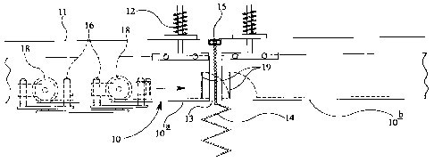
Figure 1 is a schematic side view of one embodiment of rail mounted patient
Lift in a first condition of operation,
Figure 2 is a schematic side view similar to Figure 1, but showing the rail
mounted patient lift in a second condition of operation, and
Figure 3 is a schematic side view similar to Figures I and 2 but showing the

CA 02406809 2002-10-07
rail mounted patient lift in a third condition of operation.
DESCRIPTION OF THE PREFERRED EMBODIMENTS
Referring to the drawings, there is shown a rail mounted patient lift
comprising a rail 10 attached to a ceiling 11 by suspension connecting devices
12.
The rail comprises a plurality of sections, only two of which are shown at 10a
and 10b. The rail sections are aligned longitudinally but have a small gap 13
between
adjacent ends. The gap 13 is provided at a position where the rail 10 crosses
the path
of a curtain 14 suspended from a curtain track 15 attached directly to the
ceiling 11.
The curtain track 15 extends perpendicularly to the longitudinal extent of the
rail 10.
The curtain 14 can thus be drawn across the path of the rail 10 when the rail
mounted
patient lift is not in use.
The rail mounted patient lift also comprises one or more carriages 16 mounted
for displacement along the rail 10 by power operated drive means on or within
the
carriage.
The rail 10 in cross section is of generally inverted U-shape with an in-
turned
flange 17 at the lower free end of each of the two vertical limbs of the rail
10. These
in-turned flanges 17 define two spaced apart parallel track portions for
guiding the
carriage 16 along the rail.

CA 02406809 2002-10-07
The power operated drive means on or within the carriage comprises two drive
wheels 18 which engage the two track portions 17, respectively, of the rail 10
and an
electric motor (not shown) for driving the drive wheels 18.
5 The carriage 16 also comprises a flexible elongate support element (not
shown) and power operated lifting means in the form of a winch within the
carriage
16 for extending and retracting the support element relative to the carriage.
A sling
hanger (not shown) is attached to the lower free end of the support element
which is
suspended between the two track portions 17 of the rail 10.
In order to allow the carriage 16 to bridge the gap 13 between the rail
sections
10a_ and i0b, each rail section has two pivotable flaps 19 adjacent to its
end. The two
flaps 19 of each rail section IOa, 10b are pivotably mounted on respective
track
portions and are urged to generally upstanding positions, as shown in Figure
l, by
springs, typically in the form of torsion springs. The flaps 19 are each
pivotable in
opposite directions according to the direction of travel of the carriage 16.
Thus, a
carriage 16 moving from rail section IOa to rail section IOb (with the curtain
undrawn) will engage the flaps 19 on the rail section IOa to pivot the flaps
so that
they bridge the gap 13 between the two rail sections 10a and lOb and the
carriage will
subsequently pivot the flaps on the rail section IOb_ so that these lie
horizontally
against their respective track portions I7 to enable the carriage 16 to pass
by. Figure
2 shows the flaps I9 of the rail section IOa_ bridging the gap 13 and the
carriage 16

CA 02406809 2002-10-07
in contact with the flaps 19 of the rail section l Ob. After the carriage 16
has passed
by, the flaps I9 will return to generally upstanding positions as shown in
Figure 3.
When the carriage 16 is travelling in an opposite direction the reverse will
apply and
the flaps 19 on the rail section lOb will bridge the gap 13.
In practice, the rail 10 will comprise more than two rail sections 10a and 1
Ob
with each rail section, apart from terminal sections, having flaps 19 adjacent
to
opposite ends of the rail section.
The embodiment described above is given by way of example only and various
modifications will be apparent to persons skilled in the art without departing
from the
scope of the invention as defined by the appended claims. For example, the
rail may
be of alternative cross-sectional shapes and may provide only a single track
portion
for guiding the carriage along the rail. Each rail will then have only one
flap at one
1 S or each end.

Dessin représentatif
Une figure unique qui représente un dessin illustrant l'invention.
États administratifs

2024-08-01 : Dans le cadre de la transition vers les Brevets de nouvelle génération (BNG), la base de données sur les brevets canadiens (BDBC) contient désormais un Historique d'événement plus détaillé, qui reproduit le Journal des événements de notre nouvelle solution interne.

Veuillez noter que les événements débutant par « Inactive : » se réfèrent à des événements qui ne sont plus utilisés dans notre nouvelle solution interne.

Pour une meilleure compréhension de l'état de la demande ou brevet qui figure sur cette page, la rubrique Mise en garde , et les descriptions de Brevet , Historique d'événement , Taxes périodiques et Historique des paiements devraient être consultées.

Historique d'événement

Description Date
Demande non rétablie avant l'échéance 2007-10-09
Le délai pour l'annulation est expiré 2007-10-09
Réputée abandonnée - omission de répondre à un avis sur les taxes pour le maintien en état 2006-10-10
Inactive : CIB de MCD 2006-03-12
Inactive : Supprimer l'abandon 2005-02-22
Inactive : Lettre officielle 2005-01-28
Lettre envoyée 2005-01-28
Inactive : Abandon. - Aucune rép. à lettre officielle 2005-01-10
Inactive : Transferts multiples 2005-01-07
Lettre envoyée 2004-01-26
Exigences de prorogation de délai pour l'accomplissement d'un acte - jugée conforme 2004-01-26
Inactive : Prorogation de délai lié aux transferts 2004-01-08
Inactive : Lettre officielle 2003-05-16
Demande publiée (accessible au public) 2003-04-09
Inactive : Page couverture publiée 2003-04-08
Inactive : Transferts multiples 2003-04-01
Inactive : CIB en 1re position 2002-12-06
Inactive : Lettre de courtoisie - Preuve 2002-11-26
Inactive : Certificat de dépôt - Sans RE (Anglais) 2002-11-21
Demande reçue - nationale ordinaire 2002-11-21

Historique d'abandonnement

Date d'abandonnement Raison Date de rétablissement
2006-10-10

Taxes périodiques

Le dernier paiement a été reçu le 2005-09-12

Avis : Si le paiement en totalité n'a pas été reçu au plus tard à la date indiquée, une taxe supplémentaire peut être imposée, soit une des taxes suivantes :

  • taxe de rétablissement ;
  • taxe pour paiement en souffrance ; ou
  • taxe additionnelle pour le renversement d'une péremption réputée.

Les taxes sur les brevets sont ajustées au 1er janvier de chaque année. Les montants ci-dessus sont les montants actuels s'ils sont reçus au plus tard le 31 décembre de l'année en cours.
Veuillez vous référer à la page web des taxes sur les brevets de l'OPIC pour voir tous les montants actuels des taxes.

Historique des taxes

Type de taxes Anniversaire Échéance Date payée
Taxe pour le dépôt - générale 2002-10-07
Prorogation de délai 2004-01-08
TM (demande, 2e anniv.) - générale 02 2004-10-07 2004-09-30
Enregistrement d'un document 2005-01-07
TM (demande, 3e anniv.) - générale 03 2005-10-07 2005-09-12
Titulaires au dossier

Les titulaires actuels et antérieures au dossier sont affichés en ordre alphabétique.

Titulaires actuels au dossier
ARJO.MED.AKTIEBOLAG LIMITED
Titulaires antérieures au dossier
JEAN BERGERON
Les propriétaires antérieurs qui ne figurent pas dans la liste des « Propriétaires au dossier » apparaîtront dans d'autres documents au dossier.
Documents

Pour visionner les fichiers sélectionnés, entrer le code reCAPTCHA :


Pour visualiser une image, cliquer sur un lien dans la colonne description du document. Pour télécharger l'image (les images), cliquer l'une ou plusieurs cases à cocher dans la première colonne et ensuite cliquer sur le bouton "Télécharger sélection en format PDF (archive Zip)" ou le bouton "Télécharger sélection (en un fichier PDF fusionné)".

Liste des documents de brevet publiés et non publiés sur la BDBC .

Si vous avez des difficultés à accéder au contenu, veuillez communiquer avec le Centre de services à la clientèle au 1-866-997-1936, ou envoyer un courriel au Centre de service à la clientèle de l'OPIC.


Description du
Document 
Date
(aaaa-mm-jj) 
Nombre de pages   Taille de l'image (Ko) 
Dessin représentatif 2002-12-11 1 9
Description 2002-10-06 5 157
Abrégé 2002-10-06 1 24
Revendications 2002-10-06 2 41
Dessins 2002-10-06 2 41
Certificat de dépôt (anglais) 2002-11-20 1 159
Demande de preuve ou de transfert manquant 2003-10-07 1 102
Rappel de taxe de maintien due 2004-06-07 1 109
Courtoisie - Certificat d'enregistrement (document(s) connexe(s)) 2005-01-27 1 105
Courtoisie - Lettre d'abandon (taxe de maintien en état) 2006-12-04 1 175
Rappel - requête d'examen 2007-06-10 1 118
Correspondance 2002-11-20 1 23
Correspondance 2003-05-15 1 12
Correspondance 2004-01-07 1 33
Correspondance 2004-01-25 1 14
Correspondance 2005-01-27 1 14