Sélection de la langue

Search

Sommaire du brevet 2412791 

Énoncé de désistement de responsabilité concernant l'information provenant de tiers

Une partie des informations de ce site Web a été fournie par des sources externes. Le gouvernement du Canada n'assume aucune responsabilité concernant la précision, l'actualité ou la fiabilité des informations fournies par les sources externes. Les utilisateurs qui désirent employer cette information devraient consulter directement la source des informations. Le contenu fourni par les sources externes n'est pas assujetti aux exigences sur les langues officielles, la protection des renseignements personnels et l'accessibilité.

Disponibilité de l'Abrégé et des Revendications

L'apparition de différences dans le texte et l'image des Revendications et de l'Abrégé dépend du moment auquel le document est publié. Les textes des Revendications et de l'Abrégé sont affichés :

  • lorsque la demande peut être examinée par le public;
  • lorsque le brevet est émis (délivrance).
(12) Demande de brevet: (11) CA 2412791
(54) Titre français: PATINS A ROUES ALIGNEES
(54) Titre anglais: INLINE ROLLERSKATE
Statut: Réputée abandonnée et au-delà du délai pour le rétablissement - en attente de la réponse à l’avis de communication rejetée
Données bibliographiques
(51) Classification internationale des brevets (CIB):
  • A63C 17/06 (2006.01)
(72) Inventeurs :
  • GREBER, ANDREAS (Allemagne)
  • WOLLENBERG, MATTHIAS (Allemagne)
(73) Titulaires :
  • ANDREAS GREBER
  • MATTHIAS WOLLENBERG
(71) Demandeurs :
  • ANDREAS GREBER (Allemagne)
  • MATTHIAS WOLLENBERG (Allemagne)
(74) Agent: SMART & BIGGAR LP
(74) Co-agent:
(45) Délivré:
(22) Date de dépôt: 2002-11-26
(41) Mise à la disponibilité du public: 2003-05-26
Licence disponible: S.O.
Cédé au domaine public: S.O.
(25) Langue des documents déposés: Anglais

Traité de coopération en matière de brevets (PCT): Non

(30) Données de priorité de la demande:
Numéro de la demande Pays / territoire Date
102 43 480.8 (Allemagne) 2002-09-19
201 19 159.8 (Allemagne) 2001-11-26
201 19 884.3 (Allemagne) 2001-12-07

Abrégés

Abrégé anglais


In an inline roller skate with a foot receiver which is formed for example by
a shoe and
with a frame with rollers which is provided on this receiver, these rollers
and their axles are
removably mounted on the frame by means of a quick-acting closure.

Revendications

Note : Les revendications sont présentées dans la langue officielle dans laquelle elles ont été soumises.


6
Claims
1. Inline roller skate with a foot receiver which is formed for example by a
shoe (2) and
with a frame (3) which is provided on this receiver and on which rollers (4)
are supported to be
able to turn freely using axles (8), characterized in that the rollers (4) and
their axles (8) are
removably mounted on the frame (3) by means of a quick-acting closure.
2. Inline roller skate as claimed in claim 1, wherein the quick-acting closure
is a quick-
acting closure clamping system.
3. Inline roller skate as claimed in claim 1 or 2, wherein the frame (3) has
two holding
rails (5) which are located parallel to one another and wherein the respective
axle (8) is held on
the holding rails (5) by means of the quick-acting closure (7, 13).
4. Inline roller skate as claimed in one of the preceding claims, wherein the
rollers (4) are
each a component of a roller unit which has at least one ball bearing (9) and
wherein the axle (8)
which is located within the inner ring of this ball bearing (9) is detachably
held on the frame (3)
by means of the quick-acting closure.
5. Inline roller skate as claimed in claim 4, wherein the roller unit has at
least two axially
offset ball bearings which are located on a support or spacer sleeve (10) and
wherein the axle
which is detachably mounted by means of the quick-acting closure extends
through the support
or spacer sleeve (10).
6. Inline roller skate as claimed in one of the preceding claims, wherein the
quick-acting
closure is made such that in the locked state of the quick-acting closure at
least one bearing (9)
of the respective roller (4) is clamped between the holding rails (5) of the
frame (3).

7
7. Inline roller skate as claimed in one of the preceding claims, wherein the
axle (8) on
one end has a preferably axially adjustable bearing surface for contact
against the outer side of
the holding rail (5) of the frame (3).
8. Inline roller skate as claimed in one of the preceding claims, wherein on
the other end
of the axle (8) there is a quick-acting clamping element or quick-acting
closing element, for
example a clamping lever (13) which has at least one eccentric surface (15).
9. Inline roller skate as claimed in one of the preceding claims,
characterized by receivers
(17) for interlocked holding of washers or washer-shaped sections (12, 16) of
the axle (8) with
the quick-acting closure locked.
10. Inline roller skate as claimed in one of the preceding claims,
characterized by
receivers (17, 18) which are open laterally for inserting and removing the
roller unit (6) radially
to the shaft (8).
11. Inline roller skate as claimed in one of the preceding claims, wherein the
quick-acting
mount has means for positive locking of the axle or shaft on the respective
holding rail (5).
12. Inline roller skate as claimed in one of the preceding claims, wherein the
receivers
( 17) are formed by recesses and/or beads (20).

Description

Note : Les descriptions sont présentées dans la langue officielle dans laquelle elles ont été soumises.

CA 02412791 2002-11-26
Inline Roller Skate
The invention relates to an inline roller skate as claimed in the preamble of
claim 1.
Inline roller skates are known in the most varied versions. The object of the
invention is
to devise an inline roller skate which allows the rollers to be changed
quickly and easily,
especially even without a tool.
An inline roller skate is made as claimed in claim 1 to achieve this object.
In one preferred embodiment the quick-acting closure clamping system is made
such that
the respective roller together with its bearing can be changed as a complete
roller unit.
Developments of the invention are the subject matter of the dependent claims.
The invention is
detailed below using the figures.
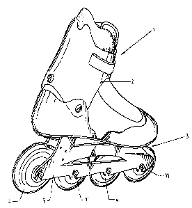
Figure 1 shows an inline roller skate in a side view;
Figure 2 shows enlarged the holding rail of the frame or chassis in the area
of a receiver
for a fully floating axle of a detachable roller unit;
Figure 3 shows a section according to line I - I of Figure 2;
Figure 4 shows a section through the two holding rails of the frame and
through a roller
unit which is attached to these holding rails by means of a quick-acting
closure;
Figure S shows in a view similar to Figure 2 a receiving opening for axles or
shafts in
another possible embodiment.
The inline roller skate which is generally labelled 1 in the figures consists
conventionally
of a one-part or mufti-part shoe 2 and of a chassis or frame 3 which is
connected to this shoe and
on which there are several rollers 4 which can turn freely. The rollers 4 in
the likewise
UE20955
21.11.2002

CA 02412791 2002-11-26
2
conventional manner are supported between the holding rails 5 of the frame 3
and are each a
component of a roller unit 6 which is detachably held on the holding rails S
as a complete
component by means of a quick-acting closure 7 in this embodiment.
As Figure 4 shows, the roller unit consists of a shaft 8 on which there are
two roller
bearings 9 for the respective roller 4 spaced axially apart from one another
by a spacer sleeve 10.
The shaft 8 on one end has an enlarged-diameter head which is formed in this
embodiment by
the head 11' of a setting screw 11 which is screwed into the threaded hole
located coaxially with
the axis of the shaft 8 on this end. Between the end of the shaft 8 and the
head 11' there is a
shim 12 with a diameter, like the diameter of the head 11, which is greater
than the cross section
of the shaft 8. On the other end, on the shaft 8 there is a lever-like quick-
acting clamping
element 13 around the axis radially to the shaft axis with the capacity to
swivel around a
threaded pin 14 which has an axis which is oriented radially to the axis of
the shaft 8. The
clamping element 13 forms two eccentric surfaces 15 which each run
eccentrically around this
axis and which are offset in the axial direction of the pin 14 against one
another. They interact
with a strain washer 16 which is located on the end of the shaft 8 there.
The eccentric surfaces 15 interact with the strain washer 16 which has a
diameter greater
than the diameter of the shaft 8 and in this embodiment equal to the diameter
of the shim 12
such that when the lever-like clamping element 13 is swivelled into the
position in which this
clamping element rests with its lever arm 13' against the strain washer 16, a
tensile or clamping
force which anchors the roller unit 6 on the frame 4 is applied to the shaft 8
via this strain
washer which is supported on the holding rail 5. This clamping force clamps
the two ball
bearings 9 with their rings which sit on the sleeve 10 and also the sleeve
itself between the inner

CA 02412791 2002-11-26
3
sides of the holding rails 5, which sides face one another. The shim 12 or the
head 11' and the
strain washer 16 are each held by interlocking in a recess 17 which is formed
on the outer side of
the pertinent holding rail 5. The recesses 17 are made such that with their
edge they surround
the respective shim 12 or washer 16 over a peripheral range of greater than
180° by interlocking.
In the area of each recess 17 the pertinent holding rail 5 has a slot 18 into
which the shaft
8 can be pushed radially to its axis when the clamping element 13 is not
tensioned such that the
respective holding rail 5 is located between the ball bearing 9 and one shim
12 or washer 16.
When the clamping element 13 is tensioned then the pertinent shim or washer is
pressed into the
recess 17 and anchored by interlocking there, with bracing of the ball
bearings and the spacer
sleeve 10 between the holding rails 5. The slots 18 are open towards the
bottom of the holding
rails 5 and extend essentially perpendicular to this bottom. The width of each
slot 18
corresponds to the outside diameter of the shaft 8. The length of each slot 18
is chosen such that
the shaft 8 which is supported against the end of the slot 18 with its axis is
coaxial to the axis of
the essentially circular recesses 17.
The screw 11 also acts as a setting screw with which the distance between the
head 11' or
the shim 12 and the clamping element 13 can be adjusted depending on the width
of the frame 3
or the distance of the outside surfaces of the holding rails 5 such that
bracing is achieved in the
optimum manner.
It was assumed above that the respective roller unit 6 can be attached to the
frame 4 as an
entire component with the quick-acting closure 13 and can be removed again
from it. But
basically according to Figure S it is also possible to provide holes 19 in the
holding rails for
supporting the shaft 8. To mount, the roller unit 6 the respective roller 4
with the ball bearings 9

CA 02412791 2002-11-26
4
and the spacer sleeve 10 which carnes these ball bearings is positioned
between the two holding
rails 5 and the shaft 8 with its end away from the clamping element without
the screw 11 there
and the shim is pushed axially through the holes 19 and the spacer sleeve 10.
Then the shim 12
and the screw 11 are mounted and then the roller unit 6 is finally fixed by
tensioning the
clamping element 13.
Other versions are also conceivable. Furthermore, other versions of the
respective
clamping element or quick-acting closure are also conceivable, for example in
the form of
clamping elements or clamping systems by means of ramps, inclined planes, but
also catch or
snap connections.
As is indicated in the figures, it is a good idea on the outside of the
holding rails 5 to
provide a bead 20 which at least partially surrounds the respective recess 17
such that this bead
reliably secures the respective shaft 8 and thus the respective roller unit 6
on the frame 3 at least
with the quick-acting closure 7 locked via the shim 12 and washer 16.
Furthermore, it is possible to make the respective roller unit 6 such that it
can only be
removed when after swivelling the clamping lever 13 into the nonlocking
position the setting
screw 11 is also loosened so that the shim 12 of the roller unit 6 can move
past the beads 20.
They represent an additional safety aspect since even if tensioning of the
clamping lever 13 has
been forgotten or the clamping lever 13 is opened because of carelessness or
under other
circumstances, the roller unit 6 cannot fall out of the frame 3.
Furthermore, instead of a screw 11 the contact surface can be implemented
differently.

CA 02412791 2002-11-26
Reference number list
1 inline roller
skate
2 shoe
3 frame
4 roller
5 holding rail
6 roller unit
7 quick-acting
closure
8 shaft
9 ball bearing
spacer sleeve
11 setting screw
12 shim
13 clamping lever
13'lever arm
14 hinge pin
eccentric surface
16 strain washer
17 recess
18 slot
19 hole

Dessin représentatif
Une figure unique qui représente un dessin illustrant l'invention.
États administratifs

2024-08-01 : Dans le cadre de la transition vers les Brevets de nouvelle génération (BNG), la base de données sur les brevets canadiens (BDBC) contient désormais un Historique d'événement plus détaillé, qui reproduit le Journal des événements de notre nouvelle solution interne.

Veuillez noter que les événements débutant par « Inactive : » se réfèrent à des événements qui ne sont plus utilisés dans notre nouvelle solution interne.

Pour une meilleure compréhension de l'état de la demande ou brevet qui figure sur cette page, la rubrique Mise en garde , et les descriptions de Brevet , Historique d'événement , Taxes périodiques et Historique des paiements devraient être consultées.

Historique d'événement

Description Date
Demande non rétablie avant l'échéance 2005-11-28
Le délai pour l'annulation est expiré 2005-11-28
Réputée abandonnée - omission de répondre à un avis sur les taxes pour le maintien en état 2004-11-26
Demande publiée (accessible au public) 2003-05-26
Inactive : Page couverture publiée 2003-05-25
Inactive : CIB en 1re position 2003-02-11
Inactive : Certificat de dépôt - Sans RE (Anglais) 2003-01-24
Demande reçue - nationale ordinaire 2003-01-20

Historique d'abandonnement

Date d'abandonnement Raison Date de rétablissement
2004-11-26

Historique des taxes

Type de taxes Anniversaire Échéance Date payée
Taxe pour le dépôt - générale 2002-11-26
Titulaires au dossier

Les titulaires actuels et antérieures au dossier sont affichés en ordre alphabétique.

Titulaires actuels au dossier
ANDREAS GREBER
MATTHIAS WOLLENBERG
Titulaires antérieures au dossier
S.O.
Les propriétaires antérieurs qui ne figurent pas dans la liste des « Propriétaires au dossier » apparaîtront dans d'autres documents au dossier.
Documents

Pour visionner les fichiers sélectionnés, entrer le code reCAPTCHA :


Pour visualiser une image, cliquer sur un lien dans la colonne description du document. Pour télécharger l'image (les images), cliquer l'une ou plusieurs cases à cocher dans la première colonne et ensuite cliquer sur le bouton "Télécharger sélection en format PDF (archive Zip)" ou le bouton "Télécharger sélection (en un fichier PDF fusionné)".

Liste des documents de brevet publiés et non publiés sur la BDBC .

Si vous avez des difficultés à accéder au contenu, veuillez communiquer avec le Centre de services à la clientèle au 1-866-997-1936, ou envoyer un courriel au Centre de service à la clientèle de l'OPIC.


Description du
Document 
Date
(aaaa-mm-jj) 
Nombre de pages   Taille de l'image (Ko) 
Description 2002-11-25 5 179
Abrégé 2002-11-25 1 9
Revendications 2002-11-25 2 72
Dessins 2002-11-25 3 56
Dessin représentatif 2003-02-18 1 12
Certificat de dépôt (anglais) 2003-01-23 1 160
Rappel de taxe de maintien due 2004-07-26 1 110
Courtoisie - Lettre d'abandon (taxe de maintien en état) 2005-01-23 1 175