Note : Les descriptions sont présentées dans la langue officielle dans laquelle elles ont été soumises.
CA 02413495 2002-12-18
A METHOD AND DEVICE FOR DETERMING AT LEAST ONE PARAMETER OF A
MIXTURE COMPRISING A CARRIER SUBSTANCE, WATER AND GAS
CROSS REFERENCE TO RELATED APPLICATIONS
This application claims the priority of German
patent application 100 30 602.0, filed June 21, 2000, the
disclosure of which is incorporated herein by reference in
its entirety.
BACKGROUND
The invention relates to a method and a device
according to the preamble of the independent claims where at
least one parameter of a mixture is to be determined, the
components of which mixture comprise a carrier substance, wa-
ter and gas.
A method of this type can in particular be used
for determining the humidity state of concrete elements. The
knowledge of the humidity state of concrete elements is often
indispensable for avoiding or assessing of damages, but also
for carrying out building and renovation steps. Furthermore,
the humidity situation has to be known when laying floors
(tiles, parquets, etc) in lofts, when coating concrete sur-
faces, and when assessing the corrosion of rebars. Hence, the
measurement of humidity is of particular importance in con-
crete construction as well.
Methods of this type can, however, also be used
in other fields, such as in the characterisation of pharma-
ceuticals and food stuff, and wherever a parameter of a mix-
ture of carrier substance, water and gas has to be deter-
mined, wherein the carrier substance can be solid or liquid.
- 1 -
CA 02413495 2002-12-18
In order to keep expense and costs small, a cor-
responding method should be non-destructive.
A method and a device for determining the humid-
ity content of porous building materials have been known from
the patent DE 196 52 679 C1. There, the humidity of the mix-
ture is determined by feeding electromagnetic waves of sev-
eral frequencies to a sensor and by determining the frequency
dependent permittivity value of the mixture by means of cali-
bration data specifically provided for the sensor. By means
of a system of equations, based on the mixing formula of Pol-
der-van Santen/de Loor, which is solved for the frequency in-
dependent parameters, the volume fraction of the liquid water
can be determined.
It has been found, however, that the accuracy of
this method is limited.
SUMMARY OF THE INVENTION
Hence, it is a general object of the invention to
provide a method and a device of the type mentioned above
that allow measurements of a higher accuracy.
In a first aspect of the invention, the permit-
tivity value of the bound water is entered into the mixing
formula as a frequency dependent function. It has been found
that a more realistic model of the system is achieved by this
step and the measurement accuracy is improved.
In a second aspect of the invention, it is as-
sumed that the contribution of the bound water does not have
to be taken into account separately. In this case, the fol-
lowing parameters (or values derived from these parameters)
are determined simultaneously from the system of equations:
- volume fraction v1 of the gas,
- 2 -
CA 02413495 2002-12-18
- volume fraction v2 of the free water,
- at least one of the depolarization factors N2~
of the free water and
- the conductivity of the free water.
With other words, these parameters are therefore
all fitted to the measured values, e.g. by calculus of obser-
vations, which provides a better modelling of the system and
therefore a higher accuracy of measurement.
Any formula describing the permittivity value of
the mixture in dependence of the permittivity value of the
components and their volume fractions can be used as mixing
formula, such as the equation of Polder-van Santen/de Loor
mentioned above. Preferably, however, a mixing formula de-
scribed in the following is used.
A third aspect of the invention relates to the
mixing formula. Preferably, a formula as follows is used
~m - ~b ~, ~, vi ' ~~.i _ ~b ~ ' ~ ~m
i -1 3 j -1 ~m + Ni j ' ~~i - ~m
with E1 and v1 being the permittivity value and the volume
fraction of the gas, e2 and v2 the permittivity value and the
volume fraction of the free water, E3 and v3 the permittivity
value and the volume fraction of the bound water (if the same
is to be taken account of), ~ the permittivity value of the
carrier substance, and N1~, N2~ and N3~ the depolarization
factors of an ellipsoidal cavity of the gas or the free water
or the bound water, respectively, wherein n = 3 when taking
the bound water into account and n = 2 when neglecting the
bound water.
If this mixing formula is measured at a suffi-
cient number for frequencies, a sufficiently determined or
overdetermined system of equations results, which allows to
determine at least one of the unknown parameters, such as the
volume fraction of the free water.
- 3 -
CA 02413495 2002-12-18
In a further aspect of the invention it is taken
into account that the water fraction of the mixture, or an-
other parameter to be determined, can vary as a function of
the depth, i.e. the distance to the surface of the mixture.
In order to take this into account, several measuring steps
are carried out, in which the sensor is arranged at a known
distance from the mixture and is separated from the same by a
dielectric of known permittivity. In each measuring step the
sensor determines a value wk depending on the integral per-
mittivity value ~ of the mixture in the measuring range.
Then, an evaluation is carried out, in which the depth de-
pendence of the liquid water fraction is determined based on
the different dependencies of the values wk from the parame-
ter to be determined.
BRIEF DESCRIPTION OF THE DRAWINGS
Further embodiments, advantages and applications
of the invention result from the dependent claims and from
the now following description with reference to the figures,
wherein:
Fig. 1 is a schematic set-up of a preferred em-
bodiment of the invention,
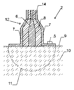
Fig. 2 is a sectional view of a surface sensor,
and
Fig. 3 is a sectional view of a hollow wave guide
sensor.
DETAILED DESCRIPTION OF THE INVENTION
The set-up of Fig. 1 comprises a permittivity
value measuring apparatus 1 for a frequency dependent deter-
mination of the complex permittivity value of a mixture. Fur-
- 4 -
CA 02413495 2002-12-18
ther, it comprises a surface sensor 2 for measuring solid
mixtures, which can be placed against a smooth and flat sur-
face, and a circular hollow waveguide sensor 3 for measuring
liquid mixtures, which can be filled into sensor 3. The sen-
sors 2 or 3 are electrically connected in selectable manner
to the permittivity value measuring device 1 via a coaxial
transmission line 14. The permittivity value measuring device
1 comprises a vector network analyzer, which measures the
real and imaginary part of the reflection factor of the used
sensor. This reflection factor is converted to a complex per-
mittivity ~ of the mixture by means of sensor specific cali-
bration data. Corresponding methods are known to the person
skilled in the art.
For evaluating the measurements, a data process-
ing system 4, such as a conventional PC, is connected to the
permittivity value measuring device 1 and controls the whole
measuring and calculation process in the manner described in
the following. A temperature sensor 5 serves to detect the
temperature of the mixture to be examined.
Fig. 2 shows a sectional view through the surface
sensor 2. It has a rotationally symmetric design with an in-
ner conductor 6 and an outer conductor 7, which are separated
by a coaxial isolation layer 8, preferably of Teflon. On its
measuring end, the temperature sensor 5 is arranged.
The surface sensor 2 can be placed against the
smooth, flat surface 9 of the mixture 10 to be measured, such
that its measuring range 11 extends into the mixture. As de-
scribed further below, it can also be arranged at a distance
from the mixture 10 to be measured such that its measuring
range 11 extends only partially into the mixture.
On a side facing the coaxial transmission line
14, the surface sensor 2 has a tapered transition section 12.
It guarantees a impedance matched connection of the surface
- 5 -
CA 02413495 2002-12-18
sensor 2 to the coaxial line 14. The transition is formed by
two cones with common tip. In such a geometry, the impedance
and the cone angles are connected via the following relation:
Z - ZFO In tan ~t92 / 2~ ( 1 )
0
2 ~ E~ tan ~t91 / 2~
Herein, ZO is the impedance of the transition
section (which is to be equal to the one of the coaxial cable
and should e.g. be 50 Ohms), ZF.O the vacuum impedance
( ZFO - ~O~EO - 3~~ Ohm) , E~ the permittivity of the isola-
tion layer 8, z91 the angle of the inner cone of the inner
conductor 6 and t92 the angle of the outer cone of the outer
conductor 7.
Fig. 3 shows a sectional view of the hollow wave
guide sensor 3. It again has a rotationally symmetric design
with an inner conductor 6 and an outer conductor 7, which are
separated by a coaxial isolation layer 8, preferably of Tef-
lon. The outer conductor 7 extends beyond the isolation layer
and the inner conductor and limits a cavity for receiving the
mixture 10 to be measured. Again, a transition section 12 for
an impedance matched connection with the coaxial transmission
line 14 can be provided.
Wit the sensors according to Figs. 2 and 3 the
permittivity is determined via the reflection of an electro-
magnetic wave. The permittivity can, however, also be meas-
ured in a transmission measurement, where e.g. the damping
and phase shift of an electromagnetic wave upon transition
through the mixture is measured. In that case the sensor con-
sists of a sender and a receiver. Corresponding techniques
are known to the person skilled in the art.
The mixture to be measured can, as already men-
tioned, be in solid or liquid form. It comprises a carrier
substance (preferably liquid or solid concrete), which forms
the predominant volume fraction of the mixture, as well as
- 6 -
CA 02413495 2002-12-18
water and gas, which are e.g. arranged in pores or cavities
in the carrier substance.
For measuring at least one parameter of this mix-
ture, we proceed as follows.
In a first step, the mixture 10 is brought into
the measuring range of the sensor 2 or 3, respectively. Then,
its temperature T is measured by means of temperature sensor
5.
Now, the complex permittivity value Em of the
mixture within the measuring range 11 is determined by means
of the permittivity value measuring device 1, namely at sev-
eral measuring frequencies fi, preferably in a range between
kHz and 10 GHz, preferably 10 MHz and 1 GHz.
These measurements are compared to a theoretical
formula based on a model of the mixture, preferably:
~m - Eb + ~, V i . ~~i _ ~~b ~ . ~, ~m
i =1 3 j =1 ~m + Ni j ' ~Ei - ~m
Here, E1 and v1 designate the permittivity value and volume
fraction of the gas, E2 and v2 the permittivity value and
volume fraction of the free water, ~3 and v3 the permittivity
value and volume fraction of the bound water, E,b the permit-
tivity value of the carrier substance and N1~, N2~ and N3~
the depolarization factors of an ellipsoidal cavity of the
gas or the free water or the bound water, respectively. If
the contributions of the bound water are taken into account,
n is equal to 3. If these contributions are neglected, n is
equal to 2.
By entering the measured value Em(fi) into equa-
tion (2) a system of equations is obtained. If a sufficient
number of measurement values is available, an evaluation of
the system of equations allows to determine different parame-
ters of the mixture, as it is described in the following.
Preferably, the number of measurements is chosen to be so
CA 02413495 2002-12-18
high that the system of equations is overdetermined and the
parameters can be determined by calculus of observations with
high accuracy.
It is to be noted that besides equation (2) other
approaches and approximations exist that estimate the permit-
tivity value ~m of a mixture. One other equation, described
in DE 196 52 679, is the mixing formula of Polder-van San-
ten/de Loor. Furthermore, various approximations can e.g. be
used for the depolarization factors. For example, by assuming
rotational symmetry for the depolarization factors of the
free water, the following approximations can be used:
N21 = N2 2 _ Nfw ( 3 )
N23 _ 1 _ 2.Nfw,
i.e. the depolarization effects in the cavities of the free
water can be expressed by a single parameter Nfw-
For the depolarization factors of gas, the fol-
lowing assumption is found to be reasonable:
N11 = N12 - N13 = 1 / 3 ( 4 )
For the depolarization factors of the bound wa-
ter, the following approximation can be used:
N31 = N32 - 0 and N33 - 1. (5)
In general, the mixing formula have, when the
contribution of bound water is taken into account, the fol-
lowing form
_ ~n,(e1, ~2, ~3, Eb, v1, v2, v3) , (6)
_ g _
CA 02413495 2002-12-18
i.e. the permittivity value of the mixture is given as a
function of the permittivity values of the components and the
volume fractions. Where applicable, further parameters can be
taken into account as unknowns in equation (6), such as at
least one depolarization factor of a component of the mix-
ture, in particular a depolarization factor of free water,
e.g. the depolarization factor Nfw of equation (3).
If the contribution of the bound water is not
taken into account or neglected (or, taken into account in
approximation as a constant contribution to the permittivity
value sb of the carrier substance), and if approximations of
the type of equations (3), (4) and (5) are used for the depo-
larization factors, it results:
em = 8m(E1, E2, Eb, v1, v2, Nfw) . (7)
Some of the parameters in equations (2), (6) or
(7) can be estimated with sufficient accuracy, while others
can only be determined by the measurement.
The permittivity value E1 of the gas at the used
frequencies can be set to 1 + O~i in good approximation.
For the permittivity value E2 of the free water
the Cole-Cole approximation can be used:
stat fw _ (8)
~2 (f ) _ ~~(f w) + 1 -I- {.i (. C~J Z f )1 a 1 . l~ f ~0 ,
w
with the parameters Estat (fw) ~ ~( fw) ~ Zfw~ a~ and Qfw,
wherein eo = 8.8642x10⁻¹² F/m and c~ = 2~f. Estat(fw) corre-
sponds to the static dielectric constant of free water,
~(fw) to the dielectric constant of free water at optical
frequencies, Zfw to the relaxation time of free water, a =
0.02 and Qfw to the conductivity of free water. Numerical,
_ g _
'- CA 02413495 2002-12-18
temperature and salt dependent values of the corresponding
parameters are published in "Permittivity Measurements Using
Open-Ended Sensors and Reference Liquid Calibration - An Un-
certainty Analysis", by A. Nyshadham et al., IEEE Transac-
tions on Microwave Theory and Techniques, Vol. 40(2), pp.
305ff, 1992.
For the permittivity value E3 of the bound water,
the Cole-Cole approximation can be used as well:
Estat(bw~ - ~~(bw~ lbw
E3 (f ) = E~(bye) '~' - 1 ' . ( 9 )
1 + (i ~ l~ ' zbw ~ a ~ ~ Eo
with the parameters Es tat (bw) ~ ~(bw) ~ Zbw~ a~ and a~br,~, and
with eo = 8.8642x10'12 F/m and to = 2~f. Preferably, the fol-
lowing values are used:
Es tat (bw) -- 80,
~(bw) -- 4.5,
abW = -7.721x10⁻¹⁴T3 + 1.017x10⁻¹¹T2 - 5.516x10⁻¹⁰T +
1.645x10⁻⁸ seconds (temperature T in °C),
oc = 0 , and
6b~, ~ 0 .
The permittivity value Eb of the carrier sub-
stance is generally known from calibration measurements.
The volume fractions v1, v23 and v3 give, when
added, the porosity of the carrier substance. If the contri-
bution of the bound water is not taken into account, v3 can
be set to zero. In many practical applications, the volume
fraction v3 is a fixed quantity, because bound water is al-
ways present in the carrier substance and is hard to remove.
For concrete, v3 has a value of approximately 0.016.
From equation (7) (or equation (2) respectively,
with v3 = 0 and the approximations (3) and (5)) a system of
equations results when at least four measuring values at dif-
ferent frequencies are evaluated and the above values for the
known parameters are used, which system of equations allows
- 10 -
CA 02413495 2002-12-18
the simultaneous determination of the following unknown pa-
rameters:
- volume fraction v1 of the gas,
- volume fraction v2 of the free water,
- at lest one of the depolarization factors N2~
of the free water, in particular Nfy,, when using the approxi-
mation (4), and
- electric conductivity of the free water.
Instead of these parameters, other values depend-
ing on these parameters can be determined. In particular, the
salt contents of the free water can e.g. be determined from
the conductivity of the free water by using empirical equa-
tions according to the above mentioned publication of A.
Nyshadham et al. Corresponding conversion formulas are known
to the person skilled in the art.
If the contribution of the bound water is not ne-
glected and taken account of explicitly, the number of the
unknown parameters increases. It is found, however, that it
is still possible to make an accurate measurement when a good
estimate for the permittivity value E3 is used. For this pur-
pose it is important that it is taken into account that this
permittivity value 83 is frequency dependent at the used
measuring frequencies, i.e. in general E3 = e3(f). For exam-
ple, equation (9) can be used as specific formula. Depending
on the frequency range, the real value of equation (9) can be
set to a constant value of e.g. 4.5. In particular, as men-
tioned before, it can be said in good approximation that, at
the given frequency, the conductivity Qby~, of the bound water
is zero.
Hence, when taking the contributions of the free
water into account, at least one parameter, in particular the
volume fraction v2 of the free water, can be determined from
- 11 -
CA 02413495 2002-12-18
equation (2) or (5) when entering the measuring values into
the system of equations.
With the method described above, it is also pos-
sible to determine the porosity of the carrier substance as a
sum of the volume fractions v1 + v2 (or v1 + v2 + v3 when
taking the bound water into account).
Furthermore, the volumetric amount of water can
be determined with the present method from the value v2 or
the sum v2 + v3. When the pure density of the carrier sub-
stance is known and the known or determined porosity is taken
into account, the weight fraction of water content can be de-
termined as follows:
Proh - Prein ' ~1 - 8)
with:
Proh gross density [e. g. g/cm3]
Prein pure density [e. g. g/cm3]
8 porosity [ - ]
and:
wool.
gew.
Proh
with:
wgeiy, weight fraction of water content [M. -~ ]
~~'vol. volume fraction of water content [vol.-~]
The pure density can be determined in simple man-
ner in a laboratory by means of standard procedures.
In the above discussion it has been assumed that
the permittivity value Em of the mixture is position inde-
pendent. If this is not the case, the measured value Em is an
average value, i.e. an integral value, of the permittivity of
the mixture within the measuring range 11 of the sensor.
- 12 -
CA 02413495 2002-12-18
In particular for solid mixtures the permittivity
value is, however, often a parametric function f of the
depth, i.e. of the distance from the surface, for example
f(x) - a1 + a2-(1-exp(-x/a3)), (9)
wherein a1, a2 and a3 are unknown parameters.
It has been found that the present method allows
the determination of the depth dependent liquid water frac-
tion, or, analogously, of another depth dependent parameter
(such as the salt content).
For this purpose, several measuring steps k are
carried out, wherein in each measuring step the sensor is ar-
ranged at a known distance from the mixture and is separated
from the same by a dielectric of known permittivity. The di-
electric can, in particular, also be air, and in one of the
measuring steps the distance is preferably 0. Between measur-
ing steps, the distance between the sensor and the mixture is
changed, or another dielectric is introduced between the sen-
sor and the mixture. In most measuring steps, the measuring
range of the sensor will therefore enter only partially and
in differently strong manner into the mixture.
In each measuring step, a value wk depending on
the integral permittivity value Emk is measured, such as e.g.
the water fraction or the salt content. For this purpose, it
can e.g. be assumed that the permittivity value 8m is con-
stant over the measuring range, such that the above evalua-
tions can be used. From the changing dependence of the values
wk from the parameter to be measured (such as the water frac-
tion) in the measuring range, the values a1, a2, a3 and
therefore the function f can be determined.
Preferably, the integral
- 13 -
CA 02413495 2002-12-18
wk - f Ek ~X~fal, a2, . . . ~x~ ( 10 )
is calculated for each measuring step k, wherein Ek(x) is a
normalized dependence of the sensitivity of the sensor from
the depth x in the mixture in the conditions of measuring
step k (distance between sensor and mixture and permittivity
of the dielectric).
The dependence Ek(x) can e.g. be determined by
previous calibration measurements under the measuring condi-
tions of the measuring step, or numerically, e.g. by finite
element calculus.
For example, it can be based on the sensitivity
S(x) of the sensor lying against the mixture. If the distance
between sensor and mixture in measuring step k is equal to dk
and the permittivity value of the dielectric between sensor
and mixture is approximately equal to the average permittiv-
ity value of the mixture, we get in approximation:
Ek(x) - S(x + dk) (11)
By entering the measuring values wk in equation
(10), it is again possible to set up a system of equations
for the parameters a1, a2, a3...., which can be solved by
means of the calculus of observations.
While, in the present application, preferred em-
bodiments of the invention are described, it is to be dis-
tinctly understood that the invention is not limited thereto
and can also be carried out in different manner within the
scope of the following claims.
- 14 -